Benning CM 9 User manual

DBedienungsanleitung
Operating manual
FNotice d‘emploi
EInstrucciones de servicio
Návod k obsluze
Οδηγίεςχρήσεως
HKezelési utasítás
IIstruzioni d’uso
Gebruiksaanwijzing
Instrukcjaobsługi
Инструкцияпоэксплуатации
индикаторанапряжения
Kullanma Talimati
BENNING CM 9

11/ 2008
BENNING CM 9
D F E H I
Bild 1: Gerätefrontseite
Fig. 1: Appliance front face
Fig. 1: Partie avant de l’appareil
Fig. 1: Parte frontal del equipo
Obr. 1: Přední strana přístroje
εικόνα 1: Το μπροστινό τμήμα της συσκευής
1. bra: A mérőkészülék elölnézete
Ill. 1: Lato anteriore pinza
Fig. 1: Voorzijde van het apparaat
Rys. 1: Panel przedni przyrządu
См. рис. 1: Вид спереди.
Resim 1: Cihaz ön yüzü.
3
4
5
9
6
K
L
N
O
7
2
P
8

11/ 2008
BENNING CM 9
D F E H I
Bild 3: Differenzstrommessung, Verbraucher 1-phasig gespeist, mit N-Leiter
Fig. 3: Leakage current measurement at single-phase systems
Fig. 3: Mesure du courant de fuite aux systèmes monophasés
Fig. 3: Medida de corriente de fugas en sistemas monofásicos
Obr. 3: Měření svodového proudu u jednofázových systémů
εικόνα 3: Μέτρηση του ρεύματος διαφυγής σε μονοφασικά συστήματα.
3. bra: Levezetési áram mérése egyfázisú rendszereken
Ill. 3: Misurazione della corrente di dispersione nei sistemi monofase
Fig. 3: Lekstroommeting in 1-fase systemen
Rys. 3: Pomiar prądu upływu w systemach jednofazowych
См. рис. 3: Измерение тока утечки в однофазной системе
Resim 3: Tek fazlı sistemlerde deşarj akımı ölçümü
Bild 2: Ableitstrommessung über Erdleiter („Ableitleiter“)
Fig. 2: Leakage current measurement at the ground conductor
Fig. 2: Mesure du courant de fuite au conducteur de mise à la terre
Fig. 2: Medida de corriente de fugas en el conductor de tierra
Obr. 2: Měření svodového proudu na zemnícím vodiči
εικόνα 2: Μέτρηση του ρεύματος διαφυγής στον αγωγό της γείωσης
2. bra: Levezetési áram mérése a földelő vezetőn
Ill. 2: Misurazione della corrente di dispersione sul conduttore di terra
Fig. 2: Lekstroommeting aan de aardgeleider
Rys. 2: Pomiar prądu upływu w przewodach uziemiających
См. рис. 2: Измерение тока утечки на заземляющем проводе
Resim 2: Toprak kablosunda deşarj akımı ölçümü
L
N
E, PE
L
N
E, PE

11/ 2008
BENNING CM 9
D F E H I
Bild 5: Differenzstrommessung, Verbraucher 3-phasig gespeist, ohne N-Leiter
Fig. 5: Leakage current measurement, load supplied in three-phase, without N-type conductor
Fig. 5: Mesure du courant de fuite, appareil connecté avec alimentation triphasée, sans conducteur type N
Fig. 5: Medida de corriente de fugas, cargas alimentadas en trifásica sin conductor neutro
Obr. 5: Svodový proud měření, spotřebič napájen 3-fázovým proudem, bez vodiče N
εικόνα 5: Μέτρηση του ρεύματος διαφυγής, Τροφοδοσία καταναλωτή με 3-φασικό ρεύμα, χωρίς ουδέτερο (Ν) αγωγό)
5. bra: Levezetési áram mérése, fogyasztó 3 fázisúan betáplálva, N-vezeték nélkül
Ill. 5: Misurazione della corrente di dispersione, utenti alimentazione trifase, senza conduttore N
Fig. 5: Lekstroommeting verbruikers 3-fase gevoed, zonder nul
Rys. 5: Pomiar prądu upływu w sieci trójfazowej bez przewodu N
См. рис. 5: Измерение тока утечки, трехфазное питание потребителя, без нейтрали
Resim 5: Deşarj akımı ölçümü, tüketici 3 faz beslemeli, N kablosuz
Bild 4: Ableitstrommessung über Erdleiter (Ableiter) bei 3-phasiger Versorgung
Fig. 4: Leakage current measurement via ground conductor (charge eliminator) for three-phase supply
Fig. 4: Mesure du courant de fuite au moyen du conducteur de mise à la terre (paratonnerre) pour alimentation triphasée
Fig. 4: Medida de corriente de escape a través de conductor de tierra (descargador) con suministro trifásico
Obr. 4: Měření svodového prudu přes zemní vodič (svodič) při napájení 3-fázovým proudem
εικόνα 4: Mέτρηση ρεύματος διαρροής μέσω αγωγών γείωσης σε τριφασική τροφοδοσία ρεύματος
4. bra: Levezetési áram mérése földelő vezetőn (túlfeszültség-levezetőn) keresztül 3 fázisú áramellátásnál
Ill. 4: Misurazione della corrente di dispersione tramite conduttore di massa (deviatore) in presenza di alimentazione trifase
Fig. 4: Lekstroommeting via aardleider (ontlader) bij 3-fasen verzorging
Rys. 4: Pomiar prądu upływowego za pośrednictwem przewodu uziemiającego (odgromnika) przy zasilaniu 3-fazowym
См. рис. 4: Измерение тока утечки через заземляющий провод (разрядник) при 3-х фазном снабжении
Resim 4: 3-fazlı beslemede toprak hattı üzerinden deşarj akımının ölçümü
L1
L2
L3
E, PE
L1
L2
L3
N
E, PE

11/ 2008
BENNING CM 9
D F E H I
Bild 7: Wechselstrommessung
Fig. 7: Alternating current measurement
Fig. 7: Mesure de courant alternatif
Fig. 7: Medición de corriente alterna
Obr. 7: Měření střídavého proudu
εικόνα 7: Μέτρηση εναλλασσόμενης έντασης
7. bra: Váltakozó áram mérés
Ill. 7: Misurazione di corrente alternata
Fig. 7: Meten van wisselstroom.
Rys. 7: Pomiar prądu przemiennego
См. рис. 7: Измерение переменного тока
Resim 7: Alternatif Akım Ölçümü
CAT.IV 800 V
with respect to
earth for the jaw.
Barrier for Hand
Guard
Do not hold the meter
above the Barrier
�
�
←
Bild 6: Differenzstrommessung, Verbraucher 3-phasig, mit N-Leiter gespeist
Fig. 6: Leakage current measurement, load supplied in three-phase, with N-type conductor
Fig. 6: Mesure du courant de fuite, appareil connecté avec alimentation triphasée, avec conducteur type N alimenté
Fig. 6: Medida de corriente de fugas, cargas alimentadas en trifásica con conductor neutro
Obr. 6: Svodový proud měření, spotřebič napájen 3-fázovým proudem, napájen s vodičem N
εικόνα 6: Μέτρηση του ρεύματος διαφυγής, Τροφοδοσία καταναλωτή με 3-φασικό ρεύμα, με ουδέτερο αγωγό)
6. bra: Levezetési áram mérése, fogyasztó 3 fázisúan betáplálva, N-vezetékkel betáplálva
Ill. 6: Misurazione della corrente di dispersione, utenti alimentazione trifase, con conduttore N
Fig. 6: Lekstroommeting verbruikers 3-fase gevoed, met nul
Rys. 6: Pomiar prądu upływu w sieci trójfazowej z przewodem N
См. рис. 6: Измерение тока утечки, трехфазное питание потребителя, с нейтралью
Resim 6: Deşarj akımı ölçümü, tüketici 3 faz beslemeli, N kablo ile beslemeli
L1
L2
L3
N
E, PE

11/ 2008
BENNING CM 9
D F E H I
Bild 8: AutoHold – Messwertspeicher
Figure 8: AutoHold – measured value memory
Figure 8: AutoHold – mémoire de valeurs mesurées
Figura 8: AutoHold – memoria de valores de medición
Obr. 8: AutoHold – paměť naměřených hodnot
Eικόνα 8: AutoHold – μνήμη μετρούμενων τιμών
8. brá: AutoHold – mérési adattároló
Ill. 4 8: AutoHold – unità di memorizzazione dei valori di misurazione
Fig. 8: AutoHold – meetwaarde-geheugen
Rys. 8: AutoHold – pamięć wartości pomiaru
Рис. 8: AutoHold – Запоминающее устройство измеренных величин
Resim 8: AutoHold – ölçüm değeri hafızası
AutoHold
Press > 5 sec.
Press < 5 sec.
Bild 9: Batteriewechsel
Fig. 9: Battery replacement
Fig. 9: Remplacement des piles
Fig. 9: Cambio de pilas
Obr. 9: Výměna baterií
εικόνα 9: Αντικατάσταση μπαταρίας
9. bra: Telepcsere
Ill. 9: Sostituzione batterie
Fig. 9: Vervanging van de batterijen
Rys. 9: Wymiana baterii
См. рис. 9: Замена батареи
Resim 9: Batarya değişimi

11/ 2008
BENNING CM 9
1
D
Bedienungsanleitung
BENNING CM 9
Digitale-Leckstromzange zur
- Messung von Ableitströmen (Differenz- und Schutzleiterstrom) in elek-
trischen Anlagen und Geräten
Inhaltsverzeichnis
1. Benutzerhinweise
2. Sicherheitshinweise
3. Lieferumfang
4. Gerätebeschreibung
5. Allgemeine Angaben
6. Umgebungsbedingungen
7. Elektrische Angaben
8. Messen mit dem BENNING CM 9
9. Instandhaltung
10. Umweltschutz
1. Benutzerhinweise
Diese Bedienungsanleitung richtet sich an
- Elektrofachkräfte und
- Elektrotechnisch unterwiesene Personen
Das BENNING CM 9 ist zur Messung in trockener Umgebung vorgesehen. Es
darf nicht in Stromkreisen mit einer höheren Nennspannung als 300 V AC einge-
setzt werden (näheres hierzu im Abschnitt 6: Umgebungsbedingungen).
In der Bedienungsanleitung und auf dem BENNING CM 9 werden folgende
Symbole verwendet:
Anlegen um GEFÄHRLICH AKTIVE Leiter oder Abnehmen von diesen
ist zugelassen.
Warnung vor elektrischer Gefahr!
Steht vor Hinweisen, die beachtet werden müssen, um Gefahren für
Menschen zu vermeiden.
Achtung Dokumentation beachten!
Das Symbol gibt an, dass die Hinweise in der Bedienungsanleitung zu
beachten sind, um Gefahren zu vermeiden.
Dieses Symbol auf dem BENNING CM 9 bedeutet, dass das
BENNING CM 9 schutzisoliert (Schutzklasse II) ausgeführt ist.
Dieses Symbol erscheint in der Anzeige für eine entladene Batterie.
(AC) Wechsel- Spannung oder Strom.
Erde (Spannung gegen Erde).

11/ 2008
BENNING CM 9
2
D
2. Sicherheitshinweise
Das Gerät ist gemäß
DIN VDE 0411 Teil 1/ EN 61010-1
gebaut und geprüft und hat das Werk in einem sicherheitstechnisch einwand-
freien Zustand verlassen.
Um diesen Zustand zu erhalten und einen gefahrlosen Betrieb sicherzustellen,
muss der Anwender die Hinweise und Warnvermerke beachten die in dieser
Anleitung enthalten sind.
Vorsicht bei Arbeiten um blanke Leiter oder Hauptleitungsträger.
Ein Kontakt mit Leitern kann einen Elektroschock verursachen.
Die BENNING CM 9 darf nur in Stromkreisen der Überspan-
nungskategorie III mit max. 300 V AC Leiter gegen Erde benutzt
werden.
Beachten Sie, dass Arbeiten an spannungsführenden Teilen und
Anlagen grundsätzlich gefährlich sind. Bereits Spannungen ab
30 V AC und 60 V DC können für den Menschen lebensgefährlich
sein.
Vor jeder Inbetriebnahme überprüfen Sie das Gerät auf
Beschädigungen.
Ist anzunehmen, dass ein gefahrloser Betrieb nicht mehr möglich ist, ist das
Gerät außer Betrieb zu setzen und gegen unbeabsichtigten Betrieb zu sichern.
Es ist anzunehmen, dass ein gefahrloser Betrieb nicht mehr möglich ist,
- wenn das Gerät sichtbare Beschädigungen aufweist,
- wenn das Gerät nicht mehr arbeitet,
- nach längerer Lagerung unter ungünstigen Verhältnissen,
- nach schweren Transportbeanspruchungen,
- wenn das Gerät feucht ist.
Wartung:
Das Gerät nicht öffnen, es enthält keine durch den Benutzer
reparablen Bauteile. Reparatur und Service kann nur durch
qualifiziertes Personal erfolgen.
3. Lieferumfang
Zum Lieferumfang des BENNING CM 9 gehören:
3.1 ein Stück BENNING CM 9,
3.2 ein Stück Kompakt-Schutztasche,
3.3 zwei Stück 1,5 V-Microbatterien/ TypAAA(IEC LR 03) zur Erstbestückung
im Gerät eingebaut,
3.4 eine Bedienungsanleitung.
Hinweis auf Verschleißteile:
- Das BENNING CM 9 benötigt zwei 1,5-V-Microbatterien/Typ AAA (IEC LR 03)
4. Gerätebeschreibung
siehe Bild 1: Gerätefrontseite
Die in Bild 1 angegebenen Anzeige- und Bedienelemente werden wie folgt be-
zeichnet:
1Messzange, zum Umfassen stromdurchossener Leiter,
2Öffnungshebel, zum Öffnen und Schließen der Stromzange,
3Digitalanzeige,
4APO, erscheint wenn Auto Power Off aktiviert ist (Gerät schaltet sich nach
20 min. aus)
5Batterieanzeige, erscheint bei entladener Batterie,
6AutoRange, erscheint wenn AutoRange aktiviert ist
7AUTO BACKLIT, Sensor der automatischen Hintergrundbeleuchtung
8Tiefpass-Filter (50-60Hz) aktiv, Tiefpasslter mit einer Grenzfrequenz von
ca.100 Hz und - 24 dB/ octave
9
Compare, Komparator aktiv (Vergleichswerte: 0,25 mA, 0,5 mA und 3,5 mA)
Hold, erscheint wenn Hold aktiviert wurde,
KAutoHold, erscheint wenn AutoHold aktiviert ist,
LPeakHold, erscheint wenn die automatische Spitzenwertspeicherung
aktiviert ist,
MRange, AutoRange deaktivieren, Messbereiche auswählen und AutoRange
aktivieren.

11/ 2008
BENNING CM 9
3
D
N
Wide/50-60Hz, Compare, Tiefpasslter aktivieren und deaktivieren,
OHOLD/PEAK , dient zum Ein- und Ausschalten der BENNING CM 9 und
der Aktivierung einzelner Hold-Funktionen,
PStromzangenwulst, schützt vor Leiterberührung
5. Allgemeine Angaben
5.1 Allgemeine Angaben zur Stromzange
5.1.1 Die Digitalanzeige 3ist als 35/6-stellige Flüssigkristallanzeige mit 12 mm
Schrifthöhe mit Dezimalpunkt ausgeführt. Der größte Anzeigewert ist
6000.
5.1.2 Die Bereichsüberschreitung wird mit „.0L“ angezeigt.
Achtung, keine Anzeige und Warnung bei Überlast
5.1.3 Das BENNING CM 9 wird durch die Taste Oein- oder ausgeschaltet,
zum Ausschalten die Taste für ca. 5 sec. gedrückt halten.
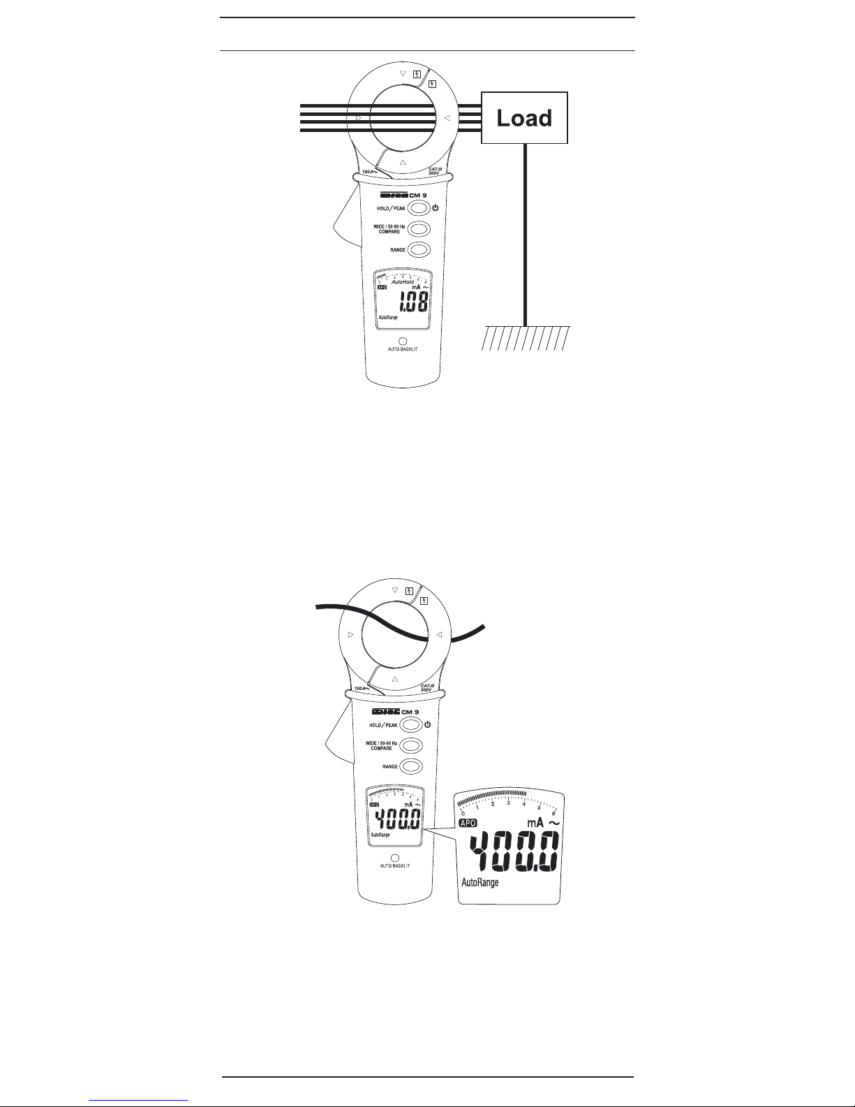
5.1.4 RANGE, die Bereichstaste „RANGE“ Mdient zur Weiterschaltung in
die einzelnen Messbereiche (6 mA, 60 mA, 600 mA, 6 A, 60 A, 100 A)
AutoRange wird durch gedrückt halten (ca. 2 sec.) der Taste „RANGE“
Maktiviert. Im Display 3wird „AutoRange“ 6eingeblendet.
5.1.5 Hold, die Hold-Funktion speichert den aktuellen Messwert, zum
Speichern die Taste „HOLD/PEAK“ Okurz drücken, sollte der Messwert
um 50 Messschritte überschritten werden beginnt das Display zu
blinken, zusätzlich ertönt ein akustisches Signal.
5.1.6 PeakHold speichert kontinuierlich den maximal ermittelten Messwert,
zur Aktivierung der kontinuierlichen Spitzenwertspeicherung die Taste
„HOLD/PEAK“ Ofür ca. 2 sec. gedrückt halten. Bei Aktivierung der
PeakHold-Funktion wechselt die BENNING CM 9 in den manuellen
Bereichsmodus
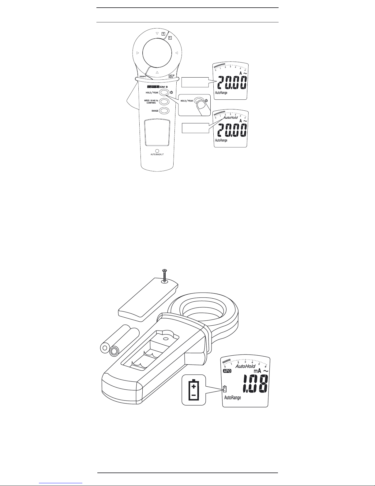
5.1.7 AutoHold ändert sich der Messwert innerhalb von 10 Messzyklen nicht,
wird dieser Messwert gespeichert und „AutoHold“ Kwird im Display
eingeblendet. Die Messung erfolgt kontinuierlich, ändert sich der
Messwert wird „AutoHold“ Kausgeblendet und ein akustisches Signal
ertönt.
Um AutoHold zu aktivieren muss die BENNING CM 9 ausgeschaltet
sein (siehe Bild 8), drücken Sie die Taste „HOLD/PEAK“ Ound halten
diese für ca. 5 sec. gedrückt, im Display blinkt 3 mal die Anzeige
„AutoHold“ Kund es ertönen 2 Signaltöne im Abstand von ca. 1 sec..
Die AutoHold-Funktion ist nun aktiviert. Um AutoHold zu deaktivieren,
schalten Sie die BENNING CM 9 aus und durch kurzes drücken der
Taste „HOLD/PEAK“ Owieder ein.
5.1.8 Die Taste „Wide/50-60Hz, Compare“ Nhat zwei Funktionen:
Der Tiefpassfilter kann nur bei manueller Messbereichswahl aktiviert
werden. Störsignale werden ab einer Grenzfrequenz von 100 Hz mit
- 24 dB/ octave gedämpft. Durch kurzes betätigen der Taste „Wide/50-
60Hz/Compare“ Nwird der Tiefpassfilter (50 Hz -100 Hz) aktiviert. Ein
aktiver Filter wird durch das Symbol „50-60 Hz“ 8visualisiert.
Durch betätigen der Taste „Wide/50-60Hz/Compare“ Nfür ca. 3 sec.
wird die Komparator-Funktion aktiviert. „Compare“ 9erscheint in der
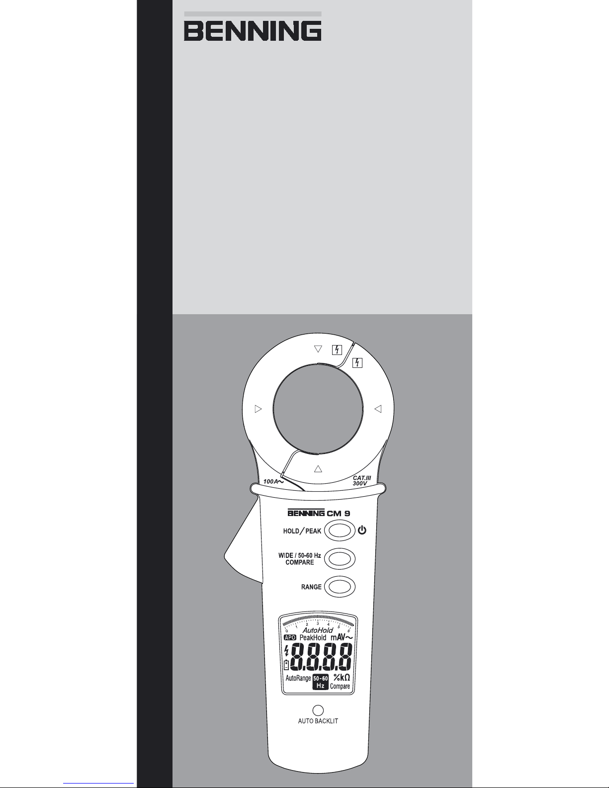
Digitalanzeige3.DieLeckstromzangeliefert3gespeicherteGrenzwerte:
0,25 mA, 0,5 mA und 3,5 mA. Die Vergleichsfunktion ermöglicht eine
direkte Überprüfung auf Überschreitung der Grenzwerte. Der interne
Summer ertönt und die Digitalanzeige 3blinkt, wenn der gemessene
Wert den Grenzwert überschreitet. Durch längeren Tastendruck > 1 sec.
der Taste „Wide/50-60Hz, Compare“ Nwird zunächst der ausgewählte
Grenzwert angezeigt (die Anzeige blinkt) durch die Taste „RANGE“ M
kann durch die Grenzwerte gerollt werden. Bestätigt wird die Auswahl
durch erneuten Tastendruck auf die Taste „Wide/50-60Hz, Compare“
N. Die Vergleichsfunktion ist nun eingestellt und aktiv.
5.1.9 Das BENNING CM 9 schaltet sich nach ca. 20 Minuten selbstständig ab
(APO, Auto-Power-Off). Es schaltet sich wieder ein, wenn die Taste O
betätigt wird. Ein Summerton signalisiert die selbsttätige Abschaltung
des Gerätes. Die automatische Abschaltung lässt sich deaktivieren
indem sie beim Einschalten die Taste O> 3 sec. gedrückt halten.
5.1.10 Die Messrate des BENNING CM 9 beträgt nominal 5 Messungen pro
Sekunde für die Digitalanzeige.
5.1.11 Hinter dem Fenster „AUTO BACKLIT“ 7befindet sich der
Helligkeitssensor. Sobald die Umgebungsbeleuchtung sinkt, schaltet
sich die Hintergrundbeleuchtung ein.
5.1.12 Temperaturkoeffizient des Messwertes: 0,2 x (angegebene
Messgenauigkeit)/ °C < 18 °C oder > 28 °C, bezogen auf den Wert bei
der Referenztemperatur von 23 °C.
5.1.13 Das BENNING CM 9 wird durch zwei 1,5 V-Microbatterien/ Typ AAA
(IEC LR 03) gespeist.
5.1.14 Wenn die Batteriespannung unter die vorgesehene Arbeitsspannung

11/ 2008
BENNING CM 9
4
D
(2 V) des BENNING CM 9 sinkt, erscheint in der Anzeige ein
Batteriesymbol 5. Zur Vermeidung falscher Messwerte sind dann
umgehend die Batterien zu wechseln.
5.1.15 Die Lebensdauer einer Batterie beträgt etwa 60 Stunden (Alkali-
batterie).
5.1.16 Geräteabmessungen: (L x B x H) = 205 x 75 x 40 mm
Gerätegewicht: 270 g
5.1.17 Größte Zangenöffnung: 43 mm
5.1.18 Größter Leitungsdurchmesser: 40 mm
6. Umgebungsbedingungen
- Das BENNING CM 9 ist für Messungen in trockener Umgebung
vorgesehen,
- Barometrische Höhe bei Messungen: Maximal 2000 m,
- Überspannungskategorie/ Aufstellungskategorie: IEC 60664-1/ IEC 61010-
1 → 300 V Kategorie III,
- Verschmutzungsgrad: 2,
- EMV: EN 61326-1
- Schutzart: IP 40 (DIN VDE 0470-1 IEC/ EN 60529)
4 - erste Kennziffer: Schutz gegen Zugang zu gefährlichen Teilen und
Schutz gegen feste Fremdkörper, > 1 mm Durchmesser
0 - zweite Kennziffer: Kein Wasserschutz,
- Arbeitstemperatur und relative Luftfeuchte:
Bei Arbeitstemperatur von 0 °C bis 30 °C: relative Luftfeuchte kleiner 80 %,
Bei Arbeitstemperatur von 31 °C bis 40 °C: relative Luftfeuchte kleiner 75 %,
Bei Arbeitstemperatur von 41 °C bis 50 °C: relative Luftfeuchte kleiner 45 %,
- La
gerungstemperatur: Das BENNING CM 9 kann bei Temperaturen von
- 20 °C bis + 60 °C (Luftfeuchte 0 bis 80 %) gelagert werden. Dabei ist die
Batterie aus dem Gerät herauszunehmen.
7. Elektrische Angaben
Bemerkung: Die Messgenauigkeit wird angegeben als Summe aus
- einem relativen Anteil des Messwertes und
- einer Anzahl von Digit (d.h. Zahlenschritte der letzten Stelle).
Diese Messgenauigkeit gilt bei Temperaturen von 18 °C bis 28 °C und einer
relativen Luftfeuchtigkeit kleiner 80 %.
7.1 Wechselstrombereiche, Tiefpassfilter deaktiviert
Messbereich Auflösung Messgenauigkeit *1
im Frequenzbereich 50 Hz - 60 Hz
Überlast-
schutz
6 mA 0,001 mA 0…50 A
± (1 % des Messwertes + 3 Digit)
50…60 A
± (5 % des Messwertes + 6 Digit)
60...100 A
± (8 % des Messwertes + 6 Digit)
im Frequenzbereich 61 Hz - 400 Hz
0...30 A zusätzlich (2 % des Messwertes + 6 Digit)
30...100 A zusätzlich (30 % des Messwertes + 6 Digit)
300 Veff
60 mA 0,01 mA
600 mA 0,1 mA
6 A 0,001 A
60 A 0,01 A
100 A 0,1 A
AutoRange div.
*1
Der Messwert wird aus einer Mittelwertbildung als Effektivwert gewonnen und
angezeigt. Die Messgenauigkeit ist spezifiziert für eine Sinuskurvenform.
Die angegebene Genauigkeit ist speziziert für Leiter, die mit der Messzange 1
mittig umfasst werden (siehe Bild 2 bis 7). Für Leiter die nicht mittig umfasst werden,
muss ein zusätzlicher Fehler von 1 % des Anzeigewertes berücksichtigt werden.
Einuss eines Magnetfeldes von parallelen Leitungen: 0,002 % typischer Wert.
7.2 Wechselstrombereiche, Tiefpassfilter aktiviert
Messbereich Auflösung Messgenauigkeit *1
im Frequenzbereich 50 Hz - 60 Hz Überlastschutz
6 mA 0,001 mA
0…50 A
± (2 % des Messwertes + 6 Digit)
50...60 A
± (6 % des Messwertes + 8 Digit)
60...100 A
± (9 % des Messwertes + 8 Digit)
300 Veff
60 mA 0,01 mA
600 mA 0,1 mA
6 A 0,001 A
60 A 0,01 A
100 A 0,1 A
AutoRange div.
*1
Der Messwert wird aus einer Mittelwertbildung als Effektivwert gewonnen und

11/ 2008
BENNING CM 9
5
D
angezeigt. Die Messgenauigkeit ist spezifiziert für eine Sinuskurvenform.
Die angegebene Genauigkeit ist speziziert für Leiter, die mit der Messzange
1mittig umfasst werden (siehe Bild 2 bis 6). Für Leiter die nicht mittig umfasst
werden, muss ein zusätzlicher Fehler von 1 % des Anzeigewertes berücksichtigt
werden.
Filter-Dämpfungs-Charakteristik: - 24 db/ oct, Filter-Grenzfrequenz: 100 Hz
Einuss eines Magnetfeldes von parallelen Leitungen: 0,002 % typischer Wert.
8. Messen mit dem BENNING CM 9
8.1 Vorbereiten der Messung
Benutzen und lagern Sie das BENNING CM 9 nur bei den angegebenen Lager- und
Arbeitstemperaturbedingungen, vermeiden Sie dauernde Sonneneinstrahlung.
- Starke Störquellen in der Nähe des BENNING CM 9 können zu instabiler
Anzeige und zu Messfehlern führen.
- Um die Bedienung zu erleichtern besitzt das BENNING CM 9 eine automa-
tische Hintergrundbeleuchtung. Sobald die Umgebungsbeleuchtung sinkt,
schaltet sich die Hintergrundbeleuchtung der Stromzangen ein.
8.2 Ableitstrommessung
8.2.1 Differenzstrommessung am Erdleiter
siehe Bild 2: Differenzstrommessung am Erdleiter
8.2.2 Differenzstrommessung an einphasigen Systemen
siehe Bild 3: Differenzstrommessung an einphasigen Systemen
8.2.3 Ableitstrommessung über Erdleiter (Ableiter) bei 3-phasiger
Versorgung
siehe Bild 4: Ableitstrommessung über Erdleiter (Ableiter) bei 3-phasiger
Versorgung
8.2.4
Differenzstrommessung, Verbraucher 3-phasig gespeist, ohne
N-Leiter
siehe Bild 5: Differenzstrommessung, Verbraucher 3-phasig gespeist, ohne
N-Leiter
8.2.5 Differenzstrommessung, Verbraucher 3-phasig gespeist, mit
N-Leiter gespeist
siehe Bild 6: Differenzstrommessung, Verbraucher 3-phasig gespeist, mit
N-Leiter gespeist
8.2.6 Wechselstrommessung
siehe Bild 7: Wechselstrommessung
9. Instandhaltung
Vor dem Öffnen die BENNING CM 9 unbedingt spannungsfrei
machen! Elektrische Gefahr!
9.1 Sicherstellen des Gerätes
Unter bestimmten Voraussetzungen kann die Sicherheit im Umgang mit dem
BENNING CM 9 nicht mehr gewährleistet sein; zum Beispiel bei:
- Sichtbaren Schäden am Gehäuse,
- Fehlern bei Messungen,
- Erkennbaren Folgen von längerer Lagerung unter unzulässigen Bedin-
gungen und
- Erkennbaren Folgen von außerordentlicher Transportbeanspruchung.
In diesen Fällen ist das BENNING CM 9 sofort abzuschalten, von den Messstel-
len zu entfernen und gegen erneute Nutzung zu sichern.
9.2 Reinigung
Reinigen Sie das Gehäuse äußerlich mit einem sauberen und trockenen Tuch
(Ausnahme spezielle Reinigungstücher). Verwenden Sie keine Lösungs- und/
oder Scheuermittel, um das Gerät zu reinigen. Achten Sie unbedingt darauf,
dass das Batteriefach und die Batteriekontakte nicht durch auslaufendes Batte-
rie-Elektrolyt verunreinigt werden.
Falls Elektrolytverunreinigungen oder weiße Ablagerungen im Bereich der Bat-
terie oder des Batteriegehäuses vorhanden sind, reinigen Sie auch diese mit
einem trockenen Tuch.

11/ 2008
BENNING CM 9
6
D
9.3 Batteriewechsel
Vor dem Öffnen die BENNING CM 9 unbedingt spannungsfrei
machen! Elektrische Gefahr!
Das BENNING CM 9 wird durch zwei 1,5 V-Microbatterien/ Typ AAA (IEC LR 3)
gespeist.
Ein Batteriewechsel ist erforderlich, wenn in der Anzeige 3das Batteriesymbol
5erscheint. Beim Einschalten der BENNING CM 9 erfolgt ein Batterietest.
So wechseln Sie die Batterien:
- Schalten Sie das BENNING CM 9 aus.
- Legen Sie das BENNING CM 9 auf die Frontseite und lösen Sie die Schrau-
be vom Batteriedeckel.
- Heben Sie den Batteriedeckel (im Bereich der Gehäusevertiefungen) vom
Unterteil ab.
- Heben Sie die entladenen Batterien aus dem Batteriefach.
- Legen Sie dann die Batterien in die dafür vorgesehenen Stellen im Batterie-
fach (achten Sie bitte auf die korrekte Polung der Batterien)
- Rasten Sie den Batteriedeckel an das Unterteil an, und ziehen Sie die
Schraube an.
siehe Bild 9: Batteriewechsel
Leisten Sie Ihren Beitrag zum Umweltschutz! Batterien dürfen
nicht in den Hausmüll. Sie können bei einer Sammelstelle für
Altbatterien bzw. Sondermüll abgegeben werden. Informieren
Sie sich bitte bei Ihrer Kommune.
9.4 Kalibrierung
Um die angegebenen Genauigkeiten der Messergebnisse zu erhalten, muss
das Gerät regelmäßig durch unseren Werksservice kalibriert werden. Wir emp-
fehlen ein Kalibrierintervall von einem Jahr. Senden Sie hierzu das Gerät an
folgende Adresse:
Benning Elektrotechnik & Elektronik GmbH & Co. KG
Service Center
Robert-Bosch-Str. 20
D - 46397 Bocholt
10. Umweltschutz
Bitte führen Sie das Gerät am Ende seiner Lebensdauer den zur
Verfügung stehenden Rückgabe- und Sammelsystemen zu.

11/ 2008
BENNING CM 9
7
Operating instructions
BENNING CM 9
Digital leakage current clamp for
- measuring the leakage currents (differential current and protective con-
ductor current) in electrical systems and devices
Table of contents
1. User notes
2. Safety note
3. Scope of delivery
4. Unit description
5. General information
6. Environment conditions:
7. Electrical specifications
8. Making measurements with the BENNING CM 9
9. Maintenance
10. Environmental notice
1. User notes
These operating instructions are intended for
- skilled electricians and
- trained electronics personnel.
The BENNING CM 9 is intended for making measurements in dry environment.
It must not be used in power circuits with a nominal voltage higher than 300 V
AC (More details in Section 6. “Environmental conditions”).
The following symbols are used in these operating instructions and on the
BENNING CM 9:
Application around and removal from HAZARDOUS LIVE conductors
is permitted.
Warning of electrical danger!
Indicates instructions which must be followed to avoid danger to
persons.
Important, comply with the documentation!
The symbol indicates that the information provided in the operating in-
structions must be complied with in order to avoid risks.
This symbol on the BENNING CM 9 means that the BENNING CM 9 is
totally insulated (protection class II).
This symbol appears in the display to indicate a discharged battery.
(AC) Alternating voltage or current.
Ground (Voltage against ground).

11/ 2008
BENNING CM 9
8
2. Safety note
The instrument is built and tested in accordance with
DIN VDE 0411 part 1/ EN 61010-1
and has left the factory in perfectly safe technical state.
To maintain this state and ensure safe operation of the appliance tester, the user
must observe the notes and warnings given in these instructions at all times.
WARNING! Be careful when working with bare conductors or
main line carrier! Contact with live conductors will cause an
electric shock!
The BENNING CM 9 may be used only in power circuits within
the overvoltage category III with a conductor for 300 V AC max.
to earth.
Remember that work on electrical components of all kinds is
dangerous. Even low voltages of 30 V AC and 60 V DC may be
dangerous to human life.
Before starting the appliance tester up, always check it for
signs of damage.
Should it appear that safe operation of the appliance tester is no longer possible,
it should be shut down immediately and secured to prevent it being switched
on accidentally.
It may be assumed that safe operation is no longer possible:
- if the instrument show visible signs of damage
- if the appliance tester no longer functions
- after long periods of storage under unfavourable conditions
- after being subjected to rough transport
- the device is exposed to moisture.
Maintenance:
Do not open the tester, because it contains no components
which can be repaired by the user. Repair and service must be
carried out by qualified personnel only!
3. Scope of delivery
The scope of delivery for the BENNING CM 9 comprises:
3.1 One BENNING CM 9,
3.2 One compact protective pouch,
3.3 Two 1.5-V-micro-batteries/ type AAA (IEC LR 03) fitted in the unit as
original equipment,
3.4 One operating instructions manual
Parts subject to wear:
- The BENNING CM 9 is supplied by two 1.5 V micro batteries/ type AAA (IEC
LR 06).
4. Description of appliance tester
See gure 1: Appliance front face
The display and operator control elements specied in Fig. 1 are designated
as follows:
1Measuring pliers, for clamping on the current-carrying conductors.
2Opening lever, for opening and closing the current probe.
3Digital display,
4APO, Auto Power Off is activated (device will switch off after 20 minutes)
5Battery status indication, appears when the battery is discharged,
6AutoRange, AutoRange is activated
7AUTO BACKLIT, sensor of the automatic background lighting
8Low-pass filter (50-60Hz) active, low-pass filter with a limit frequency of
approx. 100 Hz and -24 dB/octave
9Compare, comparator is active (comparative values: 0.25 mA, 0.5 mA and
3.5 mA)
Hold, is indicated when "Hold" is activated,
KAutoHold, is indicated when "AutoHold" is activated,
L
PeakHold, is indicated when the automatic peak value storage is activated,
MRANGE, deactivate AutoRange, select measuring ranges and activate
AutoRange
NWide/50-60Hz, Compare, activate and deactivate the low-pass,

11/ 2008
BENNING CM 9
9
OHOLD/PEAK , is intended for switching the BENNING CM 9 ON/ OFF and
for activating individual "HOLD" functions,
PBulge of current probe, protects against contact with conductor.
5. General information
5.1 General details on the clamp meter
5.1.1 The digital display 3is a 35/6-digit liquid crystal display with 12 mm high
numerals, complete with decimal point. The largest numerical value
which can be displayed is 6000.
5.1.2 The over ranging is indicated by “0L”. Warning, no indication and prior
warning in the event of an overload condition!
5.1.3 The BENNING CM 9 is switched on or off by pressing the key O. To
switch it off, press and hold the key for approx. 5 seconds.
5.1.4 RANGE, the "RANGE“ key Mcan be used to change over to the individ-
ual measuring ranges (6 mA, 60 mA, 600 mA, 6 A, 60 A, 100 A). Press
and hold (approx. 2 sec.) the "RANGE“ key Mto activate "AutoRange".
"AutoRange" 6is shown on the display 3.
5.1.5 Hold, the currently measured value will be stored by means of the
"HOLD" function. For storage, briefly press the "HOLD/PEAK“ key O. If
the measured value is exceeded by 50 measuring steps, the display will
start flashing and an acoustic signal will be emitted additionally.
5.1.6 PeakHold, this function continuously stores the maximum measured
value determined. Press and hold the "HOLD/PEAK" key Ofor approx.
2 seconds to activate the continuous peak value storage. If the "Peak/
Hold" function is activated, the BENNING CM 9 will change over to the
manual range mode.
5.1.7 AutoHold, if the measured value does not change within 10 measuring
cycles, this measured value will be stored and "AutoHold" Kwill be
shown on the display. Measurement is made continuously. If the meas-
ured value changes, "AutoHold" Kwill disappear from the display and
an acoustic signal will be emitted.
To activate the "AutoHold" function, the BENNING CM 9 must be
switched off (see figure 8). Press the "HOLD/PEAK“ key Oand hold it
for approx. 5 seconds. On the display, the "AutoHold" indication Kwill
flash three times and two acoustic signals will be emitted in intervals of
approx. 1 second. Now, the "AutoHold" function is activated. To activate
the "AutoHold" function, switch the BENNING CM 9 off and switch it on
again by briefly pressing the "HOLD/PEAK" key O.
5.1.8 The “Wide/50-60Hz, Compare“ key Nhas two functions:
The low-pass filter can be activated in manual measuring range selec-
tion only. Interfering signals are attenuated starting at a limit frequency
of 100 Hz with -24 dB/octave. Briefly press the “Wide/50-60Hz/Com-
pare“ key Nto activate the low-pass filter (50 Hz - 100 Hz). An active
filter is visualized by the “50-60 Hz“ symbol 8.
Press the “Wide/50-60Hz/Compare“ key Nfor approx. 3 seconds to
activate the comparator function. “Compare“ 9appears on the digital
display 3. The leakage current clamp supplies 3 stored limiting values:
0.25 mA, 0.5 mA and 3.5 mA. The comparative function allows verify-
ing directly whether the limiting values have been exceeded. The inter-
nal buzzer sounds and the digital display 3flashes, of the measured
values exceeds the limiting value. Press and hold the “Wide/50-60Hz,
Compare“ key Nfor more than 1 second to first indicate the selected
limiting value (the indication flashes). Use the “RANGE“ key Mto
scroll through the limiting values. Confirm the selection by pressing the
“Wide/50-60Hz, Compare“ key Nagain. Now, the comparative function
is set and active.
5.1.9 The BENNING CM 9 switches off automatically after approx. 20 min-
utes (APO, Auto-Power-Off). It switches back on again by pressing the
key O. A buzzer tone signals automatic switch off of the appliance. The
automatic switch off can be deactivated by pressing the key Ofor more
than 3 seconds when switching on.
5.1.10 The measuring rate of the BENNING CM 9 amounts nominally to 5
measurements per second for the digital display.
5.1.11 The brightness sensor is located behind the “AUTO BACKLIT“ window
7. As soon as the ambient lighting decreases, the background lighting
will switch on.
5.1.12 Temperature coefficient of the measured value: 0.2 x (stated measuring
precision)/ °C < 18 °C or > 28 °C, related to the value for the reference
temperature of 23 °C.
5.1.13 The BENNING CM 9 is supplied by two 1.5 V micro batteries/ type AAA
(IEC LR 03).
5.1.14 If the battery voltage drops below the specified operating voltage of
the BENNING CM 9, then a battery symbol appears in the display. To

11/ 2008
BENNING CM 9
10
prevent wrong measured values, batteries have to be replaced immedi-
ately in this case.
5.1.15 The life span of a battery amounts to approx. 60 hours (alkali battery).
5.1.16 Appliance dimensions: (L x W x H) = 205 x 75 x 40 mm
Appliance weight: 270 g
5.1.17 Largest opening of pliers: 43 mm
5.1.18 Largest cable diameter: 40 mm
6. Environment conditions:
- The BENNING CM 9 is intended for making measurements in dry environ-
ment.
- Maximum barometric elevation for making measurements: 2000 m,
- Over voltage category/ Siting category: IEC 60664-1/ IEC 61010-1 (2001) →
300 V category III,
- Contamination class: 2,
- EMC: EN 61326-1
- Protection Class: IP 40 (DIN VDE 0470-1 IEC/ EN 60529)
IP 40 means: Protection against access to dangerous parts and protection
against solid impurities of a diameter > 1 mm, (4 - first index). No protection
against water, (0 - second index).
- Operating temperature and relative humidity:
For operating temperature from 0 °C to 30 °C: relative humidity less than 80 %
For operating temperatures from 31 °C to 40 °C: relative humidity less than 75 %
For operating temperature from 41 °C to 50 °C: relative humidity less than 45 %
- Storage temperature: The BENNING CM 9 can be stored at any tempera-
ture in the range from - 20 °C to + 60 °C (relative humidity from 0 to 80 %).
The battery should be taken out of the instrument for storage.
7. Electrical specifications
Note: The measuring precision is specied as the sum of
- a relative fraction of the measured value and
- a number of digits (counting steps of the least significant digit).
This specied measuring precision is valid for temperatures in the range from
18 °C to 28 °C and relative humidity less than 80 %.
7.1 Alternating current ranges, low-pass filter deactivated
Measuring
range Resolution Meas. precision*1 within
the frequency range 50 Hz - 60 Hz
Overload
protection
6 mA 0.001 mA 0…50 A
± (1 % of the measuring value + 3 digits)
50…60 A
± (5 % of the measuring value + 6 digits)
60...100 A
± (8 % of the measuring value + 6 digits)
within the frequency range 61 Hz - 400 Hz
0...30 A
additional (2 % of the measuring value + 6 digits)
30...100 A
additional (30 % of the measuring value + 6 digits)
300 Veff
60 mA 0.01 mA
600 mA 0.1 mA
6 A 0.001 A
60 A 0.01 A
100 A 0.1 A
AutoRange miscellaneous
*1
The measured value is obtained by mean value rectification and displayed as
r.m.s. value. The measuring accuracy is specified for a sinusoidal curve.
The stated precision is specied for conductors that are centrally clamped by the
current probe 1(see Fig. 2 - 7). For conductors that are not centrally clamped,
an additional error of 1 % of the display value needs to be taken into account.
Inuence of a magnetic eld of parallel lines: 0.002 % typical value.
7.2 Alternating current ranges, low-pass filter activated
Measuring range Resolution Meas. precision*1 within
the frequency range 50 Hz - 60 Hz
Overload
protection
6 mA 100 mV/ mA
0…50 A
± (2 % of the measuring value + 6 digits)
50…60 A
± (6 % of the measuring value + 8 digits)
60...100 A
± (9 % of the measuring value + 8 digits)
300 Veff
60 mA 10 mV/ mA
600 mA 1 mV/ mA
6 A 100 mV/ A
60 A 10 mV/ A
100 A 1 mV/ A
AutoRange miscellaneous
*1 The measured value is obtained by mean value rectification and displayed

11/ 2008
BENNING CM 9
11
as r.m.s. value. The measuring accuracy is specified for a sinusoidal
curve.
The stated precision is specied for conductors that are centrally clamped by the
current probe 1(see Fig. 2 - 7). For conductors that are not centrally clamped,
an additional error of 1 % of the display value needs to be taken into account.
Filter damping characteristic - 24 db/ oct, lter limit frequency: 100 Hz
Inuence of a magnetic eld of parallel lines: 0.002 % typical value.
8. Making measurements with the BENNING CM 9
8.1 Preparations for making measurements
Operate and store the BENNING CM 9 only at the specied storage and opera-
ting temperatures conditions. Avoid continuous insulation.
- Strong sources of interference in the vicinity of the BENNING CM 9 can lead
to unstable readings and measuring errors.
- To simplify operation, the BENNING CM 9 is provided with an automatic
background lighting. As soon as the ambient lighting decreases, the back-
ground lighting of the current clamps will switch on.
8.2 Leakage current measurement
8.2.1 Leakage current measurement at the ground conductor
see gure 2: leakage current measurement at the ground conductor
8.2.2 Differential current measurement at single-phase systems
see gure 3: differential current measurement at single-phase systems
8.2.3 Leakage current measurement via ground conductor (charge
eliminator) for three-phase supply
see gure 4: leakage current measurement via ground conductor (charge
eliminator) for three-phase supply
8.2.4 Differential current measurement, load supplied in three-phase,
without N-type conductor
see gure 5: differential current measurement, load supplied in three-phase,
without N-type conductor
8.2.5 Differential current measurement, load supplied in three-phase,
with N-type conductor
see gure 6: differential current measurement, load supplied in three-phase,
with N-type conductor
8.2.6 Alternating current measurement
see gure 7: alternating current measurement
9. Maintenance
Before opening the BENNING CM 9, make quite sure that it is
voltage free! Electrical danger!
9.1 Securing the instrument
Under certain circumstances safe operation of the BENNING CM 9 is no longer
ensured, for example in the case of:
- Visible damage of the casing.
- Incorrect measurement results.
- Recognizable consequences of prolonged storage under improper condi-
tions.
- Recognizable consequences of extraordinary transportation stress.
In such cases the BENNING CM 9 must be switched off immediately, discon-
nected from the measuring points and secured to prevent further utilization.
9.2 Cleaning
Clean the casing externally with a clean dry cloth (exception: special cleaning
wipers). Avoid using solvents and/ or scouring agents for cleaning the instru-
ment. It is important to make sure that the battery compartment and battery
contacts are not contaminated by leaking electrolyte.
If electrolyte contamination or white deposits are present in the region of the
batteries or battery casing, clean them too with a dry cloth.
9.3 Battery change
Before opening the BENNING CM 9, make quite sure that it is
voltage free! Electrical danger!

11/ 2008
BENNING CM 9
12
The BENNING CM 9 is fed by two 1.5-V micro batteries/ type AAA (IEC LR 03).
A battery change (see Figure 9) is required, if the battery symbol 5appears
in the display 3. When the BENNING CM 9 is switched on, a battery test is
performed.
Proceed as follows to replace the batteries:
- Switch the BENNING CM 9 off.
- Put the BENNING CM 9 face down and unscrew the screw of the battery
compartment cover.
- Lift off the battery compartment cover (in the area of the housing slots) from
the bottom part of the battery compartment.
- Remove the discharged from the battery compartment.
- Then, insert the batteries into the battery compartment at the provided plac-
es (please observe correct polarity of the batteries).
- Lock the battery compartment cover into place on the bottom part and tight-
en the screw.
see gure 9: battery replacement
Make your contribution to environmental protection! Do not
dispose of discharged batteries in the household garbage.
Instead, take them to a collecting point for discharged batteries
and special waste material. Please inform yourself in your
community.
9.4 Calibration
To maintain the specied precision of the measurement results, the instrument
must be recalibrated at regular intervals by our factory service. We recommend a
recalibration interval of one year. Send the appliance to the following address:
BENNING Elektrotechnik & Elektronik GmbH & Co. KG
Service Centre
Robert-Bosch-Str. 20
D - 46397 Bocholt
10. Environmental notice
At the end of the product’s useful life, please dispose of it at appro-
priate collection points provided in your country.

11/ 2008
BENNING CM 9
13
F
Notice d’emploi
BENNING CM 9
Pince numérique de courant de fuite pour
- mesure de courants de fuite (courant différentiel et courant du conduc-
teur de protection) dans les installations et appareils électriques
Sommaire
1. Remarques à l’attention de l’utilisateur
2. Consignes de sécurité
3. Fourniture
4. Description de l’appareil
5. Indications générales
6. Conditions d’environnement
7. Indication des valeurs électriques
8. Mesure avec le BENNING CM 9
9. Entretien
10. Information sur l’environnement
1. Remarques à l’attention de l’utilisateur
Cette notice d’emploi s’adresse aux
- électrotechniciens et
- personnes instruites dans le domaine électrotechnique
Le BENNING CM 9 est conçu pour effectuer des mesures dans un environne-
ment sec. Il ne doit pas être utilisé dans des circuits dont la tension nominale est
supérieure à 300 V CA (pour de plus amples informations, consulter la section «
Conditions d’environnement »).
Les symboles suivants sont utilisés dans cette notice d’emploi et sur le
BENNING CM 9 :
Permet le déplacement et l’application autours d’un conducteur actif
non isolé.
Attention ! Danger électrique !
Se trouve devant les remarques devant être respectées an d‘éviter
tout risque pour les personnes.
Attention ! Se conformer à la documentation !
Ce symbole indique qu‘il faut tenir compte des remarques contenues
dans cette notice d‘emploi pour éviter les risques.
Ce symbole sur le BENNING CM 9 signie que le BENNING CM 9 est
doté d‘une isolation double (classe de protection II).
Ce symbole apparaît sur l‘afchage indiquant que la batterie est dé-
chargée.
(CA) Tension alternative ou courant alternatif.
Terre (tension à la terre).

11/ 2008
BENNING CM 9
14
F
2. Consignes de sécurité
Cet appareil a été fabriqué et contrôlé conformément à
DIN VDE 0411 Partie 1/ EN 61010-1
et a quitté les ateliers de production dans un état technique parfait.
Pour conserver cet état et garantir un service sans risques, l’utilisateur doit se
conformer aux remarques et aux avertissements contenus dans cette notice
d’utilisation.
Attention ! Soyez prudents si vous travaillez avec les
conducteurs denudés ou avec des lignes principales. Il y
a le risque d'un électrochoc très dangereux au toucher de
conducteurs !
Le BENNING CM 9 doit être utilisé uniquement dans des circuits
électriques de la catégorie de protection contre les surtensions
III avec des conducteurs de max. 300 V AC à la terre.
Veuillez noter que les travaux au niveau d‘éléments et
d‘installations conducteurs de tension sont toujours
dangereux. Déjà les tensions de 30 V CA et 60 V CC peuvent
être mortelles.
Assurez-vous, avant chaque mise en marche, que l‘appareil ne
sont pas détériorés.
Si l’on considère que l’utilisation sans risques n’est plus possible, il faut mettre
l’appareil hors service et le protéger contre toute utilisation involontaire.
Une utilisation sans risques n’est plus possible
- quand l’appareil présentent des détériorations visibles,
- quand l’appareil ne fonctionne plus,
- après un stockage prolongé dans de mauvaises conditions,
- après des conditions difficiles de transport.
- l’appareil sont mouillés.
Entretien :
N'ouvrez pas l'appareil de mesure, parce qu'il ne contient pas
des composants qui peuvent être réparés par l'utilisateur.
Toute réparation et tout service ne peuvent être fait que par du
personnel qualifié.
3. Fourniture
Font partie de la fourniture du BENNING CM 9 :
3.1 un BENNING CM 9,
3.2 un étui compact de protection,
3.3 deux piles rondes de 1,5 V micro (IEC LR 03/ AAA) montées initialement
dans l’appareil,
3.4 une notice d’emploi.
Remarque concernant les pièces d’usure :
- Le BENNING CM 9 est alimenté par deux piles rondes incorporées de 1,5 V
micro (IEC LR 03/ AAA).
4. Description de l’appareil
voir g. 1: partie avant de l’appareil
Les éléments d’afchage et de commande représentés à la g. 1 sont les
suivants :
1pince de mesure, pour pincer le conducteur sous courant,
2levier, pour ouvrir et fermer la pince électrique,
3indicateur numérique
4APO, la fonction « Auto Power Off » est activée (l'appareil s'éteint après 20
minutes),
5indicateur de piles, apparaît quand le pile est déchargée,
6AutoRange, la fonction « AutoRange » est activée,
7AUTO BACKLIT, capteur de l'éclairage de fond automatique,
8Filtre passe-bas (50-60Hz) actif, filtre passe-bas avec une fréquence limite
de 100 Hz et -24 dB/ octave environ,
9Compare, comparateur actif (valeurs comparatives : 0,25 mA, 0,5 mA et
3,5 mA),
JHold, est affiché sur l'écran lorsque la fonction « HOLD » est activée,
K
AutoHold, est affiché sur l'écran lorsque la fonction « AutoHold » est activée,
Table of contents
Languages:
Other Benning Multimeter manuals

Benning
Benning MM 8 User manual

Benning
Benning CM 12 User manual

Benning
Benning MM P3 User manual

Benning
Benning CM 1-4 User manual

Benning
Benning MM 1 User manual

Benning
Benning MM4 User manual

Benning
Benning 044680 User manual

Benning
Benning CM 10-PV User manual

Benning
Benning MM 2 User manual

Benning
Benning MM P3 User manual

Benning
Benning MM 1-2 User manual

Benning
Benning MM 1-1 User manual

Benning
Benning MM 5 User manual

Benning
Benning MM 10-PV User manual

Benning
Benning CM 7 User manual

Benning
Benning MM 1-1 User manual

Benning
Benning CM 5-1 User manual

Benning
Benning CM 1.3 User manual

Benning
Benning BEMM4 User manual

Benning
Benning CM11 User manual