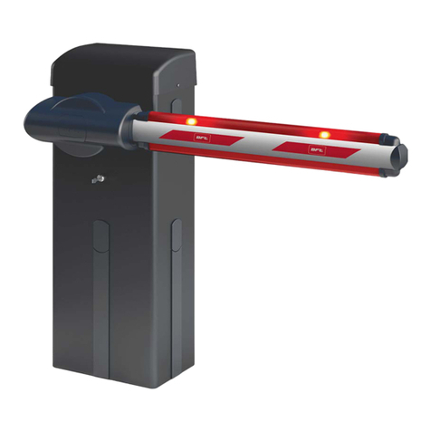
BFT GIOTTO BT A ULTRA 36 User manual


GENERALITÀ
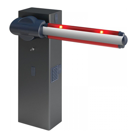
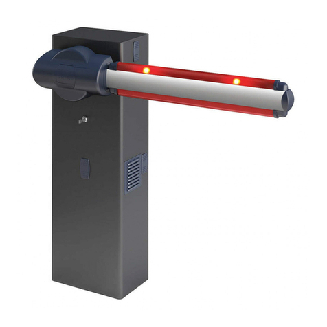
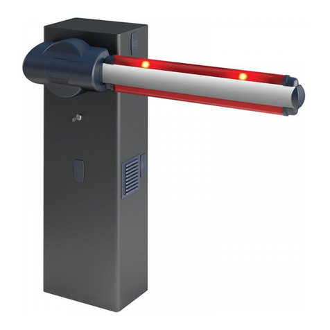
Barriera elettromeccanica compatta adatta a limitare aree private, parcheggi, accessi per uso esclusivamente veicolare. Disponibili per passaggi da 2 a 6 metri. Fine-
corsa elettronici regolabili, garantiscono la corretta posizione d’arresto dell’asta.
Lo sblocco di emergenza per la manovra manuale è comandato da una serratura con chiave personalizzata.
La barriera viene sempre fornita predisposta per il montaggio a sinistra. In caso di necessità è comunque possibile invertire il senso di apertura con semplici operazioni.
La base di fondazione mod. CBO (a richiesta) agevola l’installazione della barriera.
Apposite predisposizioni facilitano l’installazione degli accessori.
Il quadro comandi MERAK viene fornito dal costruttore con settaggio standard. Qualsiasi variazione deve essere impostata mediante display incorporato o mediante
programmatore universale.
Supporta completamente i protocolli EELINK e U-LINK.
Le caratteristiche principali sono:
- Controllo di 1 motore in bassa tensione
- Rilevamento ostacoli
- Ingressi separati per le sicurezze
- Ingressi di comando congurabili
- Ricevitore radio incorporato rolling-code con clonazione trasmettitori.
La scheda è dotata di una morsettiera di tipo estraibile per rendere più agevole la manutenzione o la sostituzione.
GENERAL OUTLINE
Compact electromechanical barrier suitable for limiting private areas, parkings, access areas for vehicles only. Available for passageways from 2 to 6 metres. Adjust-
able electronic limit switches, they guarantee correct boom stopping position.
The emergency release device for manual manoeuvre is controlled by a personalised key lock.
The barrier is always supplied for left-hand side tting. However, when necessary, the opening direction can be reversed by means of simple operations.
The CBO mod. foundation base (on request) makes barrier installation easier.Appropriate ttings make it easy to install accessories.
The MERAK control panel is supplied by the manufacturer with standard setting. Any change must be set by means of the incorporated display or by means of the
universal programmer.
Fully supports EELINK and U-LINK protocols.
Its main features are:
- Control of 1 low-voltage motor
- Obstacle detection
- Separate inputs for safety devices
- Congurable command inputs
- Built-in radio receiver rolling code with transmitter cloning.
The board has a terminal strip of the removable kind to make maintenance or replacement easier.
GENERALITES
Barrière électromagnétique compacte adaptée pour limiter les zones privées, les parkings, les accès uniquement prévus pour les véhicules. Disponible pour des
passages de 2 à 6 mètres. Les ns de course électroniques réglables garantissent la position correcte d’arrêt de la lisse.
Le déblocage d’urgence pour permettre la manœuvre manuelle est commandé par une serrure accompagnée d’une clé personnelle.
La barriere est toujours fourni déjà prédisposé pour le montage à gauche.
En cas de besoin, il est cependant possible d’inverser le sens d’ouverture par le biais d’opérations simples.
La base de fondation mod. CBO (sur demande) facilite l’installation de la barrière.
Des prédispositions spéciales facilitent l’installation des accessoires sans besoin de percer.
Le tableau de commandes MERAK est fourni par le fabricant avec un réglage standard. Toute modication doit être programmée à l’aide de l’acheur incorporé
ou à l’aide d’un programmateur universel.
Il prend complètement en charge les protocoles EELINK et U-LINK.
Les caractéristiques principales sont:
- Contrôle d’1 moteur en basse tension
- Détection obstacle
- Entrées séparées pour les dispositifs de sécurité
- Entrées de commande congurables
- Récepteur radio intégré rolling-code avec clonage des émetteurs.
La carte est munie d’un bornier extractible , pour faciliter les opérations d’entretien ou le remplacement.
ALLGEMEINES
Kompakte elektromechanische Schranke zum Absperren von Privatgrundstücken, Parkplätzen oder Zufahrten. Erhältlich für Durchfahrtbreiten von 2 bis 6 Metern.
Einstellbare elektronische Endlagenschalter garantieren dafür, dass der Baum an der richtigen Stelle anhält. Die Notfallentriegelung für die Handbedienung wird
durch über ein Schloss veranlasst, in das nur ein individueller Schlüssel passt.
Der Fahrzeugschranken Ist bei der Lieferung standardmäßig für den linksseitigen Aufbau ausgelegt.
Bei Bedarf kann die Önungsrichtung jedoch mit einfachen Handgrien umgekehrt werden.
Die Grundplatte des Modells CBO (auf Anfrage erhältlich) erleichtert die Schrankeninstallation.
Bereits vorhandene Vorrichtungen vereinfachen die Zubehörmontage, ohne dass Bohrungen notwendig sind.
DieSteuerungMERAKwirdvomHerstellermitStandardeinstellungengeliefert,dieaufdemintegriertenDisplayodermittelsUniversal-Programmiergerätänderbarsind.
Unterstützt die Protokolle EELINK und U-LINK.
Die Haupteigenschaften sind:
- Kontrolle eines Niederspannungsmotors
- Hinderniserfassung
- Separate Eingänge für die Sicherheitsvorrichtungen
- kongurierbare Steuerungseingänge
- integrierte Rolling-Code-Funkempfänger mit Sender-Clonung
Die Karte weist zur Vereinfachung der Wartungs- und Ersetzungsarbeiten eine abnehmbare Klemmleiste auf.
GENERALIDADES
Barrera electromecánica compacta adecuada para limitar áreas privadas, aparcamientos y accesos para uso exclusivamente vehicular. Disponible para aberturas de
paso de 2 a 6 metros. La correcta posición de bloqueo del asta resulta garantizada por unos nes de carrera electromecánicos regulables. El desbloqueo de emer-
gencia para la maniobra manual se activa por medio de una cerradura con llave personalizada.
La barréras se suministra siempre predispuesto para ser montado a la izquierda. En caso de necesidad, es posible invertir el sentido de apertura con extrema facilidad.
La base de cimentación mod. CBO (disponible a petición) facilita la instalación de la barrera.
Se han previsto una serie de predisposiciones para facilitar la instalación de los accesorios sin necesidad de efectuar agujeros.
El cuadro de mandos MERAK es suministrado por el constructor con conguración estándar. Cualquier variación debe congurarse mediante display incorporado
o mediante programador universal.
Soporta completamente los protocolos EELINK y U-LINK.
Las características principales son:
- Control de 1 motor en baja tensión
- Detección obstáculos
- Entradas separadas para los dispositivos de seguridad
2 GIOTTO BT A ULTRA 36
D814017 2FA00_02
17
17
19
19
ISTRUZIONI D’USO E DI INSTALLAZIONE
INSTALLATION AND USER’S MANUAL
INSTRUCTIONS D’UTILISATION ET D’INSTALLATION
INSTALLATIONS-UND GEBRAUCHSANLEITUNG
INSTRUCCIONES DE USO Y DE INSTALACION
GEBRUIKS- EN INSTALLATIEAANWIJZINGEN
AUTOMATISMOELETTROMECCANICO PER BARRIERA VEICOLARE
ELECTROMECHANICAL CONTROL DEVICE FOR VEHICULAR BARRIERS
AUTOMATISMEELECTROMECANIQUE POUR BARRIERE POUR VÉHICULES
ELEKTROMECHANISCHER ANTRIEB FÜR FAHRZEUGSCHRANKEN
AUTOMATISMOSELECTROMECANICOS PARA BARRÉRAS VEHICULAR
ELEKTROMECHANISCH AUTOMATISERINGSSYSTEEMVOOR SLAGBOOM
Attenzione! Leggere attentamentele“Avvertenze” all’interno!Caution! Read “Warnings”insidecarefully!Attention!Veuillez lire attentivementlesAvertissementsqui setrouvent à l’intérieur!
Achtung!BittelesenSie aufmerksamdie„Hinweise“im Inneren!¡Atención¡ Letop! Leesde “Waarschuwingen” aande binnenkantzorgvuldig!
M10x25 GROWER
Ø10,5
GIOTTO BT A ULTRA 36
COMPOSIZIONE DEL KIT - KIT COMPOSITION - COMPOSITION DU KIT
ZUSAMMENSETZUNG DES BAUSATZES - COMPOSICIÓN DEL KIT- SAMENSTELLING VAN DE KIT
Ø10
Muro
Wall
Mural
Mauer
Pared
Muur
ATTREZZATURE - EQUIPMENT- OUTILS - AUSRÜSTUNG-EQUIPOS - UITRUSTING
3 mm
PH1/PH2
PH1/PH2
10/13/17
Nonin dotazione
Notsupplied
Ne sontpasfournis
Nichtimlieferum
No asignadas enelequipamientobase
Nietmeegeleverd
- Entradas de mando congurables
- Receptor radio incorporado rolling-code con clonación de transmisores.
La tarjeta cuenta con tablero de bornes desmontable para facilitar aún más su mantenimiento o sustitución.
ALGEMEEN
Compacte elektromechanische slagboom geschikt voor het afzetten van privégebieden, parkeerplaatsen, toegangen die alleen door voertuigen gebruikt worden.
Beschikbaar voor doorgangen van 2 tot 6 meter. Afstelbare elektronische aanslagen garanderen de correcte stilstandspositie van de boom. De nood-deblokkering
voor de handmatige manoeuvre wordt bestuurd door een slot met gepersonaliseerde sleutel.
De barrière wordt altijd geleverd met voorbereiding voor de montage links. In geval van noodzaak is het hoe dan ook mogelijk de openingsrichting met eenvoudige
handelingen om te keren. De ankerplaat mod. CBO (op aanvraag) vereenvoudigt de installatie van de slagboom. Speciale voorbereidingen maken het makkelijker
de accessoires te installeren.
Het bedieningspaneel MERAK wordt door de fabrikant met standaard instellingen geleverd. Iedere willekeurige verandering moet worden ingesteld door middel
van het geïntegreerde display of door middel van een universele programmabesturing.
Ondersteunt de protocollen EELINK en U-LINK.
De voornaamste kenmerken zijn:
- Controleert 1 laagspanningsmotor
- Obstakelwaarneming
- Gescheiden ingangen voor de veiligheden
- Congureerbare bedieningsingangen
- Geïntegreerde radio-ontvanger rolling-code met klonering zenders.
De kaart is uitgerust met een verwijderbare verbindingsstrip om het onderhoud of de vervanging eenvoudiger te maken.
GIOTTO BT A ULTRA 36 - 3
D814017 2FA00_02

A
B
2x1 mm
2
3x1,5 mm
2
2-6 m
2x 0,75 mm
2
3x 0,75 mm
2
3x 0,75
5
x
0
,
7
5
m
m
2
220 340
1040
807 118
870
120
*
*
*
*
*
5
4
m
m
1
1
8
m
m
DIMENSIONI - DIMENSIONS - DIMENSIONS -ABMESSUNGEN -
DIMENSIONES -
AFMETINGEN
*
Non in dotazione, Not supplied, Ne sont pas fournis
Nicht im lieferum, No asignadas en el equipamiento base, Niet meegeleverd
default
PREDISPOSIZIONE CAVI - CABLE ARRANGEMENT - PRÉDISPOSITION DES CÂBLES
VORBEREITUNG DER KABEL - PREPARACIÓN DE LOS CABLES - PREDISPOSITIE KABELS
barriera sinistra
LH barrier
barrière gauche
linke Schranke
barrera izquierda
barrière links
barriera destra
RH barrier
barrière droite
rechte Schranke
barrera derecha
barrière rechts
4 GIOTTO BT A ULTRA 36
D814017 2FA00_02


G
2
1
CONNESSIONI CENTRALE DI COMANDO - CONTROL UNIT CONNECTIONS - CONNEXIONS UNITÉ DE COMMANDE
ANSCHLÜSSE STEUERGERÄT - CONEXIÓN A LA CENTRAL DE CONTROL -VERBINDINGEN BEDIENINGSEENHEID
8 GIOTTO BT A ULTRA 36
D814017 2FA00_02
H
725150 70
24V ~
2
1TX1 2
1
RX1
4
5
3
SAFE 1
= 0 SAFE 1
= 1
725150 70
24V ~
Vsafe
7352
2
1TX1 2
1
RX1
4
5
3
1
3 4
2
5
26 27 26 27
AUX 3 = 12
AUX 0 = 6
AUX 3 = 12
!
24V
20 21
AUX0 - 24V
(MAX 1A)
20 21
24V
AUX 0 = 0
AUX 0 = 1
AUX 0 = 2
AUX 0 = 3
AUX 0 = 4
AUX 0 = 5
AUX 0 = 7
AUX 0 = 8
AUX 0 = 9
AUX 0 = 10
AUX 0 = 12
AUX 0 = 13
AUX 0 = 14
AUX 3 = 0
AUX 3 = 2
AUX 3 = 3
AUX 3 = 4
AUX 3 = 5
AUX 3 = 6
AUX 3 = 7
AUX 3 = 8
AUX 3 = 9
AUX 3 = 10
AUX 3 = 12
AUX 3 = 13
AUX 3 = 14
AUX 3 = 1
24 V
SCA
26 27
26 27 50 51
Connessione A Sistema Gestione Parcheggi, Connection To Car-park Management System, Connexion Au Système De Gestion Des Parkings, Anschluss An Das
Parkplatzbewirtschaftungssystem, Conexion Al Sistema De Gestion De Aparcamientos, Erbinding Met Beheersysteem parkeerplaatsen
Fotocellule non vericate (Check ogni 6 mesi)
Photocells not checked (Check every 6 months)
Photocellules non vériées (contrôle tous les 6 mois)
Fotozellen nicht überprüft (alle 6 Monate überprüfen)
Fotocélulas no controladas (Control cada 6 meses)
Fotocellen niet gecontroleerd (Check elke 6 maanden)
Fotocellula vericata
Photocell checked
Photocellule vériée
Fotozelle überprüft
Fotocélula controlada
Fotocel gecontroleerd
GIOTTO BT A ULTRA 36 - 9
D814017 2FA00_02

G
I
F3 1,25A T
F4
1,25A T
10 11 20 21 26 27 41 42 43 50 51 52 60 61 62 70 71 72 73 74 75
M1
+
-
AUX 3
(MAX 24V 1A)
AUX
+ REF SW
RIFC
RIFO
24V-2~/+24V
VSafe 24V-2~/+24V
COM
IC 1
IC 2
NO
NC
NC
NO
SAFE 1
STOP
COM
FAULT 1
SAFE 2
FAULT 2
NC
NC
NC
S1
S2
S3
+
-
OK
!
AUX 0 - 24V
(MAX 1A)
24V
L N
LN
220-230V ~
*
!
24V~ 220-230V~*
*F1:
230V: 2 AT
120V: 2 AT
F1*
24V-1~/-24V
10 11 20 2126 27 41 42 43 50 51 52 60
6
1
L N
OPEN
CLOSE
S1
S2
+S1
+
-S2
-
X1
X1 X1
X1
OPEN
CLOSE STOP
STOP
*
*1
*2
1
0
1
1
L
N
COLLEGAMENTI MORSETTIERA, TERMINAL BOARD WIRING, BRANCHEMENTS SUR LE BORNIER, ANSCHLÜSSE KLEMMLEISTE,
CONEXIONES TABLERO DE BORNES, AANSLUITINGEN AANSLUITKAST.
Connettore scheda opzionale / Optional board connector,
Connecteur carte facultative / Steckverbinder Zusatzkarte,
Conector de la tarjeta opcional / Connector optionele kaart.
Display + tasti programmazione / Display plus programming keys,
Acheur et touches de programmation / Display und Programmierungstasten,
Pantalla más botones de programación / Display meerdere toetsen programmeur.
Alimentazione
Power supply
Alimentation
Stromversorgung
Alimentación
Voeding
Motore / Motor
moteur/Motor
Eindaanslag
Encoder
Collegamento gruppo necorsa
Limit switch assembly connection
Connexion groupe n de course
Anschluss Endschaltergruppe
Conexión grupo nal de carrera
Verbinding groep eindaanslagen
Alimentazione accessori
Accessories power supply
Alimentation des accessoires
Stromversorgung Zubehör
Alimentación accesorios
Voeding accessoires
Comandi / Commands
Commandes/Bedienelemente
Mandos/ Commando’s
Sicurezze
Safety devices
Sécurités
Sicherheitsvorrichtungen
Dispositivos de seguridad
Veiligheden
Connettore programmatore palmare,
Palmtop programmer connector,
Connecteur programmateur de poche,
Steckverbinder Palmtop-Programmierer,
Conector del programador de bolsillo,
Connector programmeerbare palmtop.
Connettore encoder
Encoder connector
Connecteur encodeur
Steckverbindung Encoder
Conector Encoder
Connector encoder
*(L) *1(N) *2
Marrone Blu Giallo/ Verde
Brown Bleu Yellow/ Green
Marron Bleu Jaune/ Vert
Braun Blau Gelb/ Grün
Maron Azul Amarillo/ Verde
bruin blauw Geel/ Groen
10 GIOTTO BT A ULTRA 36
D814017 2FA00_02
lang
Dir
ITA
fra
deu
eng
esp
Dx
Sx Sx :
barriera sinistra
ar :
funzionamento
automatico,
residenziale
sr :
funzionamento
semi-aut.,
residenziale
ac :
funzionamento
automatico,
condominiale
Sc : funzionamento
semi-automatico,
condominiale
Ind : funzionamento
a uomo presente
Dx :
barriera destra
AR
preset
tipo
45-60
20-45
e
tasto nascosto
rilascia
O 01
tasto desiderato
telec
sr
ac
sc
ind
fine
FIG. 1
x1
0--- 10-- 150- 1520 ok
PRESET DEFAULT ar sr ac sc ind
PARAMETRI
Tempo chiusura automatica [s] 10 10 10 5 5 5
LOGICHE
Tempo Chiusura Automatica 1 1 0 1 0 0
Movimento passo passo 1 1 0 1 0 0
Preallarme 0 0 0 1 1 0
Uomo presente 0 0 0 0 0 1
Blocca impulsi in apertura 1 0 0 1 1 0
*** Inserimento password.
Richiesta con logica Livello Protezione impostata a 1, 2, 3, 4
***
GIOTTO BT A ULTRA 36 - 11
D814017 2FA00_02

SIMPLIFIED MENU (FIG .1)
Dir
ITA
fra
deu
eng
esp
ar
sr
ac
Sc
Ind
AR
preset
O 01
sr
ac
sc
ind
:
semiautomatic
operation,
residential
:automatic
operation,
commercial
:
semiautomatic
operation,
commercial
:dead man
operation
lh:
right barrier
rh:
lh
rh
left barrier
:
automatic
operation,
residential
release
end
desidered button
e
hidden button
re otes
x1
0--- 10-- 150- 1520 ok
Exit Menù
Conrm/Switch on display
Scroll up
Scroll down
language
***
type
KEY
45-60
20-45
PRESET DEFAULT ar sr ac sc ind
PARAMETERS
Automatic closing time [s]
10 10 10 5 5 5
LOGIC
Automatic Closing Time 1 1 0 1 0 0
Step-by-step movement 1 1 0 1 0 0
Pre-alarm 0 0 0 1 1 0
Deadman 0 0 0 0 0 1
Block pulses during opening 1 0 0 1 1 0
*** Password entry.
Request with Protection Level logic set to 1, 2, 3, 4
12 GIOTTO BT A ULTRA 36
D814017 2FA00_02
MENU SIMPLIFIÉ (FIG .1)
Sortir du menu
Con firmation /
Allumage aicheur
Monter
Descendre
ITA
fra
deu
eng
esp
language
x1
0--- 10-- 150- 1520 ok
:fonctionnement
automatique, résidentiel
:
fonctionnement
semi-automatique,
résidentiel
:fonctionnement
automatique, collectif
:fonctionnement
semi-automatique,collectif
:fonctionnement à
homme présent
Dir
ar
sr
ac
Sc
Ind
AR
preset
e
O 01
telec
sr
ac
sc
ind
fin
touche cachee
relacher
touche desiree
drt
:
barrière gauche
gch
:barrière droite
gch
drt
***
typ
45-60
20-45
LÉGENDE
PRESET DEFAULT ar sr ac sc ind
PARAMETRES
Temps fermeture automatique [s]
10 10 10 5 5 5
LOGIQUES
Temps fermeture automatique 1 1 0 1 0 0
Mouvement pas à pas 1 1 0 1 0 0
Préalarme 0 0 0 1 1 0
Homme-présent 0 0 0 0 0 1
Verrouillage impulsions à l’ouverture 1 0 0 1 1 0
*** Saisie du mot de passe.
Demande avec logique Niveau Protection congurée sur
1, 2, 3, 4
GIOTTO BT A ULTRA 36 - 13
D814017 2FA00_02


Retorno al menú
principal
Conrmación/
Encendido pantalla
Desplazar hacia arriba
Desplazar hacia abajo
: funcionamiento automático,
en viviendas
funcionamiento semi-aut,
en viviendas
: funcionamiento automático,
en edicios
: funcionamiento semi-aut,
en edicios
: funcionamiento con hombre
presente
MENUS SEMPLIFICADO (FIG .1)
Dir
ITA
fra
deu
eng
esp
ar
sr:
ac
Sc
Ind
AR
preset
O 01
sr
ac
sc
ind
fine
IDIO A
anad start
suelte
tecla deseada
RADIO
x1
0--- 10-- 150- 1520 ok
:
barrera izquierda
:
barrera derecha
IZQ
DER
IZQ
DER
***
tipo
45-60
20-45
LEYENDA
PRESET DEFAULT ar sr ac sc ind
PARÁMETROS
Tiempo cierre automático [s] 10 10 10 5 5 5
LÓGICA
Tiempo de Cierre Automático 1 1 0 1 0 0
Movimiento paso a paso 1 1 0 1 0 0
Preallarm 0 0 0 1 1 0
Hombre presente 0 0 0 0 0 1
Bloqueo impulsos en fase de apertura 1 0 0 1 1 0
*** Introducción contraseña.
Solicitud con lógica Nivel Protección congurada a 1, 2, 3, 4
GIOTTO BT A ULTRA 36 - 15
D814017 2FA00_02

: automatische bediening,
woon-
: functionerende semi-aut.,
woon-
: automatische bediening,
condominium
: semi-automatische bediening,
condominium
: dodemansbediening
SIMPLIFIED MENU (FIG.1)
Terug keer naar het
hoofdmenu
Bevestig /
Aanschakeling display
Doorloop op
Doorloop neer
LEGENDE
Dir
ITA
fra
deu
eng
esp
ar
sr
ac
Sc
Ind
AR
preset
e
O 01
sr
ac
sc
ind
language
re otes
hidden button
release
desidered button
end
:
linker slagboom
:rechter slagboom
lh
rh
lh
rh
x1
0--- 10-- 150- 1520 ok
***
45-60
20-45
type
PRESET DEFAULT ar sr ac sc ind
PARAMETER
Tijd automatische sluiting [sec.] 10 10 10 5 5 5
LOGICA’S
Tijd Automatische Sluiting 1 1 0 1 0 0
Stap voor stap beweging 1 1 0 1 0 0
Vooralarm 0 0 0 1 1 0
Persoon aanwezig 0 0 0 0 0 1
Blokkeert impulsen bij opening 1 0 0 1 1 0
*** Password invoeren.
Aanvraag met logica Beschermingsniveau ingesteld op 1, 2, 3, 4
16 GIOTTO BT A ULTRA 36
D814017 2FA00_02
fine-end-fin
PARA
cal. ap. - open cal.
cal. ouv. - off. kal. PRG ok
[60]
+
OK
OK
P1 +
P2 -
vel. ap. - op. speed
- vit ouv -
offnungsgeschv
vel. ch. - cl. speed
- vit ferm -
schliebgeschv
PRG ok
[45]
OK P1 +
P2 -
PRG ok
[45]
OK P1 +
P2 -
PRG ok
OK P1 +
P2 -
[45]
sp.decel - esp.decel. -
erlangsamungstrecke
dist.decel - esp.decel
accel. - acceler -
accel-beschleunigung
PRG ok
OK P1 +
P2 -
[55]
PRG ok
OK P1 +
P2 -
[2]
x 2
x 2
OK
default
default
default
default
default
default
cal. ch-clos calib.
-cal.ferm.-sch.kal
-cal.cie
J
Modicare i valori seguenti no a raggiungere il movimento dell’asta desiderato.
Edit the following values until you are happy with boom movement.
Modiez les valeurs suivantes jusqu’à ce que la barre se déplace de la façon voulue.
Die folgenden Werte verändern, bis die gewünschte Bewegung der Stange erzielt wird.
Modicar los siguientes valores hasta lograr el movimiento deseado del mástil.
Onderstaande waarden wijzigen tot de beweging van de gewenste stang bereikt wordt.
REGOLAZIONI PRELIMINARI, PRELIMINARY ADJUSTMENTS, RÉGLAGES PRÉALABLES, VORBEREITENDE EINSTELLUNGEN,
REGULACIONES PRELIMINARES, INLEIDENDE REGELS
GIOTTO BT A ULTRA 36 - 17
D814017 2FA00_02

E
K
UNIDA
B EBA U-LINK 485
50 51 52
CC2
70 71 72 73 74 75
SAFE 1 = 1
SAFE 2 = 7 (≥6) SAFE 2 SLAVE = SAFE 2 MASTER
50 51 52 6160
TX1 RX1
CC1
62 63 64 65 70 71 72 73 74 75
START STOP
MAX 250m
B EBA U-LINK 485
F3 1,25A T
10 11 20 21 26 27 41 42 43 50 51 52 60 61 62 70 71 72 73 74 75
S1
S2
S3
+
-
OK
F3 1,25A T
10 11 20 21 26 27 41 42 43 50 51 52 60 61 62 70 71 72 73 74 75
S1
S2
S3
+
-
OK
8888
L
M
S1
S2
S3
+
-
OK
S1
S2
S3
+
-
OK
70 71
COM
STOP
S1
S2
S3
+
-
OK
S1
S2
S3
+
-
OK
8888 rst8
8888
. ...
1 2 3 4
65
!
<3s
+
MASTER SLAVE
CC1
(BAR)
CC2
(BAR)
ON
OFF
SCHEDA DI ESPANSIONE
EXPANSION BOARD
CARTE D’EXPANSION
ERWEITERUNGSKARTE
TARJETA DE EXPANSIÓN
UITBREIDINGSKAART
Programmatore palmare universale
Universal palmtop programmer
Programmateur de poche universe
Universellen Palmtop-Programmier
Programador de bolsillo universal
Programmeerbare Universele Palmtop
INDIRIZZO=0
address=0
adresse=0
adresse=0
direccion=0
odo seriale=3
serial ode=3
ode serie=3
serieller odus=3
odo seria=3
INDIRIZZO=0
address=0
adresse=0
adresse=0
direccion=0
odo seriale=2
serial ode=2
ode serie=2
serieller odus=2
odo seria=2
PER IL COLLEGAMENTO DI PIÙ FOTOCELLULE FARE RIFERIMENTO ALLA FIG. P TO CONNECT SEVERAL PHOTOCELLS, REFER TO FIG. P
POUR BRANCHER PLUSIEURS PHOTOCELLULES CONSULTEZ LA FIG. P BITTE NEHMEN SIE FÜR DEN ANSCHLUSS MEHRERER FOTOZELLEN AUF FIG. P BEZUG
PARA LA CONE
XIÓN DE VARIAS FOTOCÉLULAS CONSULTAR LA FIG. P VOOR HET VERBINDEN VAN MEERDERE FOTOCELLEN ZIE FIG. P
18 GIOTTO BT A ULTRA 36
D814017 2FA00_02
N
50 51 52 70 71 72 73 74 75
24V -
24V +
24 VSafe+
COM
SAFE 1
SAFE 2
STOP
FAULT 1
FAULT 2
NC
NC
NC
1-S 2-S 3-S 4-S 5-S 6-S (SCS-MA)
SAFE 1
1
2
1
2
3
4
5
51 TX1 RX1
Bar 1
1
2
3
4
5
6
1
2
1
2
3
4
5
52
50 TX1 RX1
1
2
1
2
3
4
5
TX1 RX1
1
2
1
2
3
4
5
TX2 RX2
1
2
1
2
3
4
5
TX1 RX1
1
2
1
2
3
4
5
TX2 RX2
1
2
1
2
3
4
5
TX3 RX3
1
2
1
2
3
4
5
TX1 RX1
1
2
1
2
3
4
5
TX2 RX2
1
2
1
2
3
4
5
TX3 RX3
1
2
1
2
3
4
5
TX4 RX4
Bar 1
1
2
3
4
5
Bar 2
1
2
3
4
5
Bar 1
1
2
3
4
5
Bar 2
1
2
3
4
5
Bar 3
1
2
3
4
5
Bar 1
1
2
3
4
5
Bar 2
1
2
3
4
5
Bar 4
1
2
3
4
5
Bar 3
1
2
3
4
5
Bar 1
1
2
3
4
5
6
6
6
6
66
6
66
6
1
2
1
2
3
4
5
TX1 RX1
Bar 1
1
2
3
4
5
6
1
2
1
2
3
4
5
TX1 RX1
1
2
1
2
3
4
5
TX1 RX1
1
2
1
2
3
4
5
TX2 RX2
1
2
1
2
3
4
5
TX1 RX1
1
2
1
2
3
4
5
TX2 RX2
1
2
1
2
3
4
5
TX3 RX3
1
2
1
2
3
4
5
TX1 RX1
1
2
1
2
3
4
5
TX2 RX2
1
2
1
2
3
4
5
TX3 RX3
1
2
1
2
3
4
5
TX4 RX4
Bar 1
1
2
3
4
5
Bar 2
1
2
3
4
5
Bar 1
1
2
3
4
5
Bar 2
1
2
3
4
5
Bar 3
1
2
3
4
5
Bar 1
1
2
3
4
5
Bar 2
1
2
3
4
5
Bar 4
1
2
3
4
5
Bar 3
1
2
3
4
5
Bar 1
1
2
3
4
5
6
6
6
6
66
6
66
6
SAFE1 = 1,3,5 SAFE1 = 0,2,4
SAFE1 = 7
SAFE1 = 8
1 PHOT / 1 PHOT OP / 1 PHOT CL
2 PHOT / 2 PHOT OP / 2 PHOT CL
3 PHOT / 3 PHOT OP / 3 PHOT CL
4 PHOT / 4 PHOT OP / 4 PHOT CL
BAR 8K2
1 BAR
1 BAR
2 BAR
3 BAR
4 BAR
50
52
50
52
50
52
50
52
50
52
50
52
50
52
50
52
50
52
50
51
50
51
50
51
50
51
50
51
50
51
50
51
50
51
50
51
50
51
50
51
50
70
72
70
72
73
70
70
70
70
70
70
72
72
72
73
2-S
1-S
3-S
73
2-S
1-S
3-S
5-S
4-S
6-S
73
51
51
50
51
50
51
50
51
50
51
50
51
50
51
50
51
50
51
50
51
50
52
52
52
52
52 52
52 52
52 52
72
70
72
70
73
72
70
51
50
70
73
72
70
4-S
5-S
6-S
70
73
72
70
1-S
2-S
4-S
5-S
3-S
70
73
6-S
70
72 8,2Kohm 5%
SAFETY EDGE SAFETY EDGE
1
SAFE1 = 6
3
2
5
4
SAFE 2
1
2
1
2
3
4
5
51 TX1 RX1
Bar 1
1
2
3
4
5
6
1
2
1
2
3
4
5
52
50 TX1 RX1
1
2
1
2
3
4
5
TX1 RX1
1
2
1
2
3
4
5
TX2 RX2
1
2
1
2
3
4
5
TX1 RX1
1
2
1
2
3
4
5
TX2 RX2
1
2
1
2
3
4
5
TX3 RX3
1
2
1
2
3
4
5
TX1 RX1
1
2
1
2
3
4
5
TX2 RX2
1
2
1
2
3
4
5
TX3 RX3
1
2
1
2
3
4
5
TX4 RX4
Bar 1
1
2
3
4
5
Bar 2
1
2
3
4
5
Bar 1
1
2
3
4
5
Bar 2
1
2
3
4
5
Bar 3
1
2
3
4
5
Bar 1
1
2
3
4
5
Bar 2
1
2
3
4
5
Bar 4
1
2
3
4
5
Bar 3
1
2
3
4
5
Bar 1
1
2
3
4
5
6
6
6
6
66
6
66
6
1
2
1
2
3
4
5
TX1 RX1
Bar 1
1
2
3
4
5
6
1
2
1
2
3
4
5
TX1 RX1
1
2
1
2
3
4
5
TX1 RX1
1
2
1
2
3
4
5
TX2 RX2
1
2
1
2
3
4
5
TX1 RX1
1
2
1
2
3
4
5
TX2 RX2
1
2
1
2
3
4
5
TX3 RX3
1
2
1
2
3
4
5
TX1 RX1
1
2
1
2
3
4
5
TX2 RX2
1
2
1
2
3
4
5
TX3 RX3
1
2
1
2
3
4
5
TX4 RX4
Bar 1
1
2
3
4
5
Bar 2
1
2
3
4
5
Bar 1
1
2
3
4
5
Bar 2
1
2
3
4
5
Bar 3
1
2
3
4
5
Bar 1
1
2
3
4
5
Bar 2
1
2
3
4
5
Bar 4
1
2
3
4
5
Bar 3
1
2
3
4
5
Bar 1
1
2
3
4
5
6
6
6
6
66
6
66
6
SAFe 2= 1,3,5 SAFe 2 = 0,2,4
SAFe 2 = 6
SAFe 2 = 7
SAFe 2 = 8
1 PHOT / 1 PHOT OP / 1 PHOT CL
2 PHOT / 2 PHOT OP / 2 PHOT CL
3 PHOT / 3 PHOT OP / 3 PHOT CL
4 PHOT / 4 PHOT OP / 4 PHOT CL
BAR 8K2
1 BAR
1 BAR
2 BAR
3 BAR
4 BAR
50
52
50
52
50
52
50
52
50
52
50
52
50
52
50
52
50
52
50
51
50
51
50
51
50
51
50
51
50
51
50
51
50
51
50
51
50
51
50
51
50
70
74
70
74
75
70
70
70
70
70
70
74
74
74
75
2-S
1-S
3-S
75
2-S
1-S
3-S
5-S
4-S
6-S
75
51
51
50
51
50
51
50
51
50
51
50
51
50
51
50
51
50
51
50
51
50
52
52
52
52
52 52
52 52
52 52
74
70
74
70
75
74
70
51
50
70
75
74
70
4-S
5-S
6-S
70
75
74
70
1-S
2-S
4-S
5-S
3-S
70
75
6-S
70
74 8,2Kohm 5%
SAFETY EDGE SAFETY EDGE
1 3
2 4
5
TEST OFFTEST ON
TEST OFFTEST ON
Numero massimo di dispositivi verifcati: 6 (ma non più di 4 per tipo),
Maximum number of tested devices: 6 (but no more than 4 per type),
Nombre maximum dispositif vérifés: 6 (mais pas plus de 4 par type),
Max. Anzahl der überprüften Geräte: 6 (jedoch nicht mehr als 4 je Typ),
Número máximo dispositivos comprobados: 6 (pero no más de 4 por tipo),
Maximumaantal“trusted devices”: 6 (maar niet meer dan 4 per type)
GIOTTO BT A ULTRA 36 - 19
D814017 2FA00_02

ITALIANO
ACCESSO AI MENU Fig. 2
stat
password
-+
-+
OK
vers
bft . . .
+/-
OK
0000
+/-
+/-
n. an
OK
OK
0--- 10-- 150- 1520 prg
00
n. teleco
-+
err
Elenco ultimi 30 errori
+/-
ALT SEGUIRE IL MANUALE
x2
0--- 10-- 150- 1520 ok
01.33
02.01
........
30.15
*** Inserimento password.
Richiesta con logica Livello Protezione
impostata a 1, 2, 3, 4
Codice
diagnostica
Descrizione Note
STRE Attivazione ingresso start esterno START E
STRI Attivazione ingresso start interno START I
OPEN Attivazione ingresso OPEN
CLS Attivazione ingresso CLOSE
TI EAttivazione ingresso TIMER
STOP Attivazione ingresso STOP
PHOT
Attivazione ingresso fotocellula PHOT o se congurato come
fotocellulavericataAttivazionedell’ingressoFAULTassociato
PHOP Attivazione ingresso fotocellula in apertura PHOT OP o se
congurato come fotocellula vericata attiva solo in aper-
tura Attivazione dell’ingresso FAULT associato
PHCL Attivazione ingresso fotocellula in chiusura PHOT CL o se
congurato come fotocellula vericata attiva solo in chiu-
sura Attivazione dell’ingresso FAULT associato
BAR Attivazione ingresso costa BAR o se congurato come costa
sensibile vericata Attivazione dell’ingresso FAULT associato
BAR 2 AttivazioneingressocostaBARsumotoreslave(connessione
ante contrapposte) o se congurato come costa sensibile
vericata Attivazione dell’ingresso FAULT associato
SWC Attivazione ingresso necorsa chiusura del motore SWC
SWO Attivazione ingresso necorsa apertura del motore SWO
refo Attivazione ingresso riferimento in apertura
refc Attivazione ingresso riferimento in chiusura
ER01 Test fotocellule fallito Vericare collegamento fotocellule e/o impostazioni
logiche
ER02 Test costa fallito Vericare collegamento coste e/o impostazioni logiche
ER03 Test fotocellule apertura fallito Vericare collegamento fotocellule e/o impostazione
parametri/logiche
ER04 Test fotocellule chiusura fallito Vericare collegamento fotocellule e/o impostazione
parametri/logiche
ER05 Test costa su motore slave fallito (connessione ante
contrapposte) Vericare collegamento coste e/o impostazioni para-
metri/logiche
ER06 Test costa 8k2 fallito Vericare collegamento coste e/o impostazioni para-
metri/logiche
ER1x*Errore test hardware scheda -Vericare collegamenti al motore
-
Problemihardwareallascheda(contattarel’assistenzatecnica)
ER2x*Errore encoder vericare il cablaggio e la schedina encoder, eventual-
mente il verso motore e resettare la scheda
ER3x*Inversione per ostacolo - Amperostop Vericare eventuali ostacoli lungo il percorso
ER4x*Termica Attendere il rareddamento dell’automazione
ER5x*Errore comunicazione con dispositivi remoti Vericare il collegamento con i dispositivi accessori e/o
schede di espansione collegati via seriale
ER70, ER71
ER74, ER75 Errore interno di controllo supervisione sistema. Provare a spegnere e riaccendere la scheda. Se il pro-
blema persiste contattare l’assistenza tecnica.
ER72 Errore di consistenza dei parametri di centrale (Logiche
e Parametri)
Premendo Ok vengono confermate le impostazioni
rilevate. La scheda continuerà a funzionare con le
impostazioni rilevate.
E’necessario vericare le impostazioni della scheda
(Parametri e Logiche).
ER73 Errore nei parametri di D-track Premendo Ok la scheda riprenderà a funzionare con
D-track di default.
E’necessario eettuare un autoset
ErFx*errore necorsa vericare collegamenti dei necorsa
ERf3 Errore nell’impostazione degli ingressi SAFE Vericare la corretta impostazione degli ingressi SAFE,
nelfunzionamentoinbarrierecontrapposteSAFE2deve
essere congurato come costa. Fig.L
* X= 0,1,…,9,A,B,C,D,E,F
***
20 GIOTTO BT A ULTRA 36
D814017 2FA00_02
Other manuals for GIOTTO BT A ULTRA 36
1
This manual suits for next models
1
Table of contents
Languages:
Other BFT Control System manuals

BFT
BFT MOOVI ART 90 User manual

BFT
BFT DAMPY B Guide

BFT
BFT XPASS B 330/1200 L Parts list manual

BFT
BFT XPASS B 275/800C L Parts list manual

BFT
BFT STOPPY MBB 219-500.C Parts list manual

BFT
BFT XPASS B 1200C User manual

BFT
BFT RANCH C 275/600CN Guide

BFT
BFT MICHELANGELO BT A 80 User manual

BFT
BFT PHP ADA User manual

BFT
BFT STOPPY B 115/500 Parts list manual