BFT EOS User manual

Via Lago di Vico, 44
36015 Schio (VI)
Tel.naz. 0445 696511
Tel.int. +39 0445 696533
Fax 0445 696522
Internet: www.bft.it
E-mail: [email protected]
I
GB
F
D
E
P
AUTOMAZIONI PER PORTE BASCULANTI E SEZIONALI
AUTOMATION FOR OVERHEAD AND SECTIONAL GARAGE DOORS
AUTOMATION POUR PORTES BASCULANTES ET SECTIONALES
GARAGENTORANTRIEB FÜR SCHWING UND SEKTIONALTORE
AUTOMATIZACIONES PARA PUERTAS BASCULANTE Y SECCIONALES
AUTOMATIZAÇÕES PARA PORTAS BASCULANTES DE MOLAS E SECCIONAIS
EOS
ISTRUZIONI D'USO E DI INSTALLAZIONE
INSTALLATION AND USER'S MANUAL
INSTRUCTIONS D'UTILISATION ET D'INSTALLATION
MONTAGE- und BEDIENUNGSANLEITUNG
INSTRUCCIONES DE USO Y DE INSTALACION
INSTRUÇÕES DE USO E DE INSTALAÇÃO
D811325 ver. 07 20-12-04
8 027908 190642

2 -
EOS - Ver. 07
D811325_07

EOS- Ver. 07
- 3
D811325_07
Nel ringraziarVi per la preferenza accordata a questo prodotto, la ditta è
certa che da esso otterrete le prestazioni necessarie al Vostro uso. Leggete
attentamente l’opuscolo “Avvertenze”ed il “Libretto istruzioni”che
accompagnano questo prodotto in quanto forniscono importanti indicazioni
riguardanti la sicurezza, l’installazione, l’uso e la manutenzione. Questo
prodotto risponde alle norme riconosciute della tecnica e della disposizioni
relative alla sicurezza. Confermiamo che èconforme alle seguenti direttive
europee: 89/336/CEE, 73/23/CEE, 98/37/CEE (e loro modifiche successi-
ve).
1) GENERALITÀ
Il sistema EOS ècompatibile con il protocollo EElink per una rapida
installazione e manutenzione.
Esso èadatto a motorizzare porte sezionali , porte basculanti debordanti
a molle a totale rientranza e porte basculanti a contrappesi mediante un
apposito braccio di traino. L’altezza massima della porta basculante non
deve superare i 2.5 metri. L’installazione di facile esecuzione, permette un
rapido montaggio senza alcuna modifica alla porta. Il blocco in chiusura è
mantenuto dal motoriduttore irreversibile.
Questo prodotto è stato progettato per motorizzare i sopraindicati
tipi di porte. Ogni altro impiego, sarà considerato contrario all’utiliz-
zo previsto dal fabbricante che, pertanto, non potrà risultare respon-
sabile dei danni a persone, animali o cose che eventualmente ne
derivino.
2) SICUREZZA
L’automazione, se installata ed utilizzata correttamente, soddisfa il grado
di sicurezza richiesto. Tuttavia èopportuno osservare alcune regole di
comportamento per evitare inconvenienti accidentali. Prima di usare l’au-
tomazione, leggere attentamente le istruzioni d’uso e conservarle per
consultazioni future.
•Tenere bambini, persone e cose fuori dal raggio d’azione dell’automa
zione, in particolare durante il funzionamento.
•Non lasciare radiocomandi o altri dispositivi di comando alla portata dei
bambini onde evitare azionamenti involontari dell’automazione.
•Non contrastare volontariamente il movimento dell’anta.
•Non tentare di aprire manualmente la porta se non èstato sbloccato il
sistema di blocco interno tirando con l’apposita cordina collegata al
carrello, oppure attivato lo sblocco esterno (SM1 o SET/S).
•Non modificare i componenti dell’automazione.
•In caso di malfunzionamento, togliere l’alimentazione, attivare lo sbloc-
co di emergenza per consentire l’accesso e richiedere l’intervento di un
tecnico qualificato (installatore).
•Per ogni operazione di pulizia esterna, togliere l’alimentazione di rete.
•Tenere pulite le ottiche delle fotocellule ed i dispositivi di segnalazione
luminosa. Controllare che rami ed arbusti non disturbino i dispositivi di
sicurezza (fotocellule).
•Per qualsiasi intervento diretto all’automazione, avvalersi di personale
qualificato (installatore) o centro assistenza tecnica.
•Annualmente far controllare l’automazione da personale qualificato.
3) MANOVRA DI EMERGENZA
Nel caso manchi l’energia elettrica o, di avaria del sistema, per eseguire la
manovra manualmente, bisogna tirare il cordino collegato al carrello come
in fig.1. Per autorimesse prive di uscita secondaria èobbligatorio montare
un dispositivo di sblocco dall’esterno con chiave tipo il Mod. SM1 (fig.2) o
il Mod. SET/S (fig.3).
4) SOTITUZIONE DELLA LAMPADINA
La sostituzione della lampadina luce di cortesia si effettua togliendo la
copertura trasparente (Fig.4).
ATTENZIONE: Utilizzare esclusivamente lampade tipo 24V 25W max E14.
MANUALE D’USO ITALIANO

4 -
EOS - Ver. 07
D811325_07
Thank you for buying this product, our company is sure that you will be more
than satisfied with the product’s performance. The product is supplied with
a “Warnings”leaflet and an “Instruction booklet”. These should both be
readcarefullyastheyprovideimportantinformationaboutsafety,installation,
operation and maintenance. This product complies with the recognised
technical standards and safety regulations. We declare that this product is
in conformity with the following European Directives: 89/336/EEC and 73/
23/EEC, 98/37/EEC (and subsequent amendments).
1) GENERAL OUTLINE
The EOS system is compatible with the EElink protocol for fast installation
and maintenance. It is suitable for motorising sectional doors, protruding
fullyretracting spring operated overhead doors and counterweight overhead
doors provided with an appropriate towing arm. The overhead door must
not be higher than 2.5 metres. It is easy to install and fast to fit and does not
need the door to be modified. The irreversible gearmotor keeps the door
locked in the closing position. The control unit is builtin. It controls the
operation relays and the safety devices (photocell, rubber skirt) before
performing every manoeuvre.
This product was designed to motorise the types of door mentioned
above. Any other use is considered contrary to that intended by the
manufacturer who, therefore, cannot be held responsible for any
injuries to persons or animals, or damage to things which might
derive from misuse.
2) SAFETY
If correctly installed and used, this automation device satisfies the required
safety level standards. However, it is advisable to observe some practical
rules in order to avoid accidental problems. Before using the automation
device, carefully read the operation instructions and keep them for future
reference.
•Keep children, persons and things outside the automation working area,
particularly during operation.
•Keep radio control or other control devices out of children’s reach, in
order to avoid any unintentional automation activation.
•Do not intentionally oppose the leaf movement.
•Do not attempt to open the door manually, if the internal locking system
has not been released by pulling the appropriate wire connected to the
carriage, or the external lock (SM1 or SET/S) activated.
•Do not modify the automation components.
•In case of malfunction, disconnect the power supply, activate the
emergency release to gain access to the automation device and request
the assistance of a qualified technician (installer).
•Before proceeding to any external cleaning operation, disconnect the
mains powers supply.
•Keep the photocell optical components and luminous signal indication
devices clean. Check that the safety devices (photocells) are not
obscured by branches or shrubs.
•For any direct assistance to the automation system, request the
assistance of a qualified technician (installer).
•Have qualified personnel check the automation system once a year.
3) EMERGENCY MANOEUVRE
In case of electric power failure or system malfunction, the manoeuvre must
be carried out manually by pulling the wire connected to the carriage, as in
fig.1. For garages which are not provided with a second exit, it is compulsory
to fit an external key release device like Mod. SM1 (fig.2) or Mod. SET/S
(fig.3).
4) BULB REPLACEMENT
To replace the courtesy light bulb, remove its transparent cover (Fig.4).
WARNING: Only 24V 25W max E14 bulbs must be used.
USER’S MANUALENGLISH

EOS- Ver. 07
- 5
D811325_07
Nous vous remercions pour avoir choisi ce produit. Nous sommes certains
qu’il vous offrira les performances que vous souhaitez. Lisez attentivement
la brochure “Avertissements”et le “Manuel d’instructions”qui
accompagnent ce produit, puisqu’ils fournissent d’importantes indications
concernant la sécurité, l’installation, l’utilisation et l’entretien. Ce produit est
conforme aux règles reconnues de la technique et aux dispositions de
sécurité. Nous certifions sa conformitéavec les directives européennes
suivantes: 89/336/CEE, 73/23/CEE, 98/37/CEE (et modifications
successives).
1) GENERALITES
Le système EOS est compatible avec le protocole EElink pour une
installation et un entretien rapides. Il est indiquépour motoriser des portes
multilames , des portes de garage débordantes àressorts complètement
escamotables et des portes de garage àcontrepoids avec un bras spécial
de traction. La hauteur maxi de la porte de garage ne doit pas dépasser 2,5
mètres. L’installation, très facile àréaliser, permet un montage rapide sans
besoin de modifier la porte. Le blocage en fermeture est assurépar le
motoréducteur irréversible. L’unitéde commande est incorporée. L’unité
de commande effectue le contrôle des relais de marche et des dispositifs
de sécurité(cellule photoélectrique, barre palpeuse) avant d’effectuer
chaque manoeuvre. Ce produit a été conçu pour motoriser les portes
indiquées cihaut. Toute autre utilisation sera considérée contraire à
l’utilisation prévue par le producteur qui ne pourra donc en aucun cas
être tenu responsable des éventuels dommages dérivants aux
personnes, aux animaux ou aux choses.
2) SECURITE
La motorisation, si correctement installée et utilisée, est conforme au degré
de sécuritérequis. Il est toutefois conseilléde respecter ces quelques
règles de conduite afin d’éviter tout inconvénient ou accident. Avant
d’utiliser la motorisation, lire attentivement les instructions d’utilisation et
les conserver en cas de besoin.
•Tenir les enfants, les personnes et les choses hors du rayon d’action de
la motorisation, particulièrement pendant le fonctionnement.
•Nepaslaisserles radio commandes ou d’autres dispositifs de commande
àla portée des enfants, afin d’éviter des actionnements involontaires de
la motorisation.
•Ne pas contraster volontairement le mouvement de la porte.
•Ne pas chercher àouvrir manuellement la porte si le système de
blocage interne n’a pas étédébloquéen tirant la cordelette spécialement
prévue connectée au traînard, ou bien si le déblocage externe (SM1 ou
SET/S) n’est pas activé.
•Ne pas modifier les composants de la motorisation.
•En cas de mauvais fonctionnement, couper l’alimentation, activer le
déblocaged’urgence afin de permettre l’accès et demander l’intervention
d’un technicien qualifié(installateur).
•Pour toute opération de nettoyage extérieur, couper l’alimentation de
ligne.
•Nettoyer les optiques des cellules photoélectriques et les dispositifs de
signalisation lumineuse. S’assurer que des branches ou des arbustes
ne dérangent pas les dispositifs de sécurité(cellules photoélectriques).
•Pour toute intervention directe sur la motorisation, s’adresser àdu
personnel qualifié(installateur) ou àun centre Après-Vente.
•Chaque année, faire contrôler la motorisation par du personnel qualifié.
3) MANOEUVRE D’URGENCE
En cas de panne d’électricitéou de panne du système, pour effectuer la
manoeuvre manuellement il faut tirer la cordelette connectée au traînard
comme indiquéàla fig.1. En cas de garages sans sortie secondaire, il faut
monter un dispositif de déblocage extérieur àcléMod. SM1 (fig.2) ou Mod.
SET/S (fig.3).
4) REMPLACEMENT DE L’AMPOULE
Le remplacement de l’ampoule de la lumière de courtoisie se fait en
enlevant la couverture transparente (Fig. 4).
ATTENTION: Utiliser exclusivement des ampoules de type 24V 25W maxi
E14.
MANUEL D’UTILISATION FRANÇAIS

6 -
EOS - Ver. 07
D811325_07
Wir danken Ihnen, daßSie sich für diese Anlage entschieden haben. Ganz
sicher wird sie mit ihren Leistungen Ihren Ansprüchen vollauf gerecht
werden. Lesen Sie aufmerksam die Broschüre “Hinweisen“und die
“Gebrauchsanweisung“durch, die dem Produkt beiliegen. Sie enthalten
wichtige Hinweise zur Sicherheit, Installation, Bedienung und Wartung der
Anlage. Dieses Produkt genügt den anerkannten technischen Regeln und
Sicherheitsbestimmungen. Wir bestätigen, daßes mit folgenden
Europäischen Richtlinien übereinstimmt: 89/336/EWG, 73/23/EWG, 98/
37/EWG (und ihren nachfolgende Änderungen).
1) ALLGEMEINES
Das System EOS wird vom Protokoll EElink für eine schnelle Installation
und Wartung unterstützt. Es eignet sich für den Antrieb von Sektionaltüren,
hervorstehen-den Garagentüren mit vollständig versenkten Federn und
unter Verwendung eines speziellen Zugarmes von Gegengewichts
Garagentü-ren. Die Garagentür darf nicht höher als 2.5 Meter sein. Die
leicht durchzuführende Installation ermöglicht eine schnelle Montage ohne
jeden Umbau der Tür. Die Blockierung bei der Schließung wird von einem
irreversiblen Getriebemotor aufrecht erhalten. Die Steuerung ist eingebaut.
Die Steuerung übernimmt die Kontrolle der Betriebsrelais und der
Sicherheitsvorrichtungen (Fotozelle, Sicherheitsleiste) vor der Ausführung
jeglicher Vorgänge.
Dieses Produkt wurde entwickelt, um die oben genannten Türarten
anzutreiben. Jede andere Verwendung wird als unsachgemäßer
Gebrauch angesehen, der der vorgesehenen Nutzung durch den
Hersteller zuwiderläuft. Der Hersteller kann in solchen Fällen nicht für
entstehende Personen- oder Sachschäden haftbar gemacht werden.
2) SICHERHEIT
Die Anlage erfüllt bei richtiger Installation und Bedienung die erforderlichen
Sicherheitsstandards.
Trotzdem ist es sinnvoll, einige Verhaltensmaßregeln zu beachten, um
versehentliche Zwischenfälle auszuschließen.
•Vor Gebrauch der Anlage die Betriebsanleitung aufmerksam lesen und
für zukünftige Einsichtnahme aufbewahren.
•Kinder,Erwachsene und Sachwerte sollten außerhalb des Aktionsradius
der Tür gehalten werden, besonders während des Betriebes.
•Keine Fernbedienungen oder andere Steuerungsvorrichtungen in
Reich-weite von Kindern liegen lassen. Sie könnten die Anlage
ungewollt in Gang setzen.
•Setzen Sie der Flügelbewegung nicht willentlich Kraft entgegen.
•Versuchen Sie nicht, die Tür von Hand zu öffnen, wenn nicht vorher die
interne Verriegelung durch Ziehen der zugehörigen, mit dem Wagen
verbundenen Schnur oder durch Betätigung der externen
Entsperrungsvorrichtung (SM1 oder SET/S) entriegelt wurde.
•Keine Umbauten an Anlagenkomponenten vornehmen.
•Bei Betriebsstörungen die Stromversorgung unterbrechen, durch
Betätigung der Notentriegelung den Zugang ermöglichen und einen
fachkundigen Techniker (Installateur) bestellen.
•Vor jeder Außenreinigung die Stromversorgung unterbrechen.
•Die Optiken der Fotozellen und die Leuchtsignaleinrichtungen sauber
halten. Äste und Strauchwerk dürfen nicht die Sicherheitsvorrichtungen
(Fotozellen) beeinträchtigen.
•Wenn eine Arbeit unmittelbar an der Anlage erforderlich ist, wenden Sie
sich hierzu an fachkundiges Personal (Installateur).
•Einmal jährlich mußdie Anlage von Fachleuten kontrolliert werden.
3) BEDIENUNG IM NOTFALL
Bei Stromausfall oder defektem Antriebssystem für die Handbedienung die
mit dem Wagen verbundene Schnur ziehen, wie es in Abb.1 gezeigt wird.
Bei Autogaragen ohne Nebenausgang ist die Anbringung einer
Entsperrungsvorrichtung des Typs SM1 (Abb.2) oder SET/S (Abb.3)
obligatorisch, die von außen mit einem Schlüssel betätigt werden kann.
4) AUSTAUSCH DER BIRNE
Die Birne der Hilfsbeleuchtung wird ausgetauscht, indem man vorher die
Klarsichtabdeckung entfernt (Fig.4).
ACHTUNG: Verwenden Sie ausschließlich Birnen des Typs 24V 25W max
E14.
BEDIENUNGSANLEITUNGDEUTSCH

EOS- Ver. 07
- 7
D811325_07
MANUAL DE USO ESPAÑOL
Al agradecerle la preferencia que ha manifestado por este producto, la
empresa estásegura de que de él obtendrálas prestaciones necesarias
para sus exigencias. Lea atentamente el folleto “Advertencias”y el
“Manual de instrucciones”que acompañan a este producto, pues
proporcionan importantes indicaciones referentes a la seguridad, la
instalación, el uso y el mantenimiento del mismo. Este producto cumple los
requisitos establecidos por las normas reconocidas de la técnica y las
disposiciones relativas a la seguridad. Confirmamos su conformidad con
las siguientes directivas europeas: 89/336/CEE, 73/23/CEE, 98/37/CEE (y
modificaciones sucesivas).
1) DATOS GENERALES
El sistema EOS es compatible con el protocolo EElink, para una instalación
y un mantenimiento rápidos. Es ideal para motorizar puertas seccionales,
puertas basculantes desbordantes, completamente retráctiles, con muelles
y puertas basculantes de contrapesos, mediante un brazo de arrastre.
La altura máxima de la puerta basculante no debe superar los 2,5 metros.
La instalación, de fácil ejecución, permite un rápido montaje sin necesidad
de modificar mínimamente la puerta. El bloqueo de cierre se mantiene por
medio del motorreductor irreversible.
El cuadro de mando estáincorporado. Antes de efectuar una maniobra, el
cuadro efectúa el control de los relés de marcha y de los dispositivos de
seguridad (fotocélula, borde sensible).
Este producto ha sido proyectado para motorizar los tipos de puertas
antes indicados. Cualquier otro empleo se considerará contrario a la
utilización prevista por el fabricante que, por tanto, no podrá resultar
responsable de los daños a personas, animales o cosas que eventual-
mente puedan derivarse.
2) SEGURIDAD
El automatismo, si se instala y utiliza correctamente, satisface el grado de
seguridad requerido. Sin embargo, es conveniente observar algunas
reglas de comportamiento para evitar inconvenientes accidentales. Antes
de usar el automatismo, lea atentamente las instrucciones de uso y
consérvelas para consultas futuras.
•Mantener a niños, personas y cosas fuera del campo de acción del
automatismo, especialmente durante su funcionamiento.
•No dejar radiomandos u otros dispositivos de mando al alcance de los
niños, para evitar el accionamiento involuntario del automatismo.
•No contrastar voluntariamente el movimiento de la puerta.
•No intentar abrir manualmente la puerta si antes no se ha desbloqueado
elsistemadebloqueointerior, tirando del cordel expresamente conectado
al carro, o no se ha activado el dispositivo de desbloqueo exterior (SM1
o SET/S).
•No modificar los componentes del automatismo.
•En caso de mal funcionamiento, cortar el suministro de corriente, activar
el dispositivo de desbloqueo de emergencia para consentir el acceso y
solicitar la intervención de un técnico cualificado (instalador).
•Antes de realizar cualquier operación de limpieza externa, cortar el
suministro de corriente.
•Mantener limpias las lentes de las fotocélulas y los dispositivos de
señalización luminosa. Controlar que ramas o arbustos no interfieran
con los dispositivos de seguridad (fotocélulas).
•Si resulta necesario efectuar una intervención directa en el automati-
smo,llamar a personal cualificado (instalador) o a un centro deasistencia
técnica.
•Anualmente, hacer controlar el automatismo por personal cualificado.
3) MANIOBRA DE EMERGENCIA
En caso de que falte la energía eléctrica o en caso de avería del sistema,
para realizar la maniobra manualmente, hay que tirar del cordel conectado
al carro, como se ilustra en la fig.1. En garajes colectivos desprovistos de
salida secundaria, es obligatorio montar un dispositivo de desbloqueo
desde el exterior con llave tipo Mod. SM1 (fig.2) o Mod. SET/S (fig.3).
4) SUSTITUCION DE LA BOMBILLA
La sustitución de la bombilla de la luz interior se efectúa quitando la
cobertura transparente (Fig.4).
ATENCION: Deben utilizarse exclusivamente bombillas tipo 24 V 25 W
máx. E14.

8 -
EOS - Ver. 07
D811325_07
MANUAL PARA DE USO
PORTUGUÊS
Agradecendolhe pela preferência dada a este produto, a Empresa tem a
certeza que do mesmo obteráas prestações necessárias para o uso que
entende fazer. Leia atentamente o opúsculo “Recomendações”e o “
Manual de instruções”que o acompanham, pois que esses fornecem
indicações importantes respeitantes a segurança, a instalação, o uso e a
manutenção. Este produto estáem conformidade com as normas
reconhecidas pela técnica e pelas disposições relativas àsegurança.
Confirmamos que o mesmo estáem conformidade com as seguintes
directivas europeias: 89/336/CEE, 73/23/CEE, 98/37/CEE (e modificações
sucessivas).
1) GENERALIDADES
O sistema EOS écompatível com o protocolo EElink para uma rápida
instalação e manutenção. Esse, éadequado para motorizar portas
seccionais, portas basculantes que se recolhem completamente e portas
basculantes com contrapesos, através dum braço de avançamento
específico.
A altura máxima da porta basculante não deve superar os 2.5 metros. A
instalação éde fácil execução e permite uma montagem rápida sem que
seja necessário efectuar nenhuma modificação na porta. O bloqueio no
fecho émantido pelo motoredutor irreversível. A central de comando está
incorporada. A central efectua o controlo dos relés de marcha e dos
dispositivos de segurança (fotocélula, perfil sensível) antes de efectuar
qualquer outra manobra. Este produto foi projectado para motorizar os
acima indicados tipos de portas. Qualquer outro emprego, será
considerado contrário à utilização prevista pelo fabricante que,
portanto, não será responsável pelos danos que eventualmente
fossem provocados a pessoas, animais ou coisas.
2) SEGURANÇA
Se a automatização éinstalada e utilizada correctamente, satisfaz o grau
de segurança exigido. Todavia, éoportuno respeitar algumas regras de
comportamento para evitar problemas acidentais. Antes de usar a
automatização, leia atentamente as instruções de uso e conserve-as para
consultálas no futuro.
•Mantenha crianças, pessoas e objectos fora do raio de acção da
automatização, especialmente durante o funcionamento.
•Não deixe radiocomandos ou outros dispositivos de comando ao
alcance das crianças, para evitar accionamentos involuntários da
automatização.
•Não impeça voluntariamente o movimento da porta.
•Não tente de abrir manualmente a porta, se o sistema de bloqueio interno
não tiver sido desbloqueado, puxando-se pela corda específica ligada ao
carrinho, ou se não tiver sido activado o desbloqueio externo (SM1 ou
SET/S).
•Não modifique os componentes da automatização.
•Em caso de mau funcionamento, interrompa a alimentação, active o
desbloqueiodeemergênciaparaconsentiroacessoepeçaaintervenção
de um técnico qualificado (instalador).
•Para qualquer operação de limpeza externa, interrompa a
alimentação de rede.
•Mantenha limpas as ópticas das fotocélulas e os dispositivos de
sinalização luminosa. Controle que ramos e arbustos não disturbem os
dispositivos de segurança (fotocélulas).
•Para qualquer intervenção directa na automatização, sirvase de pessoal
qualificado (instalador) ou do centro de assistência técnica.
•Faça controlar anualmente a automatização por pessoal qualificado .
3) MANOBRA DE EMERGÊNCIA
No caso de falta de energia eléctrica ou, de avaria do sistema, para
executar a manobra manualmente, épreciso puxar a corda ligada ao
carrinho como na fig.1. Para garagens sem saída secundária éobrigatório
montar um dispositivo de desbloqueio do exterior com uma chave tipo o
Mod. SM1 (fig.2) ou o Mod. SET/S (fig.3).
4) SUBSTITUIÇÃO DA LÂMPADA
Para substituir a lâmpada da luz de cortesia deve-se retirar a cobertura
transparente (Fig.4).
ATENÇÃO: Utilizar exclusivamente lâmpadas do tipo 24V 25W max E14.

EOS- Ver. 07
- 9
D811325_07
MANUALE PER L’INSTALLAZIONE ITALIANO
Nel ringraziarVi per la preferenza accordata a questo prodotto, la ditta ècerta
che da esso otterrete le prestazioni necessarie al Vostro uso. Leggete
attentamente l’opuscolo “Avvertenze”ed il “Libretto istruzioni”che accom-
pagnano questo prodotto in quanto forniscono importanti indicazioni riguar-
danti la sicurezza, l’installazione, l’uso e la manutenzione. Questo prodotto
risponde alle norme riconosciute della tecnica e della disposizioni relative
alla sicurezza. Confermiamo che èconforme alle seguenti direttive europee:
89/336/CEE, 73/23/CEE, 98/37/CEE (e loro modifiche successive).
1) SICUREZZA GENERALE
ATTENZIONE! Una installazione errata o un uso improprio del prodot-
to, può creare danni a persone, animali o cose.
•Leggete attentamente l’opuscolo ”Avvertenze”ed il ”Libretto istruzioni”
che accompagnano questo prodotto, in quanto forniscono Importanti
indicazioni riguardanti la sicurezza, l’installazione, l’usoe lamanutenzione.
•Smaltire i materiali di imballo (plastica, cartone, polistirolo, ecc.) secon-
do quanto previsto dalle norme vigenti. Non lasciare buste di nylon e
polistirolo a portata dei bambini.
•Conservare le istruzioni per allegarle al fascicolo tecnico e per consul-
tazioni future.
•Questo prodotto èstato progettato e costruito esclusivamente per l’utiliz-
zo indicato in questa documentazione. Usi non indicati in questa docu-
mentazione potrebbero essere fonte di danni al prodotto e fonte di
pericolo.
•La Ditta declina qualsiasi responsabilitàderivante dall’uso improprio o
diverso da quello per cui èdestinato ed indicato nella presente documen-
tazione.
•Non installare il prodotto in atmosfera esplosiva.
•Gli elementi costruttivi della macchina devono essere in accordo con le
seguenti Direttive Europee: 89/336/CEE, 73/23/CEE, 98/37/CEE e loro
modifiche successive. Per tutti i Paesi extra CEE, oltre alle norme
nazionali vigenti, per un buon livello di sicurezza èopportuno rispettare
anche le norme sopracitate.
•La Ditta declina qualsiasi responsabilitàdall’inosservanza della Buona
Tecnica nella costruzione delle chiusure (porte, cancelli, ecc.), nonché
dalle deformazioni che potrebbero verificarsi durante l’uso.
•L’installazione deve essere in accordo con quanto previsto dalle Direttive
Europee: 89/336/CEE, 73/23/CEE, 98/37/CEE e loro modifiche succes-
sive.
•Togliere l’alimentazione elettrica, prima di qualsiasi intervento sull’im-
pianto. Scollegare anche eventuali batterie tampone se presenti.
•Prevedere sulla rete di alimentazione dell’automazione, un interruttore o
un magnetotermico onnipolare con distanza di apertura dei contatti
uguale o superiore a 3,5 mm.
•Verificare che a monte della rete di alimentazione, vi sia un interruttore
differenziale con soglia da 0.03A.
•Verificare se l’impianto di terra èrealizzato correttamente: collegare tutte
le parti metalliche della chiusura (porte, cancelli, ecc.) e tutti i componenti
dell’impianto provvisti di morsetto di terra.
•Applicare tutti i dispositivi di sicurezza (fotocellule, coste sensibili, ecc.)
necessari a proteggere l’area da pericoli di schiacciamento,
convogliamento, cesoiamento.
•Applicare almeno un dispositivo di segnalazione luminosa (lampeggian-
te) in posizione visibile, fissare alla struttura un cartello di Attenzione.
•La Ditta declina ogni responsabilitàai fini della sicurezza e del buon
funzionamento dell’automazione se vengono impiegati componenti di
altri produttori.
•Usare esclusivamente parti originali per qualsiasi manutenzione o ripara-
zione.
•Non eseguire alcuna modifica ai componenti dell’automazione se non
espressamente autorizzata dalla Ditta.
•Istruire l’utilizzatore dell’impianto per quanto riguarda i sistemi di coman-
do applicati e l’esecuzione dell’apertura manuale in caso di emergenza.
•Non permettere a persone e bambini di sostare nell’area d’azione
dell’automazione.
•Non lasciare radiocomandi o altri dispositivi di comando alla portata dei
bambini onde evitare azionamenti involontari dell’automazione.
•L’utilizzatore deve evitare qualsiasi tentativo di intervento o riparazione
dell’automazione e rivolgersi solo a personale qualificato.
•Tutto quello che non èespressamente previsto in queste istruzioni, non
èpermesso.
•L’installazione deve essere fatta utilizzando dispositivi di sicurezza e
comandi conformi alla EN 12978.
2) GENERALITÀ
Il sistema EOS ècompatibile con il protocollo EElink per una rapida
installazione e manutenzione. Esso èadatto a motorizzare porte sezionali
(fig.3), porte basculanti debordanti a molle a totale rientranza (fig.2) e porte
basculanti a contrappesi mediante un apposito braccio di traino (fig.4).
L’altezza massima della porta basculante non deve superare i 2.5 metri.
L’installazione di facile esecuzione, permette un rapido montaggio senza
alcuna modifica alla porta. Il blocco in chiusura èmantenuto dal motoridut-
tore irreversibile.
Il quadro comandi SCE viene fornito dal costruttore con settaggio standard.
Qualsiasi variazione, deve essere impostata mediante il programmatore a
display incorporato o mediante UNIPRO. La Centralina supporta comple-
tamente il protocollo EELINK.
Le caratteristiche principali sono:
- Controllo di un motore in bassa tensione fino a 24 Vd.c.
- Limitatore elettronico della coppia con rilevamento ostacoli ed
autoapprendimento della coppia
- Finecorsa elettronico ad encoder
- Ricevitore radio incorporato rolling-code con clonazione trasmettitori.
- Predisposizione al funzionamento con comandi via filo locali e centra-
lizzati (SCE-MA S).
Sono disponibili i seguenti accessori opzionali:
- Kit batteria tampone mod. CB EOS
Consente il funzionamento dell’automazione anche se manca per un breve
periodo l’alimentazione di rete.
NOTA: Il kit batterie tampone va installato sulla base di fissaggio dell’at-
tuatore dal lato soffitto. Nel caso si desideri predisporre un’installazione
successiva delle batterie ènecessario mantenere una distanza minima di
50 mm tra la base di fissaggio ed il soffitto.
3) DATI TECNICI
3.1) Attuatore
Alimentazione: ............................. 230Va.c. ±10%, 50/60Hz Monofase (*)
Tensione motore:............................................................................ 24Vd.c.
Potenza max. assorbita dalla rete: .................................................. 180W
Lubrificazione: ............................................................ Grasso permanente
Forza trazione e spinta:.................................................................... 600N
Corsa utile: ................................ 2.60m (con prolunga Mod.PRE1 3.60m)
Velocitàmedia: .............................................................................. 5 m/min
Reazione all’urto: ....... Limitatore di coppia integrato su quadro comando
Manovre in 24 ore: ............................................................................... 100
Finecorsa: ............................................ Elettronico ad autoapprendimento
Luce cortesia: ...................................... Lampada 24Va.c. 25W max, E14
Temperatura di funzionamento: ......................................... -15°C / +60°C
Grado di protezione: .......................................................................... IPX0
Peso complessivo: ............................................................................. 12kg
Rumorosità: ............................................................................... <70dB(A)
Dimensioni: ................................................................................. Vedi fig.1
(*) Disponibile in tutte le tensioni di rete.
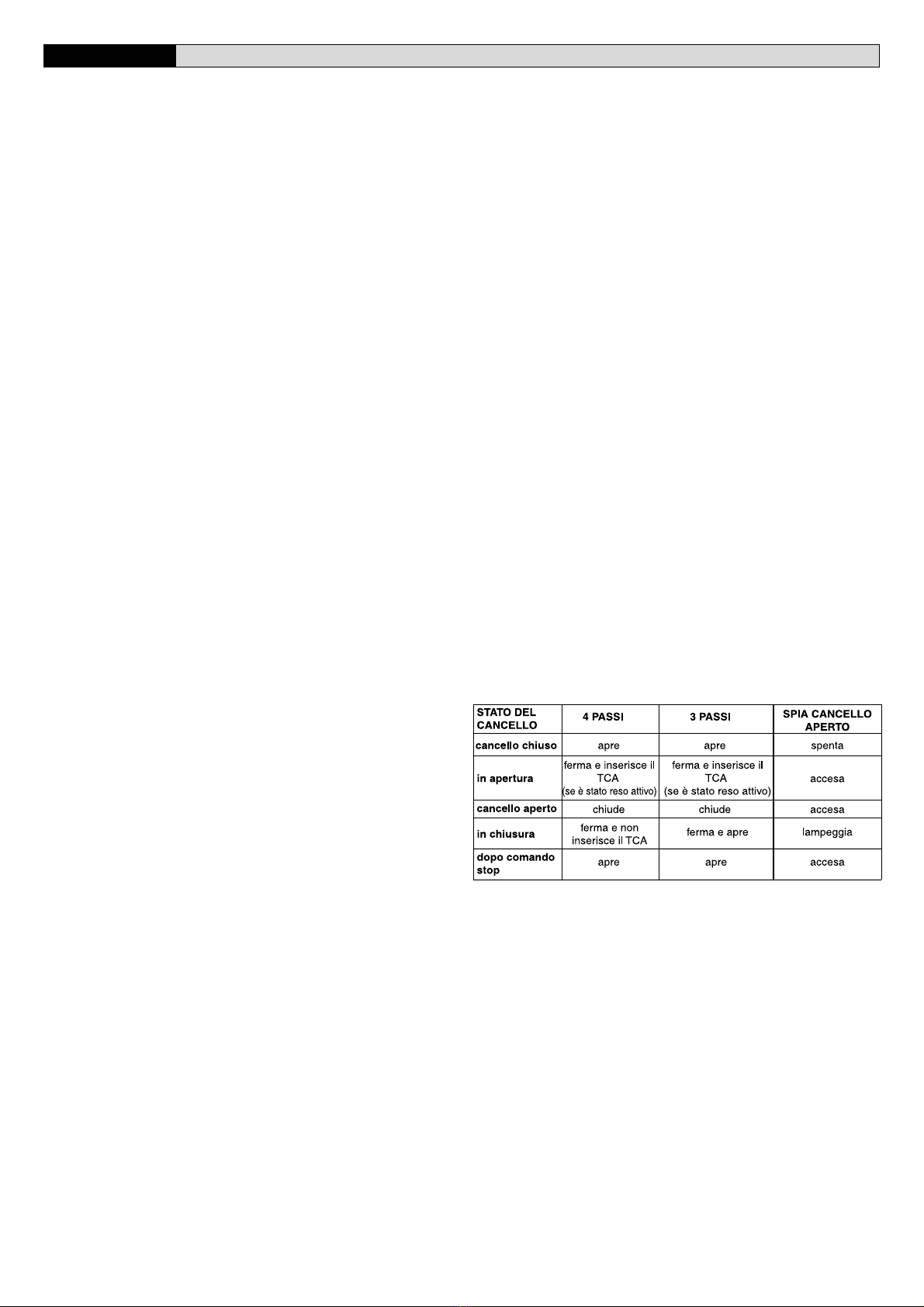
3.2) Quadro comando SCE/SCE-MA/SCE-MA S (Fig.16)
Alimentazione accessori: ........................................24Va.c. (180mA max)
24Va.c. Vsafe SCE-MA (180mA max)
Regolazione limitatore di coppia: .......................... In chiusura e apertura
Tempo di chiusura automatica: .............................................. Da 2 a 120s
Collegamento lampeggiante: ........................................ 24Va.c. max 25W
Tempo di accensione lampada di servizio:......................................... 90s
Radioricevente Rolling-Code incorporata: ........... Frequenza 433.92 MHz
Codifica: ................................................ Algoritmo Rolling-Code Clonabile
N°combinazioni: ........................................................................ 4 miliardi
Impedenza antenna:......................................................... 50Ohm (RG58)
N°max radiocomandi memorizzabili: ................................................... 63
Spazio rallentamento:....... chiusura: ~23 cm ............... apertura: ~15 cm
4) INSTALLAZIONE DELL’ATTUATORE
4.1) Verifiche preliminari:
•Controllare il bilanciamento della porta.
•Controllare lo scorrimento della porta per tutta la corsa.
•Se la porta non èdi nuova installazione, controllare lo stato di usura di
tutti i componenti.
•Sistemare o sostituire le parti difettose o usurate.
•L’affidabilitàe la sicurezza dell’automazione èdirettamente influenzata
dallo stato della struttura della porta.
4.2) Montaggio
Tolto l’imballo ricordiamo di smaltire tutti i componenti dell’imballo separan-
do i diversi tipi di materiale (cartone, polistirolo, pvc ecc.) secondo quanto
previsto dalle norme nazionali vigenti.
•Togliere dalla cremonese della porta, il catenaccio di blocco esistente.
•Posizionare il giunto “G”come in fig.6.
•Posizionare il mezzo binario come in fig.7 ed abbassare fino al piano

10 -
EOS - Ver. 07
D811325_07
MANUALE PER L’INSTALLAZIONEITALIANO
di appoggio mettendo in tensione la catena/cinghia ed ottenendo così
il binario intero.
•Posizionare il giunto ripartito a metàfra i due semibinari come in fig.8.
•Bloccare il giunto avvitando le apposite viti in dotazione come in fig.9.
L’apriporta ècosìpronto per la posa in opera.
•Segnare la mezzeria della porta e fissare il giunto snodabile del binario
al telaio della porta come in fig.10. Se l’altezza del soffitto dell’ambiente
lo consente, èpossibile montare il giunto snodato piùin alto fissandolo
all’architrave in muratura con tasselli.
•Con l’aiuto di un appoggio adeguato, alzare la testa motorizzata fino a
livellare il binario come in fig.11.
•Fissare le due staffe di supporto al soffitto come in fig.12. Ricontrollare
il tutto e fissare le due staffe di supporto sulla piastra base del motori-
duttore.
•Sbloccare il carrello di traino (fig.13) tirando il cordino e portare il braccio
di traino fino al telo della porta. Fissare il braccio di traino al telo della
porta come in fig.14 usando le viti in dotazione.
•Applicare gli adesivi forniti in prossimitàdei punti pericolosi (Fig.5).
5) PREDISPOSIZIONE IMPIANTO ELETTRICO (Fig.15)
I) Interruttore onnipolare omologato con apertura contati di almeno
3mm provvisto di protezione contro i sovraccarichi ed i corto circuiti,
atto a sezionare l’automazione dalla rete.
Installare a monte dell’automazione, se non giàpresente,un interrut-
tore onnipolare omologato con soglia 0,03.
Qr) Quadro comando e ricevente incorporata.
M) Attuatore
Ft) Fotocellula trasmittente
Fr) Fotocellule ricevente
T) Trasmittente 1-2-4 canali
Predisporre l’arrivo dei collegamenti degli accessori, dei dispositivi di
sicurezza e di comando al gruppo motore tenendo nettamente separati i
collegamenti a tensione di rete dai collegamenti in bassisima tensione di
sicurezza (24V), utilizzando l’apposito passacavo (fig.14 rif.P1). Procedere
al loro collegamento come indicato nello schema elettrico.
I cavi di connessione accessori devono essere protetti da canaletta (fig.14
rif.C1).
5.1) Collegamenti morsettiera (Fig.16)
AVVERTENZE - Nelle operazioni di cablaggio ed installazione riferirsi
alle norme vigenti e comunque ai principi di buona tecnica.
I conduttori alimentati a bassisima tensione di sicurezza (24V), devono
essere fisicamente separati dai conduttori a bassa tensione, oppure
devono essere adeguatamente isolati con isolamento supplementare di
almeno 1mm.
I conduttori devono essere vincolati da un fissaggio supplementare in
prossimitàdei morsetti, per esempio mediante fascette.
ATTENZIONE! Per il collegamento alla rete, utilizzare cavo multipolare
di sezione minima 3x1.5mm2e del tipo previsto dalle normative
vigenti. A titolo di esempio, se il cavo è all’esterno (all’aperto), deve
essere almeno pari a H07RN-F mentre, se all’interno (in canaletta),
deve essere almeno pari a H05 VV-F con sezione 3x1.5mm2.
JP1
1 Ingresso trasformatore 0 Va.c.
2 Ingresso trasformatore 15 Va.c.
3 Ingresso trasformatore 24 Va.c.
JP14 (Disponibile solo nelle schede SCE-MA S.)
4 Uscita seriale TX1
5 Uscita seriale TX2
6 Ingresso seriale RX1
7 Ingresso seriale RX2
JP5
8-9 Ingresso riferimento posizione
10-11 Ingresso Pulsante START (N.O.).
10-12 Ingresso Pulsante STOP (N.C.). Se non si utilizza lasciare il
ponticello inserito.
10-13 Ingresso Fotocellula (N.C.).
10-14 Ingresso Fault (N.O.).Ingresso per fotocellule dotate di contatto
N.O. di verifica (Fig.16) .Disponibile solo nelle schede SCE-MA e
SCE-MA S.
JP6
15-16 Collegamento motore:
15 motore + (grigio)
16 motore - (marrone)
17-18 Uscita 24Va.c. per luce lampeggiante (25W max)
19-20 Uscita 24Va.c. 180mA max - alimentazione fotocellule o altri
dispositivi.
21-22 Uscita 24Va.c. Vsafe 180mA max - alimentazione trasmettitori
fotocellule con verifica. Disponibile solo nelle schede SCE-MA e
SCE-MA S.
23-24 Uscita (Contatto N.O. (24Va.c./0.5A max)) per spia cancello
aperto o in alternativa 2°canale radio (vedi paragrafo “configura-
zione”)
25-26 Ingresso antenna per scheda radioricevente integrata (25 segna-
le - 26 calza).
N.B. La scheda di controllo viene fornita con una serie di ponti precablati
per facilitare l’installatore in opera.
I ponti riguardano i morsetti: 10-12, 10-13. Se i morsetti sopraindicati,
vengono utilizzati, togliere i rispettivi ponti.
6) PARAMETRI DI CONTROLLO MOVIMENTO MOTORI
I parametri funzionali possono essere variati mediante il programmatore a
display incorporato o mediante UNIPRO. Di seguito viene spiegato il
significato di ciascuna opzione e poi viene indicato il procedimento per
l’impostazione.
Significato delle impostazioni:
- Tempo Chiusura Automatica: regola il tempo di pausa a porta aperta, a
seguito del quale si ha la richiusura automatica se èattiva la funzione
TCA.
- Coppia (forza di spinta) motori: regola la forza di spinta applicata
elettronicamente al motore durante le manovra di apertura e chiusura.
ATTENZIONE: Verificare che il valore della forza d’impatto
misurato nei punti previsti dalla norma EN12445, sia inferiore
a quanto indicato nella norma EN 12453.
Una errata impostazione della coppia può creare danni a perso
ne, animali o cose.
- Logica di funzionamento a 3 Passi 4 Passi: il comando di start, a
seconda che sia attiva la logica a 3 passi oppure quella a 4 passi,
modifica lo stato del cancello come indicato nella tabella sotto.
Viene anche indicato lo stato della spia cancello aperto.
- Blocca Impulsi: attiva l’inibizione del comando di start da pulsante e start
da radiocomando durante l’apertura della porta.
- Fotocellule in apertura: Se reso attivo inibisce le fotocellule durante
l’apertura. In questo caso l’intervento delle fotocellule durante l’apertura
viene ignorato. L’intervento delle fotocellule durante la chiusura provo-
ca l’arresto della porta e la riapertura. Se èreso non attivo, l’intervento
della fotocellula in apertura provoca l’arresto della porta e la riapertura
una volta che l’ostacolo sia stato rimosso.
- Spia cancello aperto o II°canale radio: se attiva consente di collegare
una luce spia a 24Va.c. come in figura 16. In questo caso la luce indica
la posizione del cancello come specificato nella tabella sopra. Se non
attiva, l’uscita ai morsetti 23-24 presenta un contatto libero da tensione
e normalmente aperto, che viene attivato solo per 1 secondo ad ogni
pressione del tasto 2 del radiocomando associato. Il tasto 1 èriservato
per il comando di start.
- Fotocellule non verificate: se reso attivo inibisce la funzione di verifica
delle fotocellule, consentendo la connnessione di dispositivi non dotati
di contatto supplementare verifica.
7) PROGRAMMAZIONE
7.1) Programmazione mediante display
Il programmatore a display presente nella scheda consente di impostare
tutte le funzioni del quadro comandi SCE.

EOS- Ver. 07
- 11
D811325_07
MANUALE PER L’INSTALLAZIONE ITALIANO
Fare riferimento alle Fig. A e B.
Il parametro predefinito, èquello chiuso fra parentesi quadre [0]
Tra parentesi rotonde viene indicata la scritta che appare sul display.
Premere il tastino OK, si ottiene un menùdi presentazione, premere due
volte ok per by-passare questa presentazione.
Si entra ora in un menùcomposto dai seguenti sottomenù: Parametri,
logiche, radio, lingua, default, autosettaggio ed autodiagnosi. Nei primi 4
menùèpossibile spostarsi con i tasti su/giùall’interno del menùed entrare
nei sottomenù, confermando i valori impostabili con il tasto ok.
Nel menùDEFAULT èpossibile, premendo ok, riprogrammare la centrale
con i valori di fabbrica. Nel menùAUTODIAGNOSI èpossibile fare un
controllo dei collegamenti esterni.
Per ritornare indietro ed uscire dalla programmazione premere contempo-
raneamente i tasti su/giùpiùvolte.
Se a fine diagnosi la risposta èOK, la centralina e i dispositivi ad essa
collegati funzionano correttamente.
Nota: Il tasto “+” (freccia su) a display spento (non in programmazio-
ne) svolge la funzione di START.
7.2) Programmazione mediante UNIPRO
Collegare il programmatore UNIPRO alla centralina tramite l’accessorio
UNIDA (Vedere fig.27). La centrale SCE non alimenta il programmatore
UNIPRO che quindi necessita di apposito alimentatore.
Menu Parametri
- Tempo Chiusura Automatica (TCA) [10s]
Impostare numericamente il valore del tempo di chiusura automatica da
2 a 120 secondi.
- Coppia motori apertura (Coppia ap) [ 50% ]
Impostare numericamente il valore di coppia dei motori tra 1% e 99%.
- Coppia motori chiusura (Coppia ch) [ 50% ]
Impostare numericamente il valore di coppia dei motori tra 1% e 99%.
- Zona (Zone) [ 0 ] (Disponibile solo per e SCE-MA S.)
(UNIPRO
⇒
Parametri avanzati
⇒
indirizzo 1)
Impostare il numero di zona tra un valore minimo di 0 ed un valore
massimo di 127. Vedi paragrafo “Connessione seriale”.
Menu Logiche
- TCA (TCA) [ OFF ]
ON Attiva la chiusura automatica
OFF Esclude la chiusura automatica.
- 4Passi o 3 Passi (3 Passi) [ OFF ]
ON Abilita la logica 3 passi.
OFF Abilita logica 4 passi.
- Blocca Impulsi (Bl iMP) [ OFF ]
ON Abilita blocca impulsi in apertura.
OFF Esclude blocca impulsi in apertura.
- Fotocellule in apertura (Phot Ap) [ OFF ]
ON: Attiva solo in chiusura.
OFF: Attiva sia in apertura che in chiusura.
- Test fotocellule (test phot) [ OFF ]
(UNIPRO
⇒
Logiche avanzate
⇒
indirizzo 15)
(Disponibile solo nelle schede SCE-MA e SCE-MA S.)
ON Attiva la verifica delle fotocellule
OFF Disattiva la verifica delle fotocellule
- Spia cancello aperto o II°canale radio (sca 2ch) [ OFF ]
ON Attiva l’uscita rele in modalitàSpia cancello aperto.
OFF Attiva l’uscita relècome II°canale radio
- Programmazione radiocomandi (prog radio) [ OFF ]
(UNIPRO
⇒
Logiche avanzate
⇒
indirizzo 15)
ON Abilita la memorizzazione via radio dei trasmettitori:
1- Premere in sequenza il tasto nascosto (P1) e il tasto normale (T1-
T2-T3-T4) di un trasmettitore giàmemorizzato in modalitàstandard
attraverso il menu radio.
2- Premere entro 10s il tasto nascosto (P1) ed il tasto normale (T1-
T2-T3-T4) di un trasmettitore da memorizzare.
La ricevente esce dalla modalitàprogrammazione dopo 10s, entro
questo tempo èpossibile inserire ulteriori nuovi trasmettitori.
Questa modalitànon richiede l’accesso al quadro comando.
OFF Disabilita la memorizzazione via radio dei trasmettitori.
Itrasmettitori vengono memorizzatisoloutilizzando l’appositomenuRadio.
- Codice Fisso (cod fisso) [ OFF ]
(UNIPRO
⇒
Logiche avanzate
⇒
indirizzo 13)
ON Il ricevitore risulta configurato per il funzionamento in modalità
codice fisso, vedi paragrafo “Clonazione dei Radiotrasmettitori”
OFF Il ricevitore risulta configurato per il funzionamento in modalità
rolling-code, vedi paragrafo “Clonazione dei Radiotrasmettitori”
- Pre allarme (pre All) [ OFF ]
ON Il lampeggiante si accende circa 3 secondi prima della partenza del
motore
OFF Il lampeggiante si accende contemporaneamente alla partenza del
motore
- Loop (LOOP) [ OFF ] (Disponibile solo nelle schede SCE-MA S.)
(UNIPRO
⇒
Logiche avanzate
⇒
indirizzo 11)
ON Nel caso di collegamento centralizzato chiuso ad anello (Fig.26),
settare la centrale su ON.
OFF Nel caso di collegamento centralizzato aperto (Fig.26) settare la
centrale su OFF.
- Master/Slave (master) [ OFF ]
(Disponibile solo nelle schede SCE-MA S.)
(UNIPRO
⇒
Logiche avanzate
⇒
indirizzo 12)
ON Il quadro comando viene settato come Master in un collegamento
centralizzato (vedi paragrafo “Connessione seriale centralizzata”).
OFF Il quadro comando viene settato come Slave in un collegamento
centralizzato (vedi paragrafo “Connessione seriale centralizzata”).
8) DATI TECNICI RICEVITORE INTEGRATO
Canali di uscita della ricevente:
- canale uscita1, se reso attivo comanda uno START
- canale uscita 2, se reso attivo comanda l’eccitazione del relèII°canale
radio per 1s.
Versioni trasmettitori utilizzabili:
Tutti i trasmettitori ROLLING CODE compatibili con
INSTALLAZIONE ANTENNA
Usare una antenna accordata sui 433MHz.
Per il collegamento Antenna-Ricevitore usare cavo coassiale RG58.
La presenza di masse metalliche a ridosso dell’antenna, puòdisturbare la
ricezione radio. In caso di scarsa portata del trasmettitore, spostare
l’antenna in un punto piùidoneo.
9) CONFIGURAZIONE RICEVITORE
Il ricevitore a bordo di tipo clonabile unisce le caratteristiche di estrema
sicurezza alla copiatura della codifica a codice variabile (rolling code), la
praticitàdi poter effettuare, grazie ad un esclusivo sistema, operazioni di
“clonazione”di trasmettitori.
Clonare un trasmettitore significa generare un trasmettitore in grado di
inserirsi automaticamente nella lista dei trasmettitori memorizzati nel
ricevitore aggiungendosi o sostituendo un particolare trasmettitore.
La clonazione per sostituizione consente di creare un nuovo trasmettitore
che prende il posto nel ricevitore di un trasmettitore precedentemente
memorizzato, in quemodo sto saràpossibile rimuovere dalla memoria e
rendere non piùutilizzabile un trasmettitore.
Saràquindi possibile programmare a distanza e senza intervenire sul
ricevitore un gran numero di trasmettitori in aggiunta o in sostituzione di
trasmettitori che, per esempio, siano stati smarriti.
Quando la sicurezza della codifica non sia determinante, il ricevitore a
bordo permette di effettuare la clonazione in aggiunta a codice fisso che,
rinunciando al codice variabile, permette comunque di avere una codifica
con un elevato numero di combinazioni, mantenendo la possibilitàdi
“copiare”un qualsiasi trasmetittore giàprogrammato.
PROGRAMMAZIONE
La memorizzazione dei trasmettitori puòavvenire in modalitàmanuale o a
mezzo del programmatore UNIRADIO, che consente la gestione tramite il
software EEdbase del database completo dell’installazione.
In questo ultimo caso la programmazione della ricevente avviene tramite
la connessione di UNIRADIO al quadro comando SCE, utilizzando gli
accessori UNIFLAT e UNIDA come indicato in Fig. 27.
10) PROGRAMMAZIONE MANUALE
Nel caso di installazioni standard nelle quali non siano richieste le funzio-
nalitàavanzate èpossibile procedere alla memorizzazione manuale dei
trasmettitori, facendo riferimento alla Fig.B per la programmazione base.
- Se si desidera che il trasmettitore attivi l’uscita1 (START) con il tasto1
o con il tasto 2 o con il tasto 3 o con il tasto 4, inserire il trasmettitore nel
menu tasto start come in fig. B.
- Se si desidera che il trasmettitore attivi l’uscita2 (rele II°canale radio)
con il tasto1 o con il tasto 2 o con il tasto 3 o con il tasto 4, inserire il
trasmettitore nel menu tasto 2can. come in fig. B.
Nota: Il tasto nascosto P1 assume aspetto diverso a seconda del modello
di trasmettitore.

12 -
EOS - Ver. 07
D811325_07
MANUALE PER L’INSTALLAZIONEITALIANO
Per i trasmettitori dotati di tasto nascosto, premere il pulsante nascosto
P1 (Fig.B1). Per i trasmettitori sprovvisti del tasto nascosto, il tasto P1
corrisponde alla pressione contemporanea dei 4 tasti del trasmettitore o,
aprendo il vano batteria, a ponticellare con un cacciavite le due piazzole
P1 (Fig.B2).
NOTA IMPORTANTE: CONTRASSEGNARE IL PRIMO TRASMETTITO-
RE MEMORIZZATO CON IL BOLLINO CHIAVE (MASTER).
Il primo trasmettitore, nel caso di programmazione manuale, assegna il
CODICE CHIAVE DEL RICEVITORE; questo codice risulta necessario per
poter effettuare la successiva clonazione dei radiotrasmettitori.
11) CLONAZIONE DEI RADIOTRASMETTITORI
Clonazione con rolling code/Clonazione a codice fisso
Fate rifermento alle istruzioni UNIRADIO e alla Guida programmazione
CLONIX
11.1) PROGRAMMAZIONE AVANZATA: COMUNITÀ DI RICEVITORI
Fate rifermento alle istruzioni UNIRADIO e alla Guida programmazione
CLONIX
12) CONNESSIONE SERIALE CENTRALIZZATA (disponibile solo per
SCE-MA S)
Il quadro di comando SCE-MA S consente, tramite appositi ingressi e
uscite seriali, la connessione centralizzata di piùautomazioni. In questo
modo èpossibile, con un unico comando, eseguire l’apertura o la chiusura
di tutte le automazioni connesse.
Seguendo lo schema di Fig. 26, procedere alla connessione di tutti i quadri
comando, utilizzando esclusivamente un doppino di tipo telefonico.
Nel caso si utilizzi un cavo telefonico con piùcoppie risulta indispensabile
utilizzare i fili della stessa coppia.
La lunghezza del cavo telefonico fra una apparecchiatura e la succes-
siva non deve eccedere i 250 m.
A questo punto ènecessario configurare opportunamente ogni quadro
comando, impostando inanzitutto una centrale MASTER, che avràil
controllo di tutte le altre, necessariamente settate come SLAVE (vedi menu
logiche).
Impostare inoltre il numero di Zona (vedi menu parametri) tra 0 e 127.
Il numero di zona consente di creare dei gruppi di automazioni, ognuna
delle quali risponde al Master di Zona. Ogni zona può avere un solo
Master, il Master della zona 0 controlla anche gli Slave delle altre zone.
La chiusura ad anello della connessione seriale (indicata con un tratteggio
in Fig.27), ènecessaria solamente se si desidera, tramite UNIPRO,
verificare il numero dei dispositivi collegati.
12.1) Programmazione impianto centralizzato attraverso display
Il programmatore a display presente nella scheda consente di impostare
tutte le funzioni del quadro comandi SCE. Fare riferimento alle Fig. A e B.
Nel menùPARAM. impostare il numero di zona, nel menùLogiche
impostare i settaggi di anello chiuso/anello aperto e di master/slave.
12.2) Programmazione impianto centralizzato attraverso UNIPRO
Collegare il programmatore UNIPRO alla centralina tramite l’accessorio
UNIDA (Vedere Fig.27).
Fare riferimento alle Istruzioni UNIPRO per ulteriori informazioni.
13) DIAGNOSTICA E MONITORAGGIO
Il display presente sul quadro SCE sia nel normale funzionamento, sia nel
caso di anomalie visualizza alcune utili informazioni.
Diagnostica:
Nel caso di malfunzionamenti il display visualizza un messaggio che indica
quale dispositivo ènecessario verificare:
STRT = attivazione ingresso START
STOP = attivazione ingresso STOP
PHOT = attivazione ingresso PHOT
FLT = attivazione ingresso FAULT fotocellule verificate (solo SCE-MA
e SCE-MA S
Nel caso l’anta incontri un’ostacolo, il quadro SCE ferma e comanda
un’inversione, simultaneamente il display visualizza il messaggio “AMP”.
Monitoraggio:
Nelle fasi di apertura e chiusura il display visualizza quattro cifre separate
da un punto, ad es.
35.6 .
Le prime due cifre si aggiornano costantemente
durante la manovra e rappresentano la coppia massima raggiunta.
Le ultime due cifre rappresentano il valore di coppia impostato nel menu
parametri. Questi valori consentono di correggere l’impostazione della
coppia.
Se il valore di coppia massimo raggiunto durante la manovra si avvicina
sensibilimente al valore impostato, potrebbero verificarsi in futuro anomalie
di funzionamento dovute all’usura o a piccole deformazioni dell’anta.
Si consiglia pertanto di verificare la coppia massima raggiunta (le prime due
cifre), durante alcune manovre in fase di installazione ed eventulmente
impostare nel menu parametri un valore superiore di circa 15/20 punti
percentuali.
14) STATISTICHE
Le statistiche sono gestite attraverso UNIPRO.
Oltre alle statistiche standard sono disponibili le seguenti statistiche
avanzate:
- Numero esecutori di zona (statistiche avanzate) Indirizzo 16: indica
quanti sono gli attuatori appartenenti alla medesima zona del master
(viene aggiornato solo nelle schede master).
- Numeroesecutoritotali(statisticheavanzate)Indirizzo 17: indica quanti sono
in totale gli attuatori collegati (viene aggiornato solo nelle schede master)
Fare riferimento alle Istruzioni UNIPRO per ulteriori informazioni.
15) REGOLAZIONE TENDICATENA (EOS)
L’automazione viene fornita giàtarata e collaudata. Nel caso necessiti
aggiustare la tensione della catena agire come indicato in fig.17.
ATTENZIONE: La molla antistrappo non deve mai essere completa-
mente compressa. Verificare scrupolosamente che la molla non vada
in totale compressione durante il funzionamento.
15.1) TENSIONAMENTO DELLA CINGHIA (EOS-C)
L’automazione viene fornita giàtarata e collaudata. Nel caso necessiti
aggiustare la tensione della cinghia agire come indicato in Fig. 17A.
16) MENU REGOLAZIONE FINECORSA
Il quadro comando SCE dispone di un menu di regolazione dei finecorsa di
apertura e chiusura che semplifica la procedura di installazione.
Facendo riferimento alle Fig.18/19 e alla Fig.B di programmazione del
quadro comando procedere come segue:
•Dare avvio ad una operazione di regolazione finecorsa portandosi
nell’apposito menu del quadro SCE (Fig.B).
•Alla visualizzazione del messaggio “CLOSE”, portare l’anta nella posi-
zione di chiusura desiderata utilizzando i pulsanti “+”e “-”della centrale,
tenendo presente che il pulsante “-”chiude l’anta, mentre il pulsante “+”
apre l’anta.
Appena l’anta si trova nella posizione di chiusura desiderata premere il
pulsante “OK”in modo da memorizzare la posizione di finecorsa
chiusura.
•Alla visualizzazione del messaggio “OPEN”, portare l’anta nella posizio-
ne di apertura desiderata utilizzando i pulsanti “+”e “-”della centrale.
Appena l’anta si trova nella posizione di apertura desiderata premere il
pulsante “OK”in modo da memorizzare la posizione di finecorsa
apertura.
NOTA: Queste manovre vengono eseguite in modalità “uomo
presente” a velocità ridotta e senza l’intervento delle sicurezze.
•Il quadro comanda ora una manovra di chiusura parziale in modo da
permettereil posizionamento della camma di riferimento, e visualizzando
il messaggio “REF”si porta in modalitàdi attesa.
La camma va posizionata (Fig.19) ad una disanza di circa 230 mm dalla
base di fissaggio. La misura puòavere una variazione di circa ±13 mm
dovuto al passo della catena/cinghia.
Attenzione!! La camma va posizionata come indicato nel particolare 9A
e 9B della fig. 19. Un’errato posizionamento della camma può
provocare danni all’automazione.
•Dopo aver posizionato la camma premere il pulsante “OK”, il quadro
comanda la riapertura dell’anta per memorizzare la posizione della
camma di riferimento encoder.
•La regolazione dei finecorsa risulta cosìcompletata, portare l’anta in
chiusura e procedere ora ad una operazione di autosettaggio per
completare la messa a punto dell’automazione.
17) MENU AUTOSETTAGGIO
•Portare l’anta in posizione di chiusura
•Dare avvio ad una operazione di autosettaggio portandosi nell’apposito
menu del quadro SCE (Fig.B).
•Non appena premuto il pulsante OK viene visualizzato il messaggio “....
.... ....”, la centrale comanda una manovra di apertura seguita da una
manovra di chiusura, durante al quale viene automaticamente settato il
valore minimo di coppia necessario al movimento dell’anta.
Durante questa fase èimportanteevitare l’oscuramento delle fotocellule,
nonchèl’utilizzo dei comandi START, STOP e del display.
Al termine di questa operazione la centrale di comando avràautomati-
camente impostato i valori ottimali di coppia. Verificarli ed eventualmen-
te modificarli come descritto in programmazione.

EOS- Ver. 07
- 13
D811325_07
MANUALE PER L’INSTALLAZIONE ITALIANO
ATTENZIONE: Verificare che il valore della forza d’impatto
misurato nei punti previsti dalla norma EN12445, sia inferiore
a quanto indicato nella norma EN 12453.
Attenzione!! Durante l’autosettaggio la funzione di rileva
mento ostacoli non è attiva, l’installatore deve controllare il
movimento dell’automazione ed impedire a persone o cose di avvici-
narsi o sostare nel raggio di azione dell’automazione.
18) VELOCITÀ E COPPIA DI RALLENTAMENTO
N.B.: Nel caso la spinta, nella fase finale di apertura e chiusura non
consenta di ottenere la manovra completa desiderata, èpossibile aumen-
tare la forza del motoriduttore spostando il collegamento del trasformatore
dal morsetto 15V al morsetto 20V come in fig.20.
19) MANOVRA DI EMERGENZA
Nel caso manchi l’energia elettrica o, di avaria del sistema, per eseguire la
manovra manualmente, bisogna tirare il cordino collegato al carrello come
in fig.21. Per autorimesse prive di uscita secondaria èobbligatorio montare
un dispositivo di sblocco dall’esterno con chiave tipo il Mod.SM1 (fig.22) o
il Mod.SET/S (fig23).
20) VERIFICA DELL’AUTOMAZIONE
Prima di rendere definitivamente operativa l’automazione, controlla
re scrupolosamente quanto segue:
•Controllare il corretto funzionamento di tutti i dispositivi di sicurezza
(micro-finecorsa, fotocellule, coste sensibili ecc.)
•Verificare che la spinta (antischiacciamento) della porta sia entro i limiti
previsti dalle norme vigenti e comunque non troppo elevata rispetto alle
condizioni di installazione ed uso.
•Verificare che la molla tendicatena non si comprima completamente
durante la manovra.
•Verificare il comando di apertura manuale.
•Verificare l’operazione di apertura e chiusura con i dispositivi di coman-
do applicati.
•Verificare la logica elettronica di funzionamento normale e personaliz-
zata.
21) USO DELL’AUTOMAZIONE
Poichél’automazione puòessere comandata a distanza mediante
radiocomando o pulsante di start, e quindi non a vista, èindispensabile
controllare frequentemente la perfetta efficienza di tutti i dispositivi di
sicurezza. Per qualsiasi anomalia di funzionamento, intervenire rapida-
mente avvalendosi anche di personale qualificato. Si raccomanda di
tenereibambini a debita distanza dal raggio d’azione dell’automazione.
22) COMANDO
L’utilizzo dell’automazione consente l’apertura e la chiusura della porta in
modo motorizzato. Il comando puòessere di diverso tipo (manuale, con
radiocomando, controllo accessi con tessera magnetica ecc.) secondo le
necessitàe le caratteristiche dell’installazione. Per i vari sistemi di coman-
do, vedere le relative istruzioni. Gli utilizzatori dell’automazione devono
essere istruiti al comando e all’uso.
23) MANUTENZIONE
Per qualsiasi manutenzione, togliere alimentazione al sistema.
•Verificare periodicamente (2 volte l’anno) il tensionamento della catena/
cinghia.
•Eseguire saltuariamente la pulizia delle ottiche delle fotocellule
se installate.
•Far controllare da personale qualificato (installatore) la corretta
regolazione della frizione elettronica.
•Per qualsiasi anomalia di funzionamento, non risolta, togliere alimenta-
zione al sistema e richiedere l’intervento di personale qualificato (instal-
latore). Nel periodo di fuori servizio, attivare lo sblocco manuale per
consentire l’apertura e la chiusura manuale.
Se il cavo di alimentazione è danneggiato, esso deve essere
sostituito dal costruttore o dal suo servizio assistenza tecnica
o comunque da persona con qualifica similare, in modo da prevenire
ogni rischio.
24) ACCESSORI
SM1 Sblocco esterno da applicare alla cremonese esistente della
porta basculante (fig.22).
SET/S Sblocco esterno a maniglia rientrante per porte sezionali max.
50mm (fig.23).
APT Accessori prolunghe e staffe per montaggio distanziato o aderen-
te al soffitto (fig.24).
ST Sblocco automatico catenacci per porte basculanti a molle.
Applicato al braccetto di comando, sgancia automaticamente i
catenacci laterali della porta (fig.25).
25) DEMOLIZIONE
Attenzione: Avvalersi esclusivamente di personale qualificato.
L’eliminazione dei materiali va fatta rispettando le norme vigenti.
Nel caso di demolizione dell’automazione non esistono particolari pericoli
o rischi derivanti dall’automazione stessa.
Èopportuno, in caso di recupero dei materiali, che vengano separati per
tipologia (parti elettriche - rame - alluminio - plastica - ecc.).
26) SMANTELLAMENTO
Attenzione: Avvalersi esclusivamente di personale qualificato.
Nel caso l’automazione venga smontata per essere poi rimontata in altro
sito bisogna:
•Togliere l’alimentazione e scollegare tutto l’impianto elettrico esterno.
•Nel caso alcuni componenti non possano essere rimossi o risultino
danneggiati, provvedere alla loro sostituzione.
Le descrizioni e le illustrazioni del presente manuale non sono
impegnative. Lasciando inalterate le caratteristiche essenziali del
prodotto, la Ditta si riserva di apportare in qualunque momento le
modifiche che essa ritiene convenienti per migliorare tecnicamente,
costruttivamente e commercialmente il prodotto, senza impegnarsi
ad aggiornare la presente pubblicazione.

14 -
EOS - Ver. 07
D811325_07

EOS- Ver. 07
- 15
D811325_07

16 -
EOS - Ver. 07
D811325_07
INSTALLATION MANUALENGLISH
Thank you for buying this product, our company is sure that you will be more
than satisfied with the product’s performance. The product is supplied with
a “Warnings”leaflet and an “Instruction booklet”. These should both be
readcarefullyastheyprovideimportantinformationaboutsafety,installation,
operation and maintenance. This product complies with the recognised
technical standards and safety regulations. We declare that this product is
in conformity with the following European Directives: 89/336/EEC and 73/
23/EEC, 98/37/EEC (and subsequent amendments).
1) GENERAL SAFETY
WARNING! An incorrect installation or improper use of the product
can cause damage to persons, animals or things.
•The “Warnings”leaflet and “Instruction booklet”supplied with this
product should be read carefully as they provide important information
about safety, installation, use and maintenance.
•Scrap packing materials (plastic, cardboard, polystyrene etc) according
to the provisions set out by current standards. Keep nylon or polystyrene
bags out of children’s reach.
•Keep the instructions together with the technical brochure for
future reference.
•This product was exclusively designed and manufactured for the use
specified in the present documentation. Any other use not specified in
this documentation could damage the product and be dangerous.
•The Company declines all responsibility for any consequences resulting
from improper use of the product, or use which is different from that
expected and specified in the present documentation.
•Do not install the product in explosive atmosphere.
•The construction components of this product must comply with the
following European Directives: 89/336/CEE, 73/23/EEC, 98/37/EEC
and subsequent amendments. As for all non EEC countries, the
abovementioned standards as well as the current national standards
should be respected in order to achieve a good safety level.
•The Company declines all responsibility for any consequences resulting
from failure to observe Good Technical Practice when constructing
closingstructures(door,gatesetc.),aswellas from any deformationwhich
might occur during use.
•The installation must comply with the provisions set out by the
followingEuropean Directives: 89/336/CEE, 73/23/EEC, 98/37/EEC and
subsequent amendments.
•Disconnect the electrical power supply before carrying out any work on
the installation. Also disconnect any buffer batteries, if fitted.
•Fit an omnipolar or magnetothermal switch on the mains power supply,
having a contact opening distance equal to or greater than 3,5 mm.
•Check that a differential switch with a 0.03A threshold is fitted just before
the power supply mains.
•Check that earthing is carried out correctly: connect all metal parts for
closure (doors, gates etc.) and all system components provided with an
earth terminal.
•Fit all the safety devices (photocells, electric edges etc.) which are
needed to protect the area from any danger caused by squashing,
conveying and shearing.
•Position at least one luminous signal indication device (blinker) where
it can be easily seen, and fix a Warning sign to the structure.
•The Company declines all responsibility with respect to the automation
safety and correct operation when other manufacturers’components
are used.
•Only use original parts for any maintenance or repair operation.
•Do not modify the automation components, unless explicitly authorised
by the company.
•Instruct the product user about the control systems provided and the
manual opening operation in case of emergency.
•Donotallowpersonsorchildren to remain in the automation operation area.
•Keep radio control or other control devices out of children’s reach, in
order to avoid unintentional automation activation.
•The user must avoid any attempt to carry out work or repair on
the automation system, and always request the assistance of
qualified personnel.
•Anything which is not expressly provided for in the present instructions,
is not allowed.
•Installation must be carried out using the safety devices and controls
prescribed by the EN 12978 Standard.
2) GENERAL OUTLINE
The EOS system is compatible with the EElink protocol for fast installation
and maintenance. It is suitable for motorising sectional doors (fig. 3),
protruding fully retracting spring-operated overhead doors (fig. 2) and
counterweight overhead doors provided with an appropriate towing arm
(fig. 4). The overhead door must not be higher than 2.5 metres. Its easy
installation allows fast fitting without needing the door to be modified. The
irreversible gearmotor keeps the door locked in the closing position.
The SCE control panel is supplied by the manufacturer with standard
setting. Any modification must be set by means of the incorporated display
programmer or by means of UNIPRO. The Control unit fully supports the
EELINK protocol.
These are its main characteristics:
- Control of a low-voltage motor up to 24 Vd.c.
- Electronic torque limiter with obstacle detection and torque self-learning
- Electronic limit switch with encoder
- Incorporated rolling-code radio receiver with transmitter cloning
- Presetting for operation by means of local and centralised commands
via wire (SCE-MA S).
The following optional accessories are available:
- CB EOS mod. buffer battery kit.
This allows the automation system to operate even when the mains power
supply is off for a short time.
NOTE: The buffer battery kit is to be installed on the actuator fixing base on
the ceiling side. A minimum distance of 50 mm must be kept between the
fixing base and the ceiling in the case where batteries are expected to be
installed at a later time.
3) TECHNICAL SPECIFICATIONS
3.1) Actuator
Power supply: .......................... 230Va.c. ±10%, 50/60Hz single-phase (*)
Motor voltage: ................................................................................. 24Vd.c.
Max. power absorbed from mains:....................................................180W
Lubrication: ................................................................... permanent grease
Towing and pushing force: ............................................................... 600N
Working stroke:..................... 2.60m (extension to 3.60m for PRE1 Mod.)
Average speed: ............................................................................. 5 m/min
Impact reaction: ........................ integrated torque limiter on control panel
Manoeuvres in 24 hours: ...................................................................... 100
Limit switch: ....................................................electronic with self-learning
Courtesy light:................................................ 24Va.c. 25W max, E14 bulb
Working temperature: ......................................................... -15°C / +60°C
Degree of protection: ......................................................................... IPX0
Total weight: ....................................................................................... 12kg
Noise level: ................................................................................ <70dB(A)
Dimensions: ................................................................................. see fig.1
(*) Available in all mains voltages.
3.2) SCE/SCE-MA/SCE-MA S Control panel (Fig.16)
Supply to accessories: ............................................ 24Va.c. (180mA max)
24Va.c. Vsafe SCE-MA (180mA max)
Torque limiter setting:.......................................... on closing and opening
Automatic closing time: .......................................................from 2 to 120s
Blinker connection: ........................................................ 24Va.c. max 25W
Service light switching-on time:........................................................... 90s
Incorporated rolling-code radio receiver: .............. frequency 433.92 MHz
Coding: ............................................... rolling-code algorithm to be cloned
No. combinations: ....................................................................... 4 milliard
Antenna impedance: ........................................................ 50Ohm (RG58)
Max no. radio controls to be memorised: ............................................. 63
Slow-down distance: ............closing: ~23 cm ............... opening: ~15 cm
4) ACTUATOR INSTALLATION
4.1) Preliminary checks
•Check that the door is balanced.
•Check that the door slides smoothly along its entire travel.
•If the door has not been newly installed, check the wear condition of all
its components.
•Repair or replace faulty or worn parts.
•The automation reliability and safety are directly influenced by the state
of the door structure.
4.2) Fitting
After unpacking, dispose of the parts which make up the package properly,
by separating the different type of materials (cardboard, polystyrene, PVC,
etc.) according to the national rules in force.
•Remove the existing locking bolt from the cremone bolt of the door.
•Position joint “G”as shown in fig.6.
•Position the half track as in fig. 7, and lower it onto the supporting surface
while tightening the chain/belt to obtain the whole track.
•Fit the joint to overlap each of the two half tracks by half its length, as
in fig.8.
•Secure the joint by tightening the appropriate screws supplied, as in fig.
9. The door opener is thus ready to be installed.

EOS- Ver. 07
- 17
D811325_07
INSTALLATION MANUAL ENGLISH
•Mark the mid-point of the door and fix the track articulated joint to the
door frame, as in fig.10. If the ceiling is high enough, the articulated
joint can be fitted higher up and fixed to the masonry lintel by means
of dowels.
•With the help of an adequate support, lift the motorised head until the
track is levelled, as in fig.11.
•Fix the two supporting brackets to the ceiling, as in fig.12. Recheck
everything and fix the two supporting brackets to the gearmotor base
plate.
•Release the towing carriage (fig.13) by pulling the wire, and bring the
towing arm as far as the door panel. Fix the towing arm to the door panel,
as in fig.14, using the screws supplied.
•Stick the adhesive labels supplied next to the dangerous points (Fig. 5).
5) ELECTRICAL INSTALLATION SET-UP (Fig.15)
I) Type-approved omnipolar circuit breaker with at least 3-mm contact
opening,providedwith protection against overloads and short circuits,
suitable for cutting out automation from the mains. Place, if not al
ready installed, a type-approved differential switch with a 0.03 A
threshold just before the automation system.
Qr) Control panel and incorporated receiver
M) Actuator
Ft) Transmitter photocell
Fr) Receiver photocells
T) 1-2-4 channel transmitter.
Arrange for the connections of accessories and safety and control devices
to reach the motor unit, keeping the mains voltage connections clearly
separate from the extra low safety voltage connections (24V) by means of
the appropriate cable holder (fig. 14 ref. P1).
Proceed to connection following the indications given in the wiring diagram.
The cables for connecting the accessories must be protected by a raceway
(fig. 14 ref. C1).
5.1) Terminal board connections (Fig.16)
WARNINGS - For wiring and installation operations, refer to the
current standards and good technical principles.
The wires supplied with extra low safety voltage (24V) must be kept
physically separate from the low voltage wires, or else they must be
provided with adequate additional insulation of at least 1mm.
The wires must be clamped by an extra fastener near the terminals, for
example by bands.
WARNING! For connection to the mains, use a multipolar cable with
a minimum of 3x1.5mm2cross section and complying with the
previously mentioned regulations. For example, if the cable is out side
(in the open), it has to be at least equal to H07RN-F, but if it is on the
inside (or outside but placed in a plastic cable cannel) it has to be or
at least egual to H05VV-F with section 3x1.5mm2.
JP1
1 Transformer input 0 Va.c.
2 Transformer input 15 Va.c.
3 Transformer input 24 Va.c.
JP14 (only available in the SCE-MA S boards)
4 TX1 serial output
5 TX2 serial output
6 RX1 serial input
7 RX2 serial input
JP5
8-9 Position reference input
10-11 START button input (N.O.).
10-12 STOP button input (N.C.). If not used, leave the jumper connected.
10-13 Photocell input (N.C.).
10-14 Fault input (N.O.). Input for photocells provided with N.O. checking
contact (Fig.16). Only available in the SCE-MA and SCE-MA S boards.
JP6
15-16 Motor connection:
15 motor + (grey)
16 motor - (brown)
17-18 24Va.c. output for blinking light (25W max)
19-20 24Va.c. 180mA max output –supply to photocells or other
devices
21-22 24Va.c.Vsafe180mAmaxoutput–supplytophotocelltransmitters
with check. Only available in the SCE-MA and SCE-MA S boards.
23-24 Output (N.O. contact (24Va.c./0.5A max)) for gate-open warning
light or alternatively 2nd radio channel (see “configuration”
paragraph)
25-26 Antenna output for integrated radio-receiver board (25 signal - 26
braid).
N.B. The control board is provided with a series of pre-wired jumpers to
make work easier for the installer.
The jumpers involve the following terminals: 10-12, 10-13. If the above-
mentioned terminals are used, remove their respective jumpers.
6) MOTOR MOVEMENT CONTROL PARAMETERS
The functional parameters can be changed by means of the incorporated
display programmer or the UNIPRO programmer.
Here is the explanation of the meaning of each option, followed by the
relevant setting procedure.
Meaning of the settings:
- Automatic Closing Time: regulates the dwell time with the door open,
following which the door is automatically closed if the TCA function is
active.
- Motor torque (pushing force): regulates the pushing force which is
electronically applied to the motor during the opening and closing
manoeuvres.
WARNING: Check that the impact force value measured at the
points established by the EN 12445 standard is lower than that
specified in the EN 12453 standard.
Incorrect sensitivity setting can cause injuries to persons or
animals, or damage to things.
- 3-step or 4-step function logic: the Start command modifies the gate
status depending on whether the 3-step or 4-step logic is active, as
specified in the table below. The status of the gate-open warning light
is also specified.
- Impulse lock: activates inhibition of the Start command from pushbutton
and Start command from radio-control device during gate opening.
- Photocells on opening: if activated, it inhibits the photocells during
opening. In this case, photocell triggering during opening is ignored.
Photocell triggering during closing causes the gate to stop and then
reopen. If not activated, photocell triggering on opening causes the gate
to stop and reopen once the obstacle has been removed.
- Gate-open or 2nd radio channel warning light: if activated, allows you to
connect a 24Va.c. warning light, as in figure 16. In this case the light
indicates the position of the gate as specified in the table above. If not
activated, the output to terminals 23 and 24 shows a current-free and
normally open contact, which is only activated for 1 second each time
key 2 is pressed on the associated radio-control device. Key 1 is
reserved for the Start command.
- Photocells not checked: if this setting is activated, it inhibits the photocell
checking function, allowing connection of devices not provided with
additional checking contact.
7) PROGRAMMING
7.1) Programming by means of the display
The display programmer available in the board allows you to set all the SCE
control panel functions.
Make reference to fig. A and B.
The predefined parameter is shown between square brackets [0].
The writing appearing on the display is indicated between round brackets.
Press the small OK key to display an introduction menu, press OK twice to
bypass this introduction. Now you enter a menu including the following
submenus: Parameters, logics, radio, language, default and self-diagnosis.
In the first 4 menus you can move up/down within each menu and enter the
submenus, then confirm the values set using the OK key.

18 -
EOS - Ver. 07
D811325_07
INSTALLATION MANUALENGLISH
If you press OK in the DEFAULT menu, you can reprogram the control unit
with the factory-set values. The SELF-DIAGNOSIS menu allows you to
check the external connections.
To go back and exit the programming function, simultaneously press the up/
down keys several times.
If, at the end of the diagnosis, the reply is OK, it means that the control unit
and connected devices work correctly.
Note: With the display off (not programming), the “+” (arrow up) key
carries out the START function.
7.2) Programming by means of UNIPRO
Connect the UNIPRO programmer to the control unit by means of the
UNIDA accessory (see fig. 27). The SCE control unit does not supply the
UNIPRO programmer, which therefore needs an appropriate supply unit.
Parameter Menu (PARAM)
-Automatic Closing Time (TCA) [10s]
Set the numerical value of the automatic closing time from 2 to 120
seconds.
-Opening motor torque (Op torque) [ 50% ]
Set the numerical value of the motor torque between 1% and 99%.
-Closing motor torque (Cls torque) [ 50% ]
Set the numerical value of the motor torque between 1% and 99%.
-Zone (Zone) [ 0 ] (Only available for SCE-MA S.)
(UNIPRO
⇒
Advanced parameters
⇒
address 1)
Set the zone number between a minimum value of 0 and a maximum
value of 127. See paragraph on “Serial connection”.
Logic Menu (logic.)
- TCA (TCA) [ OFF ]
ON Activates automatic closing
OFF Excludes automatic closing
- 3 Steps/4Step (3 step) [ OFF ]
ON Enables 3-step logic. stops and reopens
OFF Enables 4-step logic.
- Impulse lock (ibl open) [ OFF ]
ON Enables impulse lock during the opening phase.
OFF Excludes impulse lock during the opening phase.
- Photocells on opening (photc. open) [ OFF ]
ON Enables on closing phase only.
OFF: Enables on opening and closing phase.
- Photocell test (test phot) [ OFF ]
(UNIPRO
⇒
Advanced logics
⇒
address 14)
(Only available for SCE-MA and SCE-MA S)
ON Activates photocell check
OFF Deactivates photocell check
- Gate-open or 2nd radio channel warning light (sca 2ch) [ ON ]
ON The output between terminals 23 and 24s configured as Gate-open
warning light.
OFF The output between terminals 23and 24is configured as 2nd radio
channel.
- Radio transmitter programming (radio prog) [ OFF ]
(UNIPRO
⇒
Advanced logics
⇒
address 15)
ON This enables transmitter storage via radio:
1 –First press the hidden key (P1) and then the normal key (T1, T2,
T3 or T4) of a transmitter already memorised in standard mode by
means of the radio menu.
2 –Within 10s press the hidden key (P1) and the normal key (T1, T2,
T3 or T4) of a transmitter to be memorised.
The receiver exits the programming mode after 10s, other new
transmitters can be entered before the end of this time.
This mode does not require access to the control panel.
OFF This disables transmitter storage via radio.
The transmitters can only be memorised using the appropriate Radio
menu.
- Fixed Code (fixed code) [ OFF ]
(UNIPRO
⇒
Advanced logics
⇒
address 13)
ON The receiver is configured to operate in fixed code mode, see
paragraph on “Radio-transmitter cloning”.
OFF The receiver is configured to operate in rolling-code mode, see
paragraph on “Radio-transmitter cloning”.
-Prealarm (Pre AL) [ OFF ]
ON The blinker comes on about 3 seconds before the motors start
OFF The blinker comes on at the same time as the motors start
- Loop (loop) [ OFF ] (Only available for SCE-MA S)
(UNIPRO
⇒
Advanced logics
⇒
address 11)
ON In the case of a closed loop centralised connection (Fig.26), set the
control unit to ON.
OFF In the case of an open centralised connection (Fig.26), set the control
unit to OFF.
- Master/Slave (Master) [ OFF ] (Only available for SCE-MA S)
(UNIPRO
⇒
Advanced logics
⇒
address 12)
ON The control panel is set as Master in a centralised connection (see
Paragraph “CENTRALISED SERIAL CONNECTION”).
OFF The control panel is set as Slave in a centralised connection (see
Paragraph “CENTRALISED SERIAL CONNECTION”).
8) INTEGRATED RECEIVER TECHNICAL SPECIFICATION
Receiver output channels:
- output channel 1, if activated, controls a START command.
- output channel 2, if activated, controls the excitation of the 2nd radio
channel relay for 1s.
Transmitter versions which can be used:
all Rolling Code transmitters compatible with
ANTENNA INSTALLATION
Use an antenna tuned to 433MHz.
For Antenna-Receiver connection, use RG8 coaxial cable.
The presence of metallic masses next to the antenna can interfere with
radio reception. In case of insufficient transmitter range, move the antenna
to a more suitable position.
9) RECEIVER CONFIGURATION
The on-board receiver combines characteristics of utmost safety in copying
variable code (rolling code) coding with the convenience of carrying out
transmitter “cloning”operations thanks to an exclusive system.
Cloningatransmittermeans creating a transmitter which can be automatically
included within the list of the transmitters memorised in the receiver, either
as an addition or as a replacement of a particular transmitter.
Cloning by replacement is used to create a new transmitter which takes the
place of the one previously memorised in the receiver; in this way a specific
transmitter can be removed from the memory and will no longer be usable.
Therefore it will be possible to remotely program a large number of
additional transmitters or, for example, replacement transmitters for those
which have been lost, without making changes directly to the receiver.
When coding safety is not a decisive factor, the on-board receiver allows
you to carry out fixed-code additional cloning which, although abandoning
the variable code, provides a high number of coding combinations, therefore
keeping it possible to “copy”any transmitter which has already been
programmed .
PROGRAMMING
Transmitter storage can be carried out in manual mode or by means of the
UNIRADIO programmer which allows the complete installation database to
be managed through the Eedbase software.
In this second case, receiver programming takes place through the
connection of UNIRADIO to the SCE control panel, using the UNIFLAT and
UNIDA accessories as indicated in Fig. 27.
10) MANUAL PROGRAMMING
In the case of standard installations where advanced functions are not
required, you can proceed to manual storage of the transmitters, making
reference to fig. B for basic programming.
- If you wish the transmitter to activate output 1 (START) by means of
key1, key2, key3 or key4, enter the transmitter in menu “Start key”, as
in fig. B.
- If you wish the transmitter to activate output 2 (2nd radio channel relay)
by means of key1, key2, key3 or key4, enter the transmitter in menu “2nd
ch. key”, as in fig. B.
Note: Hidden key P1 appears differently depending on the transmitter model.
For transmitters with hidden key, press hidden key P1 (fig. B1). For
transmitters without hidden key, the key P1 function corresponds to
simultaneously pressing the 4 transmitter keys or, after opening the
battery compartment, bridging the two P1 points by means of a
screwdriver (fig. B2).
IMPORTANT NOTE: ATTACH THE ADH ESIVE KEY LABEL TO THE
FIRST MEMORISED TRANSMITTER (MASTER).
In the case of manual programming, the first transmitter assigns the key
code to the receiver; this code is necessary in order to carry out subsequent
cloning of the radio transmitters.

EOS- Ver. 07
- 19
D811325_07
INSTALLATION MANUAL ENGLISH
11) RADIO-TRANSMITTER CLONING
Rolling-code cloning / Fixed-code cloning
MakereferencetotheUNIRADIOInstructions and the CLONIX Programming
Guide.
11.1) ADVANCED PROGRAMMING: COLLECTIVE RECEIVERS
MakereferencetotheUNIRADIOInstructions and the CLONIX Programming
Guide.
12) CENTRALISED SERIAL CONNECTION (only available for SCE-MA S)
The SCE-MA S control panel allows several automation units to be
connected in a centralised way by means of appropriate serial inputs and
outputs. This makes it possible to use one single command to open and
close all the automation units connected.
Following the diagram in Fig. 27, proceed to connecting all the control
panels, exclusively using a telephone-type line.
Should a telephone cable with more than one pair be needed, it is
indispensable to use wires from the same pair.
The length of the telephone cable between one appliance and the next must
not exceed 250 m.
At this point, each of the control panels must be appropriately configured,
by setting a MASTER unit first of all, which will have control over all the
others, to be necessarily set as SLAVE (see logic menu).
Also set the Zone number (see parameter menu) between 0 and 127.
The zone number allows you to create groups of automation units,
each one answering to the Zone Master unit. Each zone can only be
assigned one Master unit, the Master unit in zone 0 also controls the Slave
units in the other zones.
Loop closing of the serial connection (indicated by a dotted line in Fig.26)
is only needed if you require to check the no. of the connected devices by
means of UNIPRO.
12.1) Programming of centralised installation through display
The display programmer available in the board is used to set all the SCE
control panel functions. Make reference to Fig. A and B. Set the zone
number from the PARAM. Menu, and set the closed-loop / open-loop and
master / slave values from the Logic menu.
12.2) Programming of centralised installation through Unipro
Connect the UNIPRO programmer to the control unit by means of the
UNIDA accessory (see fig.27).
Make reference to the UNIPRO Instructions for further information.
13) DIAGNOSTICS AND MONITORING
The display on the SCE panel shows some useful information, both during
normal operation and in the case of malfunctions.
Diagnostics:
In the case of malfunctions, the display shows a message indicating which
device needs to be checked:
STRT = START input activation
STOP= STOP input activation
PHOT= PHOT input activation
FLT = FAULT input activation for checked photocells (only SCE-MA and
SCE-MA S)
In the case where an obstacle is found, the SCE panel stops the door and
activates a reverse manoeuvre; at the same time the display shows the
“AMP”message.
Monitoring:
During the opening and closing phases, the display shows four digits
separated by a dot, for example 35.6 . The first two digits are constantly
updatedduringthemanoeuvre, and represent the maximum torque reached.
The last two digits represent the torque value set in the parameter menu.
These values allow the torque setting to be corrected.
If the maximum torque value reached during the manoeuvre gets sensibly
close to the value set, malfunctions may occur in the future following wear
or slight door deformation.
It is therefore advisable to check the maximum torque reached (the first two
digits) during some of the manoeuvres carried out in the course of
installation, and if necessary set a value about 15-20 percent points higher
in the parameter menu.
14) STATISTICS
he statistics are managed by the UNIPRO.
In addition to the standard statistics, the following advanced statistics are
available:
- Number of zone operating units (advanced statistics) Address 16:
indicates the number of actuators belonging to the same zone as that of
the master (only updated in the master boards).
- Number of total operating units (advanced statistics) Address 17:
indicates the number of actuators connected (only updated in the
master boards).
Make reference to the UNIPRO Instructions for further information.
15) CHAIN TIGHTENER ADJUSTMENT (EOS)
The operator supplied is already calibrated and inspected. Should the chain
tension need to be adjusted, proceed as shown in fig. 17.
WARNING: The anti-tear spring must never be completely compressed.
Scrupulously check that the spring does not become totally compressed
during operation.
15.1) BELT TENSIONING (EOS-C)
The automation is supplied already calibrated and duly tested. If the tension
of the belt needs to be adjusted, proceed as indicated in fig.17A.
16) LIMIT-SWITCH ADJUSTMENT MENU
The SCE control panel is provided with an adjustment menu for opening
and closing limit switches, which simplify the installation procedure.
Making reference to Fig. 18 and 19, and Fig. B showing control panel
programming, proceed as follows:
•Initiate a limit-switch adjustment operation by moving to the appropriate
SCE panel menu (Fig.B).
•When the “CLOSE”message is displayed, bring the door to the required
closing position using the “+”and “-”control unit buttons, keeping in mind
that the “-”button closes the door whereas the “+”button opens the door.
As soon as the door is in the required closing position, press the “OK”
button in order to memorise the closing limit-switch position.
•When the “OPEN”, message is displayed, bring the door to the required
opening position using the “+”and “-”control unit buttons. As soon as the
door is in the required opening position, press the “OK”button in order
to memorise the opening limit-switch position.
NOTE: These manoeuvres are carried out in “hold-to-run” mode at
reduced speed and without any safety device intervention.
•Now the control panel initiates a partial closing manoeuvre, in order to
allow the reference cam to be positioned, then displays the message
“REF”and moves to the wait mode.
The cam is to be positioned (Fig.19) at a distance of approximately 230
mm from the fixing base. This measurement can vary by approximately
±13 mm depending on the chain/belt pitch.
Warning!! The cam is to be positioned as shown in details 9A and 9B
of fig. 19. Any incorrect cam positioning can cause damage to the
operator.
•After positioning the cam, press the “OK”button, the control unit initiates
reopening the door to memorise the encoder reference cam positioning.
•At this point the limit-switch adjustment can be considered complete,
bring the door to its closing position and proceed to the autoset operation
to complete operator setting up.
17) AUTOSET MENU (Autoset)
•Bring the door to its closing position.
•Initiate an autoset operation by moving to the appropriate SCE panel
menu (Fig.B).
•As soon as the OK button is pressed, the following message will be
displayed “.... .... ....”, and the control unit initiates an opening manoeuvre
followed by a closing manoeuvre, during which the minimum torque
value needed for door movement will be automatically set.
During this phase, it is important to avoid obscuring the photocells, as
well as using the START and STOP commands and the display.
•By the end of this operation, the control unit will have automatically set
the optimum torque values. Check and, if necessary, modify them as
described in the programming section.
WARNING: Check that the impact force value measured at
the points established by the EN 12445 standard is lower than
that specified in the EN 12453 standard.
WARNING! During the autoset phase, the obstacle detection
function is not optimised; the installer must check the operator
movement and prevent persons and things from coming near or
stopping within the operating range.
18) SLOW-DOWN SPEED AND TORQUE
N.B.: In the case where, during the final opening and closing phases, the
pushing force does not allow the required manoeuvre to be completed, the
gearmotor force can be increased by moving the transformer connection
from terminal 15V to terminal 20V, as in fig.20.

20 -
EOS - Ver. 07
D811325_07
INSTALLATION MANUALENGLISH
19) EMERGENCY MANOEUVRE
In case of electric power failure or system malfunction, the manoeuvre must
be carried out manually by pulling the wire connected to the carriage, as in
fig.21. For garages which are not provided with a second exit, it is
compulsory to fit an external key release device like Mod. SM1 (fig.22) or
Mod. SET/S (fig.23).
20) AUTOMATION CHECK
Before the automation device finally becomes operational,
scrupulously check the following conditions:
•Check that all the safety devices (limit microswitches, photocells,
electric edges etc) operate correctly.
•Check that the door (antisquash) thrust is comprised within the limits set
out by the current standards, and anyway not too strong for the
installation and operating conditions.
•Check that the chain-tightener spring is not completely compressed
during manoeuvre.
•Check the manual opening control operation.
•Check the opening and closing operations using the control
devices fitted.
•Check the normal and customised operation electronic logics.
21) AUTOMATION DEVICE USE
Since the automation device can be remotely controlled by means of a radio
control device or a Start button, and therefore when not in sight, all the
safety devices must be frequently checked in order to ensure their perfect
efficiency. In the event of any malfunction, request immediate assistance
from qualified personnel. Children must be kept at a safe distance from the
automation operation area.
22) AUTOMATION CONTROL
The use of this control device allows the gate to be opened and closed
automatically. There are different types of controls (manual, radio control,
magnetic card access etc.) depending on the installation requirements and
characteristics.Forthevariouscontrolsystems,seetherelevant instructions.
Theautomation deviceusers mustbeinstructedoncontrol andoperation.
23) MAINTENANCE
Before carrying out any maintenance operation, disconnect the system
power supply.
•Periodically check the tension of the chain/belt (twice a year).
•Occasionally clean the photocell optical elements, if installed.
•Have a qualified technician (installer) check the correct setting of the
electronic clutch.
•When any operational malfunction if found, and not resolved,
disconnect the system power supply and request the assistance of a
qualified technician (installer). When the product is out of service,
activate the manual release device to allow the door to be opened
and closed manually.
If the power supply cable is damaged, it must be replaced
directly by our company or our technical service department or
by a technician having similar qualification so as to avoid any risks.
24) ACCESSORIES
SM1 External release device to be applied to the cremone bolt already
fitted to the overhead door (fig.22).
SET/S External release device with retracting handle for sectional doors
measuring max 50mm (fig.23).
APT Extension and bracket accessories used to fit the product away
from the door or close to the ceiling (fig.24).
ST Automatic bolt release device for spring-operated overhead doors. Fitted
to the control arm, it automatically releases the side door bolts (fig.25).
25) SCRAPPING
Warning!Thisoperationshould onlybecarriedoutbyqualifiedpersonnel.
Materials must be disposed of in conformity with the current regulations.
In case of scrapping, the automation devices do not entail any particular
risks or danger. In case of materials to be recycled, these should be sorted
out by type (electrical components, copper, aluminium, plastic etc.).
26) DISMANTLING
Warning! This operation should only be carried out by qualified personnel.
When the automation system is disassembled to be reassembled on
another site, proceed as follows:
•Disconnectthepowersupplyandthe entire external electrical installation.
•In the case where some of the components cannot be removed or are
damaged, they must be replaced.
The descriptions and illustrations contained in the present manual
arenotbinding.TheCompanyreserves the right to make any alterations
deemed appropriate for the technical, manufacturing and commercial
improvement of the product, while leaving the essential product
features unchanged, at any time and without undertaking to update
the present publication.
Other manuals for EOS
1
Table of contents
Languages:
Other BFT Door Opening System manuals

BFT
BFT VISTA SW 260 SXL User manual

BFT
BFT WIND RMB 130B 200 User manual

BFT
BFT VISTA-SL Series User manual

BFT
BFT BOTTICELLI SMART BT A 850-1250 User manual

BFT
BFT VIRGO User manual

BFT
BFT VISTA SW 260 SXL User manual

BFT
BFT FR95 Series User manual

BFT
BFT RTD User manual

BFT
BFT MOOVI GA User manual

BFT
BFT VIRGO User manual

BFT
BFT OBERON TRI A2000 INV User manual

BFT
BFT VISTA-SLE User manual

BFT
BFT ARGO User manual

BFT
BFT CLONIX1 User manual

BFT
BFT LUX BT 2B User manual

BFT
BFT ELI-250 User manual

BFT
BFT KIT P.B. BL-SMALL XTREME 35 User manual

BFT
BFT PEGASO B CJA 6 25 L01 User manual

BFT
BFT SUB EL User manual

BFT
BFT TELEC MA User manual