manuals.online logo
Brands
  1. Home
  2. •
  3. Brands
  4. •
  5. BFT
  6. •
  7. Door Opening System
  8. •
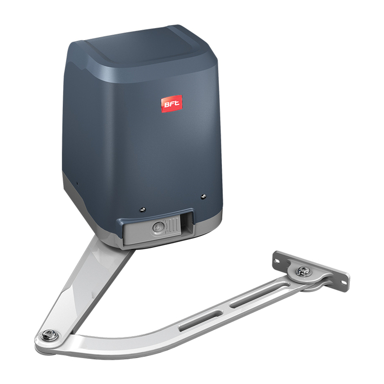
  9. BFT VISTA SW SXL User manual

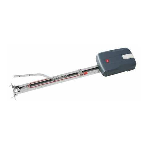
BFT VISTA SW SXL User manual

Other manuals for VISTA SW SXL

1

Other BFT Door Opening System manuals

BFT VISTA EMERGENCY User manual

BFT

BFT VISTA EMERGENCY User manual

BFT PHOBOS BT A25 User manual

BFT

BFT PHOBOS BT A25 User manual

BFT ARGO User manual

BFT

BFT ARGO User manual

BFT RTD User manual

BFT

BFT RTD User manual

BFT BOTTICELLI User manual

BFT

BFT BOTTICELLI User manual

BFT VISTA SW 260 SXL User manual

BFT

BFT VISTA SW 260 SXL User manual

BFT KIT P.B. BL-SMALL XTREME 35 User manual

BFT

BFT KIT P.B. BL-SMALL XTREME 35 User manual

BFT SPC User manual

BFT

BFT SPC User manual

BFT OBERON TRI A2000 INV User manual

BFT

BFT OBERON TRI A2000 INV User manual

BFT K 130 User manual

BFT

BFT K 130 User manual

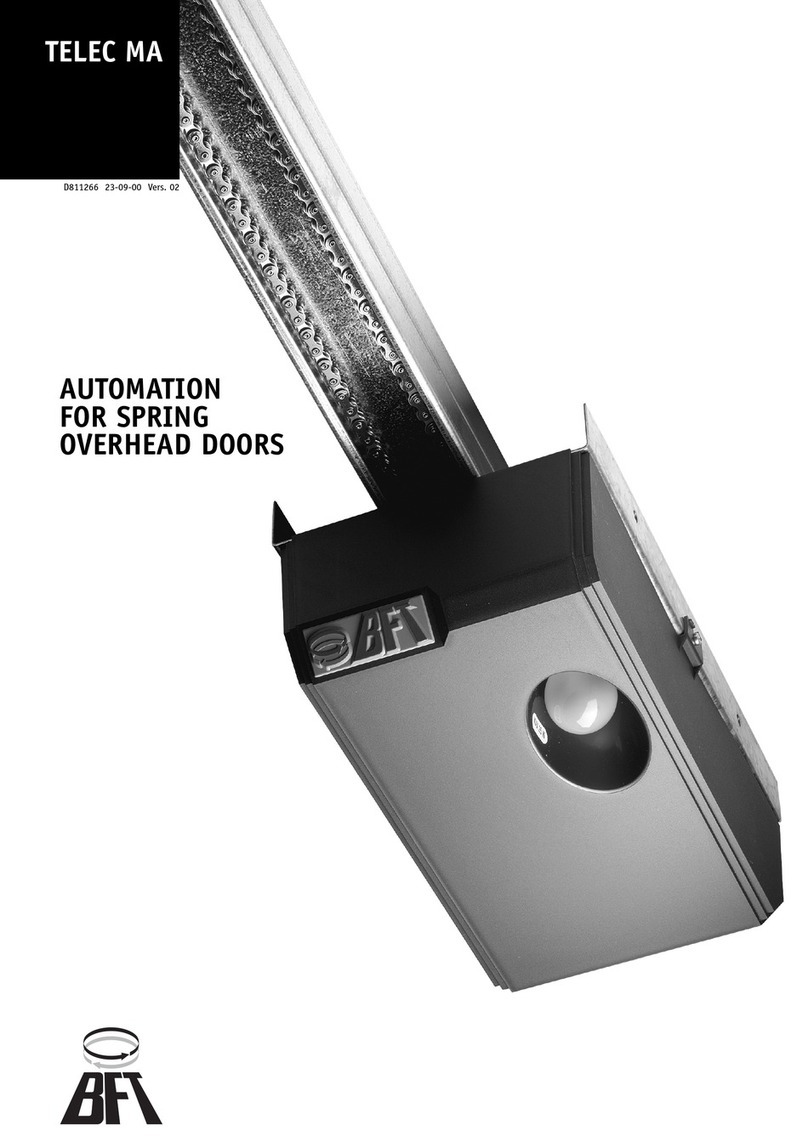
BFT TELEC MA User manual

BFT

BFT TELEC MA User manual

BFT VISTA-SL Series User manual

BFT

BFT VISTA-SL Series User manual

BFT MOOVI GA User manual

BFT

BFT MOOVI GA User manual

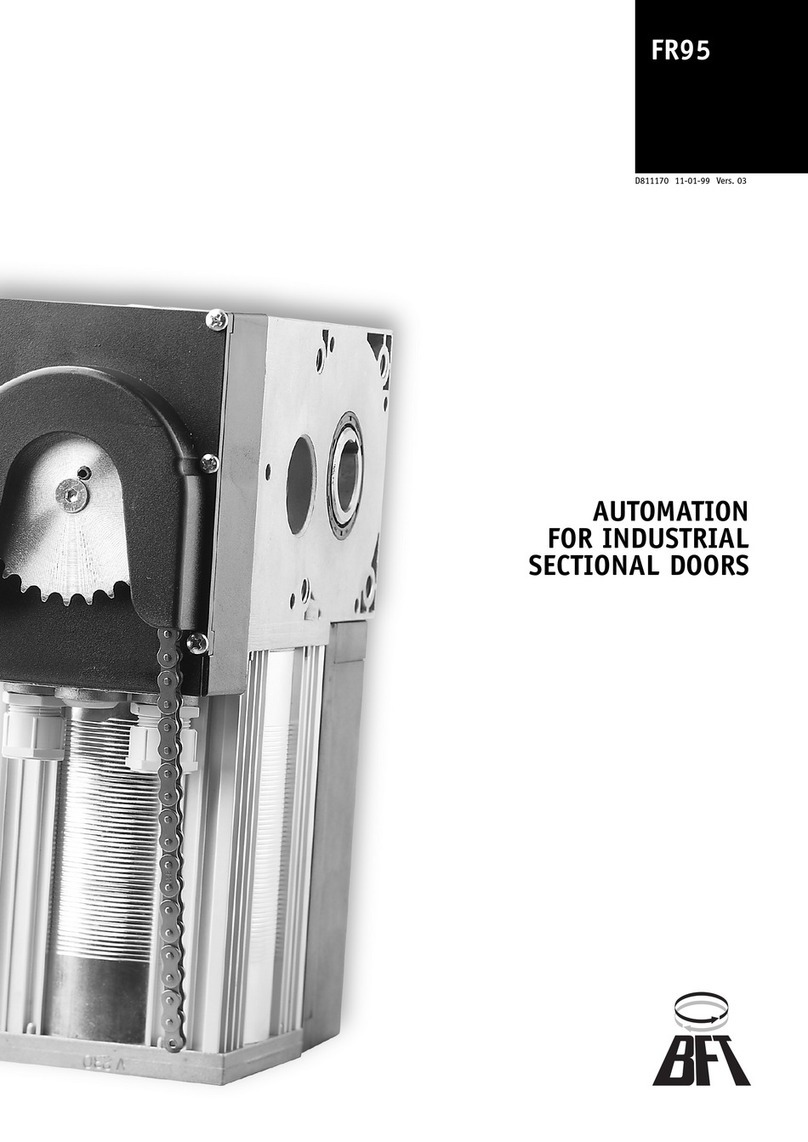
BFT FR95 Series User manual

BFT

BFT FR95 Series User manual

BFT VISTA-SLE User manual

BFT

BFT VISTA-SLE User manual

BFT SUB EL User manual

BFT

BFT SUB EL User manual

BFT LUX BT 2B User manual

BFT

BFT LUX BT 2B User manual

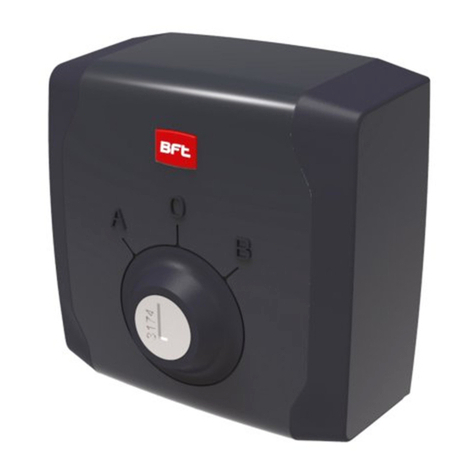
BFT Q.BO KEY User manual

BFT

BFT Q.BO KEY User manual

BFT CLONIX1 User manual

BFT

BFT CLONIX1 User manual

BFT ELI-250 User manual

BFT

BFT ELI-250 User manual

BFT BRCT User manual

BFT

BFT BRCT User manual

BFT WIND RMB 130B 200 User manual

BFT

BFT WIND RMB 130B 200 User manual

BFT VISTA SW 260 SXL User manual

BFT

BFT VISTA SW 260 SXL User manual

BFT X 180 User manual

BFT

BFT X 180 User manual

Popular Door Opening System manuals by other brands

Mobeye Call-Key MCK100 installation manual

Mobeye

Mobeye Call-Key MCK100 installation manual

SALICE Lapis Assembly instructions

SALICE

SALICE Lapis Assembly instructions

Cal-Royal N-F77CVR Installation instruction

Cal-Royal

Cal-Royal N-F77CVR Installation instruction

Scrigno OPEN1000 Assembly manual

Scrigno

Scrigno OPEN1000 Assembly manual

Alecto ADI-250 user manual

Alecto

Alecto ADI-250 user manual

Besam Swingmaster MP Installation, adjustment and maintenance instructions

Besam

Besam Swingmaster MP Installation, adjustment and maintenance instructions

Assa Abloy SARGENT 1431 Series instructions

Assa Abloy

Assa Abloy SARGENT 1431 Series instructions

GAL MOVFR Quick setup

GAL

GAL MOVFR Quick setup

Häfele Finetta T 70 VF manual

Häfele

Häfele Finetta T 70 VF manual

AGS D-PL Instructions for fitting, operating and maintenance

AGS

AGS D-PL Instructions for fitting, operating and maintenance

Stanley MA900ñ Installation and owner's manual

Stanley

Stanley MA900ñ Installation and owner's manual

WITTUR Hydra Plus UD300 Instruction handbook

WITTUR

WITTUR Hydra Plus UD300 Instruction handbook

Alutech TR-3019-230E-ICU Assembly and operation manual

Alutech

Alutech TR-3019-230E-ICU Assembly and operation manual

Pamex KT-INP35 Installation instruction

Pamex

Pamex KT-INP35 Installation instruction

MPC ATD ACTUATOR 50 ATD-313186 Operating and OPERATING AND INSTALLATION Manual

MPC

MPC ATD ACTUATOR 50 ATD-313186 Operating and OPERATING AND INSTALLATION Manual

Chamberlain T user guide

Chamberlain

Chamberlain T user guide

Dorma MUTO COMFORT M DORMOTION 50 Mounting instruction

Dorma

Dorma MUTO COMFORT M DORMOTION 50 Mounting instruction

Fireco Dorgard operating guide

Fireco

Fireco Dorgard operating guide

manuals.online logo
manuals.online logoBrands
  • About & Mission
  • Contact us
  • Privacy Policy
  • Terms and Conditions

Copyright 2025 Manuals.Online. All Rights Reserved.

ISTRUZIONI D’USO E DI INSTALLAZIONE
INSTALLATION AND USER’S MANUAL
INSTRUCTIONS D’UTILISATION ET D’INSTALLATION
INSTALLATIONS-UND GEBRAUCHSANLEITUNG
INSTRUCCIONES DE USO Y DE INSTALACION
GEBRUIKS- EN INSTALLATIEAANWIJZINGEN
D812034 00100_03 04-12-14
AUTOMAZIONI PORTE
AUTOMATION DOORS
AUTOMATIONS POUR PORTES
AUTOMATICTUREN
AUTOMATIZACIONES PARA PUERTAS
AUTOMATISERINGSSYSTEMEN DEUREN
Attenzione! Leggere attentamente le “Avvertenze” all’interno! Caution! Read “Warnings” inside carefully! Attention! Veuillez lire attentivement les Avertissements qui se trouvent à l’intérieur!
Achtung! Bitte lesen Sie aufmerksam die„Hinweise“ im Inneren! ¡Atención¡ Leer atentamente las“Advertencias”en el interior! Let op! Lees de“Waarschuwingen”aan de binnenkant zorgvuldig!
VISTA SW SXL
www.BFTGateOpeners.com
(800) 878-7829
D812034 00100_03
D812034 00100_03
2 - VISTA SW SXL
BRACCIO A SLITTA / SLIDE ARM / BRAS À GLISSIÈRE
SCHLITTENARM/ BRAZO DE CORREDERA/ SCHUIFARM
BRACCIO ARTICOLATO / DOUBLE LEVER ARM/ BRAS ARTICULÉ
GELENKARM/ BRAZO ARTICULADO/ SCHARNIERARM
BRACCIO ARTICOLATO LUNGO / LONG DOUBLE LEVER ARM /BRAS ARTICULÉ
LANGER GELENKARMLUNGO LONG/BRAZO ARTICULADO LARGO/ANGE SCHARNIERARM
2
230V ~
3
3
x1.5 mm
3x1.5 mm
2
ON/OFF
x0.5
mm
2
8x0.22mm
2
PREDISPOSIZIONE DELL’IMPIANTO ELETTRICO/ ELECTRICAL SYSTEM SETUP
PRÉDISPOSITION DE L’INSTALLATION ÉLECTRIQUE / VORBEREITUNG DER ELEKTISCHEN ANLAGE
PREPARACIÓN DE LA INSTALACIÓN ELÉCTRICA / VOORBEREIDING VAN DE ELEKTRISCHE INSTALLATIE
AVISTA SW SXL - VISTA SW MXL
B
C
56
676
13
12.5
20
55
55
25
12.5
220
94
88
134
Peso dell’anta (kg) / Door weight (kg)/ Poids du vantail (kg)
Gewicht des Flügels (kg)/ Peso de la hoja (kg)/ Gewicht van de deur (kg)
Larghezza dell’anta (m) / Door leaf width (m) / Largeur du vantail (m)
Breite des Flügels (m) / Anchura de la hoja (m) / Breedte van de deur (m)
Passaggio cavi / Cable routing
Passage des câbles / Kageldurchführung
Paso de los cables / Kabeldoorgang
C1
0÷150 mm
150÷300 mm
+100
-50
D812034 00100_03D812034 00100_03
VISTA SW SXL - 3
ENGLISH
Smontaggio Automazione/ Dismantling the Automatic Door Operator / Démontage Automatisation
Ausbau der Automatisierung/ Desmontaje Automatización / Demontage Automatiseringssysteem
*
*
*
*
V1
7
*
3
3
V3
V3
6
5
1
V2
*
8
V4
2
V2
4
4
V4
2
VISTA SW SXL VISTA SW MXL
11
14
9
13
12
*Non in dotazione.
Not supplied.
Ne sont pas fournis.
Nicht im lieferum.
No asignadas en
el equipamiento base.
Niet meegeleverd.
2
*Non in dotazione
Not supplied
Ne sont pas fournis
Nicht im lieferum
No asignadas en el equipamiento base
Niet meegeleverd
M6
Fissaggio Trave / Fastening the header / Fixation poutres/
Befestigung des Trägers/ Fijación viga/ Bevestiging dwarsdrager
2A 2B 2C
*
V2
M6
20
4,8
9,5
V1
M4
10
V3
M6
10
V4
*
standard/ estándar
standaard
P111563 00001
10
P111563 00002
P111563 00004P111563 00003
L=90 L=50
L=70
1
D812034 00100_03
D812034 00100_03
4 - VISTA SW SXL
8
16
6
12
8.4
13
Installazione Braccio Rigido / Installing the Single Lever Arm / Installation du Bras Rigide / Installation des starren Arms
Instalación Brazo Rígido/ Installatie Scharnierloze arm
Posizionamento braccio /Arm positioning/ Positionnement bras/
Positionierung des Arms/ Posicionamiento brazo/ Plaatsen van de arm
Precarico molla/Spring preload/ Préchargement ressort/
Vorspannung der Feder/ Precarga muelle / Voorbelasting van de veer
Regolazione Molla/Spring adjustment/ Réglage ressort/
Einstellung der Feder/ Regulación muelle
Afstelling van de veer
D
Asse motoriduttore
Gearmotor Axis
Axe motoréducteur
Achse Getriebemotor
Eje motorreductor
As reductiemotor
Asse motoriduttore
Gearmotor Axis
Axe motoréducteur
Achse Getriebemotor
Eje motorreductor
As reductiemotor
Traversa
Header
Entretoise
Querträger
travesaño
Dwarsdrager
Asse cerniera
Hinge axis
Axe charnière
Achse des Scharniers
Eje bisagra
Scharnieras
R1
V1
D3 D4
D5
Braccio rigido
Single lever arm
Bras rigide
Starrer Arm
Brazo rígido
Scharnierloze arm
600
180
15
*
*
V2
R1
V1
V2
35
+100-50
56
L+5
L+5
Asse motoriduttore
Gearmotor Axis
Axe motoréducteur
Achse Getriebemotor
Eje motorreductor
As reductiemotor
Braccio rigido
Single lever arm
Bras rigide
Starrer Arm
Brazo rígido
Scharnierloze arm
600
180
15
L+5
Guida
guide
Führung
Guía
Geleider
Guida
guide
Führung
Guía
Geleider
L
standard/ estándar
standaard
P111563 00001
P111563 00002 P111563 00004P111563 00003
L=90
L=50
L=70
Vedere/See / Cf. /Siehe/ Véase /Zie Fig. D
220 220
Assemblaggio Guida/Fitting the guide
Assemblage rail/
Montage der Führung
Ensamblaje guía/ Montage geleider
D2
V1
V1 9.5
2.9
D1
Braccio NON preforato / Arm NOT pre-drilled / Bras PAS pré-percé
NICHT vorgebohrter Arm / Brazo NO perforado / NIET geperforeerde arm
12 47
19
*
*
D812034 00100_03D812034 00100_03
VISTA SW SXL - 5
E
E2
E1
L
standard/ estándar
standaard
P111563 00001
P111563 00002 P111563 00004P111563 00003
L=90
L=50
L=70
Fissaggio braccio all’anta / Fastening the arm to the door leaf
Fixation bras sur vantail /
Befestigung des Arms am Flügel
Fijación brazo a la hoja /
Bevestiging arm aan de deur
Fissaggio braccio all’automazione /Fastening the arm to the
automatic door operator/ Fixation bras sur l’automatisation/
Befestigung des Arms an der Automatisierung/
Fijación brazo a la automatización/ Bevestiging arm aan het automatiseringssysteem
Traversa
Header
Entretoise
Querträger
travesaño
Dwarsdrager
220
Asse motoriduttore
Gearmotor Axis
Axe motoréducteur
Achse Getriebemotor
Eje motorreductor
As reductiemotor
Asse cerniera
Hinge axis
Axe charnière
Achse des Scharniers
Eje bisagra
Scharnieras
L-22
27
55
56
292.5
Attacco anta
Door leaf
Attachment tting
Raccord vantail
Fijación hoja
Bevestiging deur
220
Asse motoriduttore
Gearmotor Axis
Axe motoréducteur
Achse Getriebemotor
Eje motorreductor
As reductiemotor
L-22
27
55292.5
Attacco anta
Door leaf
Attachment tting
Raccord vantail
Fijación hoja
Bevestiging deur
Asse motoriduttore
Gearmotor Axis
Axe motoréducteur
Achse Getriebemotor
Eje motorreductor
As reductiemotor
27
0÷300
L-22
E4
E3
Regolazione Molla/Spring adjustment
Réglage ressort/ Einstellung der Feder
Regulación muelle / Afstelling van de veer
Vedere / See
Cf. /Siehe
Véase /Zie
Fig. D
18
*
*
90°
12
16
8.4
16
6
8
8
R1
V2
V3
V1
V1
V2
V3
R1
ß/2
ß/2
ß
Installazione Braccio Articolato /Installing the double lever arm/ Installation bras articulé
Installation des Gelenkarms/ Instalación brazo articulado/ Installatie scharnierarm
21
9
80
55
6.5
7,5
3
*
*
Regolazione braccio /Arm adjustment / Réglage bras
Einstellung des Arms / Regulación brazo / Afstelling van de arm
ENGLISH
D812034 00100_03
D812034 00100_03
6 - VISTA SW SXL
MIN
MAX
Collegamenti VISTA SW SXL/ VISTA SW SXL connections/ Connexions VISTA SW SXL
Anschlüsse VISTA SW SXL/ Conexiones VISTA SW SXL / Aansluitingen VISTA SW SXL
Collegamenti VISTA SW MXL / VISTA SW MXL connections / Connexions VISTA SW MXL
Anschlüsse VISTA SW MXL/ Conexiones VISTA SW MXL/ Aansluitingen VISTA SW MXL
Interruttore selezione logiche / Logic selection switch
Interrupteur sélection logiques / Schalter Auswahl der Logiken
Interruptor selección lógicas / Schakelaar keuze logica’s
1
910 11 12 13 14
2 3 4 5 6 7 8
10
1
915 11
2 3 4 5 6 7
1213
28V
0V
Interruttore ON/OFF // ON/OFF switch
Interrupteur ON/OFF// Schalter ON/OFF
Interruptor ON/OFF // ON/OFF schakelaar
Selezione livello frenatura
Braking level selection
Sélection niveau de freinage
Auswahl des Bremspegels
Selección nivel frenado
Keuze remniveau
1.Display e pulsanti
2. Dip Switchs
3. Connettore uscite ausiliarie
4. Connettori comandi/ingressi
5. Alimentazione Sensori/Accessori
6. Connettore seletore multilogiche
7. Connettore elettroserratura
8. Connettore Selezione livello freno
9. Connettore trasformator
10. Connettore interruto ON-OFF
11.
Connettore interruttore selezioni logiche
12. Connettore encoder
13. Connettore motore
14. Selettore tipologie braccio
15. Connettore batterie
1.Display and pushbuttons
2.Dip switches
3.Auxiliary outputs connector
4.Inputs/commands connectors
5.Sensors/Accessories Power Supply
6.Multilogic selector connector
7.Solenoid lock connector
8.Brake level selection connector
9.Transformer connector
10.ON-OFF switch connector
11.Logic selection switch connector
12.Encoder connector
13.Motor connector
14.Arm type selector
15.Battery connector
1. Acheur et touches
2. Commutateurs Dip
3. Connecteur sorties auxiliaires
4. Connecteurs commandes/entrées
5. Alimentation Capteurs/Accessoires
6. Connecteur sélecteur multilogiques
7. Connecteur serrure électrique
8. Connecteur Sélection niveau frein
9. Connecteur transformateur
10. Connecteur interrupteur ON-OFF
11.
Connecteur interrupteur sélections logiques
12. Connecteur encodeur
13. Connecteur moteur
14. Sélecteur types de bras
15. Connecteur batteries
1.Display und Tasten
2.DIP-Switches
3.Steckverbindung Hilfsausgänge
4.Steckverbindungen Befehle/Eingänge
5.Stromversorgung Sensoren/Zubehör
6.Steckverbindung Wahlschalter Multilogiken
7.Steckverbindung Elektroschloss
8.Steckverbindung Auswahl des Bremspegels
9.Steckverbindung Transformator
10.Steckverbindung Schalter ON-OFF
11.Steckverbindung Schalter Auswahl Logiken
12.Steckverbindung Encoder
13.Steckverbindung Motor
14.Steckverbindung Armtyp
15.Steckverbindung Batterien
1.Pantalla y pulsadores
2 Conmutadores DIP
3.Conectores salidas auxiliares
4.Conectores mandos/entradas
5.Alimentación Sensores/Accesorios
6.Conector selector multilógicas
7.Conector cerradura eléctrica
8.Conector Selección nivel freno
9.Conector transformador
10.Conector interruptor ON-OFF
11.Conector interruptor selecciones lógicas
12.Conector encoder
13.Conector motor
14.Selector tipologías brazos
15.Conector baterías
1.Display en knoppen
2.Dip Switches
3.Connector secundaire outputs
4.Connectors commando’s/inputs
5.Voeding Sensors/Accessoires
6.Connector keuzeschakelaar multilogica’s
7.Connector elektroslot
8.Connector Keuze remniveau
9.Connector transformator
10.Connector ON-OFF schakelaar
11.Connector schakelaar logische selecties
12.Connector encoder
13.Connector motor
14.Keuzeschakelaar armtypes
15.Connector batterijen
N
M
L
GI
O
MANUALE / MANUAL
MANUEL/ MANUELL
MANUAL/ HANDMATIG
DUE RADAR/TWO RADARS
DEUX RADARS/ ZWEI RADAR
DUE RADAR / TWEE RADARS
STOP APERTO/ STOP OPEN
ARRÊT À L’AIR LIBRE
STOPP BEI ÖFFNUNG
STOP ABIERTO/ STOP OPEN
STOP CHIUSO/ STOP CLOSED
ARRÊT FERMÉ
STOPP GESCHLOSSEN
STOP CERRADO/ STOP GESLOTEN
DUE RADAR/TWO RADARS DEUX
RADARS/ ZWEI RADAR DUE
RADAR / TWEE RADARS
STOP APERTO/ STOP OPEN
ARRÊT À L’AIR LIBRE
STOPP BEI ÖFFNUNG
STOP ABIERTO/ STOP OPEN
VISTA SW SXL VISTA SW MXL
Selezione tipologia braccio
Arm type selection
Sélection type de bras
Auswahl des Armtyps
Selección tipología brazo
Keuze armtypes
H
D812034 00100_03
+-
++
TEST
-
OPEN SAFETY
-
A
B
A
B
AUX-OUT 1
AUX-OUT 2
COM
COM
OUT
15 VDC
COM
RST
PWF
DATA
GND
LOCK
PHOT OP
AUX-IN 1
AUX-IN 2
PHOT CL
KEY
RADAR EXT.
RADAR INT.
A
B
A
B
AUX-OUT 1
AUX-OUT 2
COM
COM
OUT
15 VDC
COM
RST
PWF
DATA
GND
LOCK
PHOT OP
AUX-IN 1
AUX-IN 2
PHOT CL
KEY
RADAR EXT.
RADAR INT.
+-
+TEST
-
OPEN SAFETY
OPEN SAFETY
+-
OUT 15 V
OUT 15 V
+OUT 15 V
17 = 0
30 = 1
A
B
+OUT 15 V
18 = 0
31 = 1
A
B
P
R
Collegamento sensori rilevamento / sicurezza con verica in apertura // Connecting detectors/safety sensors with testing during opening
Connexion capteurs détection/sécurité avec vérication à l’ouverture// Verbindung Sensoren Erfassung/Sicherheit mit Überprüfung bei Önung
Conexión sensores detección/seguridad con control en fase de apertura // Aansluiting detectie/veiligheid sensors met controle bij openen
Collegamento sensori rilevamento / sicurezza con verica in chiusura
Connecting detectors/safety sensors with testing during closing
Connexion capteurs détection/sécurité avec vérication à la fermeture
Verbindung Sensoren Erfassung/Sicherheit mit Überprüfung bei Schließung
Conexión sensores detección/seguridad con control en fase de cierre
Aansluiting detectie/veiligheid sensors met controle bij sluiten
1
2
Installazione Vista SW Doppio / Installing pair of VISTA SW operators/ Installation VISTA SW double/ Doppelte Installation VISTA SW
Instalación VISTA SW doble/ Installatie dubbele VISTA SW
Q
S
T
Non in dotazione
Not supplied
Ne sont pas fournis
Nicht im lieferum
No asignadas en el equipamiento base
Niet meegeleverd
Peso dell’anta (kg) / Door weight (kg)/ Poids du vantail (kg)
Gewicht des Flügels (kg)/ Peso de la hoja (kg)
Gewicht van de deur (kg)
Larghezza dell’anta (m) / Door leaf width (m) / Largeur du vantail (m)
Breite des Flügels (m) / Anchura de la hoja (m) / Breedte van de deur (m)
Installazione batterie / Installing the batteries
Installation batteries/ Installation der Batterien
Instalación baterías/ Installatie batterijen
V1
VISTA SW MXL
Scheda caricabatteria / Battery charger board
Carte chargeur de batterie / Batterieladekarte
Tarjeta cargador de baterías / Kaart batterijoplader
V1
VISTA SW SXL - 7
D812034 00100_03
8 - VISTA SW SXL
3
V1
V1
D1
D1
M4
D1
1
2
Asse cerniera destra
Right hinge axis
Axe charnière droite
rechte Scharnierachse
Eje bisagra derecha
As scharnier rechts
Asse cerniera sinistra
Left hinge axis
Axe charnière gauche
linke Scharnierachse
Eje bisagra izquierda
As scharnier links
Collegamento ad uso interblocco / Connection for interlocking feature / Connexion pour interverrouillage
Verbindung mit Verwendung Verblockung / Conexión con uso interbloqueo/ Aansluiting voor interlock gebruik
Scheda con priorità / Board with priority / Carte avec priorité
Karte mit Vorrang / Tarjeta con prioridad / Kaart met voorrang
15 = 2
17 = 1
Scheda senza priorità/ Board without priority
Carte sans priorité/ Karte Ohne Vorrang
Tarjeta sin prioridad/ Kaart zonder voorrang
15 = 3
17 = 1
Togliere Jumper / Remove jumper
Retirer Cavalier / Jumper entfernen
Quitar el Jumper / Jumper verwijderen
U
AA
AB
MASTER
MASTER
1
2
SLAVE
3
Scheda master / Master board/ Carte master
Karte Master/ Tarjeta master / Master kaart
13 = 1
Scheda slave / Slave board
Carte slave/Karte Slave
Tarjeta slave/ Slave kaart
13 = 2
Collegamento VISTA SEL
SW (opzionale)*
* VISTA SEL SW connection (option) / Connexion VISTA SEL SW (option) / Verbindung VISTA SEL SW (Option)/ Conexión VISTA SEL SW (opcional) / Aansluiting VISTA SEL SW (optie)
1
3
2
A
B
A
B
AUX-OUT 1
AUX-OUT 2
COM
COM
OUT
15 VDC
COM
RST
PWF
DATA
GND
LOCK
PHOT OP
AUX-IN 1
AUX-IN 2
PHOT CL
KEY
RADAR EXT.
RADAR INT.
A
B
A
B
AUX-OUT 1
AUX-OUT 2
COM
COM
OUT
15 VDC
COM
RST
PWF
DATA
GND
LOCK
PHOT OP
AUX-IN 1
AUX-IN 2
PHOT CL
KEY
RADAR EXT.
RADAR INT.
A
B
A
B
AUX-OUT 1
AUX-OUT 2
COM
D812034 00100_03
VISTA
SW
SXL
- 9
ENGLISH
INSTALLATION MANUAL
INSTALLER WARNINGS
Anything that is not explicitly provided for in the installation ma-
nual is not allowed. The operator’s proper operation can only be
guaranteed if the information given is complied with. The Firm shall
not be answerable for damage caused by failure to comply with the
instructions featured herein.
Whilewewillnotaltertheproduct’sessentialfeatures,theFirmreserves
the right, at any time, to make those changes deemed opportune to
improve the product from a technical, design or commercial point of
view, and will not be required to update this publication accordingly.
WARNING! Important safety instructions. Carefully read and comply with
all the warnings and instructions that come with the product as incorrect
installationcan cause injury to people andanimalsanddamage to property.
Thewarnings and instructionsgiveimportantinformation regarding safety,
installation, use and maintenance. Keep hold of instructions so that you can
attach them to the technical le and keep them handy for future reference.
GENERAL SAFETY
This product has been designed and built solely for the purpose indicated herein.
Uses other than those indicated herein might cause damage to the product and
create a hazard.
-Theunitsmakingup the machineanditsinstallationmust meet therequirements
of the following European Directives, where applicable: 2004/108/EC, 2006/95/
EC, 2006/42/EC, 89/106/EC, 99/05/EC and later amendments. For all countries
outside the EEC, it is advisable to comply with the standards mentioned, in ad-
dition to any national standards in force, to achieve a good level of safety.
-The Manufacturer of this product (hereinafter referred to as the “Firm”) disclaims
all responsibility resulting from improper use or any use other than that for
which the product has been designed, as indicated herein, as well as for failure
to apply Good Practice in the construction of entry systems (doors, gates, etc.)
and for deformation that could occur during use.
-Installation must be carried out by qualied personnel (professional installer,
according to EN 12635), in compliance with Good Practice and current code.
-Before installing the product, make all structural changes required to produce
safety gaps and to provide protection from or isolate all crushing, shearing and
dragging hazard areas and danger zones in general in accordance with the
provisions of standards EN 16005 or any local installation standards. Check that
the existing structure meets the necessary strength and stability requirements.
-Before commencing installation, check the product for damage.
-The Firm is not responsible for failure to apply Good Practice in the construction
and maintenance of the doors, gates, etc. to be motorized, or for deformation
that might occur during use.
-Make sure the stated temperature range is compatible with the site in which
the automated system is due to be installed.
-Do not install this product in an explosive atmosphere: the presence of am-
mable fumes or gas constitutes a serious safety hazard.
-Disconnect the electricity supply before performing any work on the system.
Also disconnect buer batteries, if any are connected.
-Before connecting the power supply, make sure the product’s ratings match the
mains ratings and that a suitable residual current circuit breaker and overcurrent
protection device have been installed upline from the electrical system. Have
the automated system’s mains power supply tted with a switch or omnipolar
thermal-magnetic circuit breaker with a contact separation that meets code
requirements.
-Make sure that upline from the mains power supply there is a residual current
circuit breaker that trips at no more than 0.03A as well as any other equipment
required by code.
-Make sure the earth system has been installed correctly: earth all the metal parts
belonging to the entry system (doors, gates, etc.) and all parts of the system
featuring an earth terminal.
-Installation must be carried out using safety devices and controls that meet
standards EN 12978 and EN 16005.
-Impact forces can be reduced by using deformable edges.
-Intheeventimpactforcesexceedthevalueslaiddown by the relevant standards,
apply electro-sensitive or pressure-sensitive devices.
-Apply all safety devices (photocells, safety edges, etc.) required to keep the
area free of impact, crushing, dragging and shearing hazards. Bear in mind the
standards and directives in force, Good Practice criteria, intended use, the instal-
lation environment, the operating logic of the system and forces generated by
the automated system.
-Apply all signs required by current code to identify hazardous areas (residual
risks). All installations must be visibly identied.
-Once installation is complete, apply a nameplate featuring the door/gate’s data.
-If the automated system is installed at a height of less than 2.5 m or is accessible,
the electrical and mechanical parts must be suitably protected.
-Install any xed controls in a position where they will not cause a hazard, away
from moving parts. More specically, hold-to-run controls must be positioned
within direct sight of the part being controlled and, unless they are key operated,
must be installed at a height of at least 1.5 m and in a place where they cannot
be reached by the public.
-Attach a label near the operating device, in a permanent fashion, with informa-
tion on how to operate the automated system’s manual release.
-Make sure that, during operation, mechanical risks are avoided or relevant
protective measures taken and, more specically, that nothing can be banged,
crushed, caught or cut between the part being operated and surrounding parts.
-Once installation is complete, make sure the motor automation settings are
correct and that the safety and release systems are working properly.
-Only use original spare parts for any maintenance or repair work. The Firm dis-
claims all responsibility for the correct operation and safety of the automated
system if parts from other manufacturers are used.
-Do not make any modications to the automated system’s components unless
explicitly authorized by the Firm.
-Instruct the system’s user on what residual risks may be encountered, on the
control systems that have been applied and on how to open the system manu-
ally in an emergency. give the user guide to the end user.
-Dispose of packaging materials (plastic, cardboard, polystyrene, etc.) in accord-
ance with the provisions of the laws in force. Keep nylon bags and polystyrene
out of reach of children.
WIRING
WARNING! For connection to the mains power supply, use: a multicore cable
with a cross-sectional area of at least 5x1.5mm2or 4x1.5mm2when dealing
with three-phase power supplies or 3x1.5mm2for single-phase supplies (by
way of example, type H05 VV-F cable can be used with a cross-sectional area
of 4x1.5mm2). To connect auxiliary equipment, use wires with a cross-sectional
area of at least 0.5 mm2.
- Only use pushbuttons with a capacity of 10A-250V or more.
- Wiresmust be secured with additionalfasteningneartheterminals (for example,
using cable clamps) in order to keep live parts well separated from safety extra
low voltage parts.
- During installation, the power cable must be stripped to allow the earth wire
to be connected to the relevant terminal, while leaving the live wires as short
as possible. The earth wire must be the last to be pulled taut in the event the
cable’s fastening device comes loose.
WARNING! safety extra low voltage wires must be kept physically separate from
low voltage wires.
Only qualied personnel (professional installer) should be allowed to access
live parts.
CHECKING THE AUTOMATED SYSTEM AND MAINTENANCE
Beforethe automated systemisnallyput into operation,andduringmaintenance
work, perform the following checks meticulously:
-Make sure all components are fastened securely.
-Check starting and stopping operations in the case of manual control.
-Check the logic for normal or personalized operation.
-Check that all safety devices are working properly and that the anti-crush safety
device (if tted) is set correctly.
-Impact forces can be reduced by using deformable edges.
-Make sure that the emergency operation works, where this feature is provided.
-Check opening and closing operations with the control devices applied.
-Check that electrical connections and cabling are intact, making extra sure that
insulating sheaths and cable glands are undamaged.
- While performing maintenance, clean the sensors’ optics.
- When the automatic door operator is out of service for any length of time,
activate the emergency release (see “EMERGENCY OPERATION” section) so
that the operated part is made idle, thus allowing the door to be opened and
closed manually.
-
If the power cord is damaged, it must be replaced by the manufacturer or their
technical assistance department or other such qualied person to avoid any risk .
-The maintenance described above must be repeated at least once yearly or at
shorter intervals where site or installation conditions make this necessary.
WARNING!
Remember that the drive is designed to make the gate/door easier to use and
will not solve problems as a result of defective or poorly performed installation
or lack of maintenance
SCRAPPING
Materials must be disposed of in accordance with the regulations in
force. Do not throw away your discarded equipment or used batteries
with household waste. You are responsible for taking all your waste
electrical and electronic equipment to a suitable recycling centre.
DISMANTLING
Ifthe automated system is beingdismantledinorderto be reassembled at another
site, you are required to:
-Cut o the power and disconnect the whole electrical system.
-Remove the actuator from the base it is mounted on.
-Remove all the installation’s components.
-See to the replacement of any components that cannot be removed or happen
to be damaged.
THE DECLARATION OF CONFORMITY CAN BEVIEWED ON THIS WEBSITE:
WWW.BFT.IT IN THE PRODUCT SECTION.
AVVERTENZE INSTALLATORE (PORTE) D812061 00200_02
D812034 00100_03
10 - VISTA SW SXL
INSTALLATION MANUAL
1) GENERAL INFORMATION
Motorized header for automatic swing doors, complete with control panel. Ac-
cessories available for producing a complete installation.
2) TECHNICAL SPECIFICATIONS
MECHANICAL SPECIFICATIONS
Leaf width min. 700mm max. 1400mm
Leaf weight see Fig. R
Opening speed max. 70°/s - min. 20°/s (3 - 6 sec.)
Closing speed max. 40°/s - min. 10°/s (4 - 15 sec.)
Max. opening angle 110°
Header size See Fig. B
Actuator weight 11 kg
ELECTRICAL SPECIFICATIONS
Power supply 220 - 230V~ ±10%, 50/60 Hz single phase
Fuses see Fig. G
Accessories power supply 15Vdc - max. 12W
Rated power 85W
Temperature range from -10°C to + 50°C (inside cover)
Operating cycle Continuous at 25°C
Anti-crush Anti-crush safety device when
obstacles are detected
Backup batteries (optional extras) 2 x 12V 1.2Ah
Protection rating IP 40
3) PREPARING THE ELECTRICAL SYSTEM
Prepare the electrical system (Fig. A), referring to the standards in force. Keep
mains power connections well separated from service connections (photocells,
safetyedges,controldevices,etc.).Keep mainspowerconnections wellseparated
from safety extra low voltage connections.
4) IDENTIFICATION OF PARTS Fig. 1
The VISTA SW automatic door operator comprises:
1. Load-bearing aluminium header
2. Power supply unit
3. Microprocessor-based control unit
4. DC gearbox
5. End panel on power unit end
6. End panel on gearmotor end
7. Anodized aluminium cover
The following optional accessories are available to complete installation:
8. BBV SW MXL backup batteries kit for VISTA SW MXL only
9. VISTA SEL SW Digital function control station
10. EXT ASW XL 30-50-70-90 arm attachment ttings
11. TSWP XL PROFILES for VISTA SW IN PAIR(see FIG. U)
12. ASW XL ART
13. ASW XL ARTL
14. ASW XL
5) FASTENING METHOD
- Dismantling the parts Fig. 1
- Fastening the load-bearing header Fig. 2
- Cable routing Fig. B
- Reassembling the parts Fig. 1
7) INSTALLATION OPTIONS Fig. C
- With SLIDE ARM, pull option; use when automatic door operator is installed
on the pull side).
- With DOUBLE LEVER ARM, push option; use when automatic door operator
is installed on the push side).
7.1) INSTALLING THE SLIDE ARM Fig. D
- D1. Fasten the guide on the door leaf
- D2. Assemble the guide
- D3. Remove the arm, slide out the arm attachment tting, rotate it by 1 or 2
teeth in the direction the door closes and t it back in the shaft (for VISTA
SW SXL only). Fasten the arm.
- D4. With the door closed, insert the arm in the automatic door operator’s shaft,
lining up the other end with the slide’s axis.
- D5. Adjust the spring to level 4 (for VISTA SW SXL only).
7.2) INSTALLING THE DOUBLE LEVER ARM Fig. E
- E1. Fasten the arm to the leaf.
- E2. Assemble the arm and fasten it to the actuator’s output shaft.
- E3. Adjust the spring to level 4 (for VISTA SW SXL only).
- E4. Loosen screwsV3, position the main arm correctly at a 90° angle to the door
(Fig. E4), rotate the main arm so that the two arms sit at the same angle to
the door, then fasten screws V3.
8) SPRING ADJUSTMENT (for VISTA SW SXL only) Fig. C1
Spring power must be adjusted based on the width of the DOOR leaves and
taking into consideration the power sizes according to standard EN 1154, in the
range from 4 to 6.
9) CONTROL PANEL
9.1) CONNECTIONS Fig. G, L, M
WARNINGS - When performing wiring and installation, refer to the standards
in force and, whatever the case, apply good practice principles.
The wires carrying a very low safe voltage (24V) must be kept physically separate
from low-voltage wires, or they must be suitably insulated with at least 1mm of
additional insulation.
Wiresmust be secured withadditional fasteningnear the terminals,using devices
such as cable clamps.
Terminal Denition Description
L Line
Single-phase power supply 220-
230V~ 50/60 Hz
Earth
N Neutral
Key Locking signal (NC)
Locking signal. If the contact
opens,thecontrolunitcommands
the leaves to close completely.
The signal must be connected
with COM if there are no devices
connected.
RADAR EXT EXT RADAR input (NO) Opening signal. If this contact
closes, the leaves are opened.
RADAR INT INT RADAR input (NO) Opening signal. If this contact
closes, the leaves are opened.
PHOT OP OPENING PHOTOCELL
input (NC)
Opening safety signal. If the door
is opening and the contact opens,
the control unit commands the
door to stop moving immediately.
The signal must be connected
with COM if there are no devices
connected.
PHOT CL CLOSING PHOTOCELL
input (NC)
Closing safety signal. If the door is
closingand thecontact opens,the
control unit commands the door
to reverse immediately. The signal
must be connected with COM if
there are no (internal or external)
devices connected.
COM Commands common
AUX IN 1/2 Auxiliary inputs
congurable
This signal can be set to any of
the conguration options given
for parameters 15 and 16, see
the OPERATING PARAMETER
MANAGEMENT-DISPLAY table
AUX OUT 1/2 Auxiliary outputs
congurable
This signal can be set to any of
the conguration options given
for parameters 17 and 18, see
the OPERATING PARAMETER
MANAGEMENT-DISPLAY table
OUT 15 VDC Peripheral unit power
supply 15Vdc output max. 12W
RST
Serial connection for
Master/Slave connection
and selector
PWF
DATA
GND
LOCK Solenoid lock output
max. 15W
12and24VDCsolenoidlockoutput,
see OPERATING PARAMETER
MANAGEMENT-DISPLAY table,
parameter 09,10