BFT ARGO User manual

ARGO
D811627 00100_02 18/02/09
ISTRUZIONI DI INSTALLAZIONE
INSTALLATION MANUAL
INSTRUCTIONS D’INSTALLATION
MONTAGEANLEITUNG
INSTRUCCIONES DE INSTALACION
INSTALLATIEVOORSCHRIFTEN
AUTOMAZIONI PER PORTE SEZIONALI INDUSTRIALI
OPERATORS FOR INDUSTRIAL SECTIONAL DOORS
AUTOMATISMES POUR PORTES MULTI-LAMES INDUSTRIELLES
AUTOMATISCHE ANTRIEBE FÜR INDUSTRIE-SEKTIONALTORE
AUTOMATISMOS PARA PUERTAS SECCIONALES INDUSTRIALES
AUTOMATISERINGEN VOOR INDUSTRIËLE OPDRACHTGERICHTE DEUREN
ARGO
Attenzione! Leggere attentamente le “Avvertenze” all’interno! Caution! Read “Warnings” inside carefully! Attention! Veuillez lire attentivement les Avertissements qui se trouvent à l’intérieur! Achtung! Bitte lesen Sie
aufmerksam die„Hinweise“ im Inneren! ¡Atención¡ Leer atentamente las“Advertencias” en el interior! Let op! Lees de “Waarschuwingen” aan de binnenkant zorgvuldig!
8027908 347060
https://appceso.com

https://appceso.com

ITALIANO ENGLISH FRANÇAIS ESPAÑOL
NEDERLANDS
DEUTSCH
5
6
7
8
4
3
PREDISPOSIZIONE TUBI, TUBE ARRANGEMENT,
INSTALLATION DES TUBES, VORBEREITUNG DER LEITUNGEN,
DISPOSICIÓN DE TUBOS, VOORINSTELLING BUIZEN
A
C
PHOT
230Volt
2
M
B
1
5 mm
10 mm
10 mm
1
2
SMONTAGGIO CARTER
REMOVING THE COVER
DÉMONTAGE DU CARTER
ABBAU DER VERKLEIDUNG
DESMONTAJE DE CÁRTERES
DEMONTAGE CARTER
V1
20 mm
V2
V1
V2
(Fig. C4)
INSTALLAZIONE VELOCE-QUICK INSTALLATION-INSTALLATION RAPIDE
SCHNELLINSTALLATION-INSTALACIÓN RÁPIDA - SNELLE INSTALLATIE
ARGO - 3
D811627 00100_02
https://appceso.com

Connettore programmatore palmare,
Palmtop programmer connector,
Connecteur programmateur de poche,
Steckverbinder Palmtop-Programmierer,
Conector del programador de bolsillo,
Luce di cortesia,
Courtesy lamp,
Lampe de courtoisie,
Hilfsbeleuchtung,
Luz interior,
16
1234567
8
9
10
11
12
13
14
15
17
Display + tasti programmazione
Display plus programming keys
Afficheur ettouches de programmation
Display und Programmierungstasten
Pantalla más botones de programación
Display meerdere toetsen programmeur
Modulo opzionale SCS-I0, Optional SCS-IO module
Module en option SCS-IO, Optional module SCS-IO
Módulo opcional SCS-IO, Zusatzmodul SCS-IO
Led presenza alimentazione,
PowerON LED,
Voyant LED présence d'alimentation,
Led Vorhandensein Stromversorgung,
Led Presencia de Alimentación,
Led Aanwezigheid voeding
Connettore scheda opzionale
Optional board connector
Connecteur carte facultative
Steckverbinder Zusatzkarte
Conector de la tarjeta opcional
D
1 2 3 4 5 6 7
OUT PROG 2 (NO)
SCA / 2CH (NO)
FAULT PHOT
FAULT BAR
1 2 3 4 5 6 7 8 9 10 11 12 13 14 15 16 17
24VSafe MAX 180mA
OUT PROG 1 (NO)
PARZ./CLOSE
24V MAX 180mA
24V MAX 25W
ANT
SHIELD
START / OPEN
BAR
E
REGOLAZIONE FINECORSA,ADJUSTING THE LIMIT SWITCHES
RÉGLAGE DE LA FIN DE COURSE,EINSTELLUNG DER ENDSCHALTER
REGULACIÓN DE LOS FINALES DE CARRERA,REGELING EINDAANSLAGEN
Fusibile,
Fuse,
Fusible,
Schmelzsicherung,
Fusible,
1,6 AT
Zekering.
Hulplicht.
Connector programmeerbare palmtop. Connector optionele kaart.
DGLCCLBDGL
4 - ARGO
D811627 00100_02
https://appceso.com

F
A
B
.P+
%%1202?BHMSRCPQR?PR
XSDSCEQR?PR?L?BQR?PR
R?QRML?QAMQRMFGBBCL@SRRML
RMSAFCA?AFCCTCPQRR?QRC
PGJ?QAG?PCJC?QC
PCJ?AFCJMQJ?QQCL
QSCJRC
CLB
R?QRMBCQGBCP?RM
BCQGBCPCB@SRRMLRMSAFCBCQGPCC
ECTSCR?QRCRCAJ?BCQC?B?
OK x 2
OK
x 2
+
OK
JMEGA
P?BGM
OK
AUTOSET COPPIA APERTURA-CHIUSURA
OPENING-CLOSING TORQUE AUTOSETTING
RÉGLAGE AUTOMATIQUE COUPLE OUVERTURE-FERMETURE
AUTOSET DREHMOMENT ÖFFNUNG-SCHLIESSUNG
AJUSTE AUTOMATICO DEL PAR EN FASE DE APERTURA-CIERRE
AUTOSET DRAAIMOMENT OPENING - SLUITING.
G
C
D
MEMORIZZAZIONE RADIOCOMANDO
MEMORIZING REMOTE CONTROLS
MÉMORISATION DE LA RADIOCOMMANDE
ABSPEICHERUNG DER FERNBEDIENUNG
MEMORIZACIÓN DEL RADIOMANDO
MEMORISEREN AFSTANDSBEDIENING
M
ARGO - 5
D811627 00100_02
https://appceso.com

0
50
100
150
200
250
300
350
400
1 1,5 2 2,5 3 3,5 4 4,5 5 5,5 6
I
J
H
Diametro medio puleggia [mm], Average pulley diameter [mm],
Diamètre moyen poulie [mm], Mittlerer Durchmesser Riemenscheibe [mm],
Diámetro promedio polea[mm], Gemiddelde diameter katrol [mm]
[Numero manovre / giorno]
[Number of operations/day]
[Nombre manœuvres / jour]
[Anzahl Manöver / Tag]
[Número maniobras / día]
[Aantal manoeuvres / dag]
Altezza porta [m], Door height [m]
Hauteur porte [m], Höhe Tür [m]
Altura puerta [m], Hoogte deur [m]
ø 250
ø 225
ø 200
ø 175
ø 150
ø 125
ø 100
Ingresso cavi dall'alto,
Cable entry from above,
Entrée câbles du haut,
Kabeleingang von oben,
Entraa cables desde arriba,
Ingang kabels van de hoogte
Ingresso cavi dalla parete,
Cable entry from wall,
Entrée câbles du réseau,
Kabeleingang von Wand,
Entrada cables desde la pared,
Ingang kabels van de wand
Ingresso cavi dal basso,
Cable entry from below,
Entrée câbles du bas,
Kabeleingang von unten,
Entrada cables desde abajo,
Ingang kabels van beneden 230V
24V
APERTURA (GLTKMR=OFF)
TO OPEN (AF?LECKMR=OFF)
OUVERTURE(GLTKMR=OFF)
ÖFFNUNG (KMRR?SQAF=OFF)
APERTURA (GLTKMR=OFF)
OPENING (AF?LECKMR=OFF)
115
351
226.5
59292
77
22
86
378
65.5 min.
226.5 min
86
180 max
341 max
6 - ARGO
D811627 00100_02
https://appceso.com

1
2
1
2
3
4
5
TX1 RX1
PHOT
1
2
1
2
3
4
5
TX2 RX2
N
O
1 2 3 4 5 6 7 8 9 10 11 12 13 14 15 16 17 1 2 3 4 5 6 7
1
2
1
2
3
4
5
TX1 RX1
BAR
1
2
1
2
3
4
5
TX2 RX2
1 2 3 4 5 6 7 8 9 10 11 12 13 14 15 16 17 1 2 3 4 5 6 7
COM
PHOT
24V~
24V~
FAULT PHOT
COM
BAR
FAULT BAR
24V~
24V~
SCS - IOSCS - IO
L
K
M
COM
PHOT
24V~
24V~
1
2
1
2
3
4
5
TX1 RX1
PHOT
1 2 3 4 5 6 7 8 9 10 11 12 13 14 15 16 17
COM
BAR
24V~
24V~
1
2
1
2
3
4
5
TX1 RX1
BAR
1 2 3 4 5 6 7 8 9 10 11 12 13 14 15 16 17
COM
PHOT
24V~
24V~
1
2
1
2
3
4
5
TX1 RX1
PHOT
1 2 3 4 5 6 7 8 9 10 11 12 13 14 15 16 17
COM
BAR
24V~
24V~
1
2
1
2
3
4
5
TX1 RX1
BAR
1 2 3 4 5 6 7 8 9 10 11 12 13 14 15 16 17
Reeds gememoriseerde afstandsbediening Reeds gememoriseerde afstandsbediening Te memoriseren afstandsbediening Te memoriseren afstandsbediening
PROGRAMMAZIONE TRASMETTITORI REMOTA, REMOTE TRANSMITTER PROGRAMMING,
PROGRAMMATION ÉMETTEURS A DISTANCE,FERNPROGRAMMIERUNG DER SENDER,
PROGRAMACION DE TRANSMISORES REMOTA, REMOTE PROGRAMMERING TRANSMITTERS
Collegamento di 1 dispositivo non verificato,Connection of 1 untested device, Branchement de 1 dispositif non vérifié,Anschluss einer Vorrichtung ohne
Überprüfung,Conexión de 1 dispositivo no controlado,Verbinding van 1 niet geverifieerde inrichting
Collegamento di 1 dispositivo verificato,Connection of 1 tested device,Branchement de 1 dispositif vérifié, Anschluss einer Vorrichtung mit Überprüfung,
Conexión de 1 dispositivo controlado,Verbinding van 1 geverifieerde inrichting
Collegamento di 2 dispositivi verificati,Connection of 2 tested devices,Branchement de 2 dispositifs, Anschluss von zwei Vorrichtungen mit Überprüfungvérifiés,
Conexión de 2 dispositivos controlados,Verbinding van 2 geverifieerde inrichtingen
Connessione Seriale Mediante Scheda Scs1 ,Serial Connection Via Scs1 Card, Connexion Série ÀTravers La Carte Scs1, Serielle Verbindung Mit Karte Scs1,
Conexión Serial MedianteTarjeta Scs1, Seriële Verbinding Middels Kaart Scs1
VSAFE +
VSAFE -
VSAFE +
VSAFE -
VSAFE +
VSAFE -
VSAFE +
VSAFE -
ARGO - 7
D811627 00100_02
https://appceso.com

N?P?K
N?P?K
N?P?K
JMEGAJMEGA
JMEGA
JMEGA
.0%
'2
$0
"#3
#,%
CQN
OK
OK
OK
OK
OK
-
+
-
+
-
+
-
+
EEQR?PR
R?QRML?QAMQRM PGJ?QAG? R?QRMBCQGBCP?RM
.0%
*CEEG
#JGKGL?
!-"06
!
OK
$"
OK
OK
EEAF
+/-
R
Vedi MENU PARAMETRI
Vedi MENU LOGICHE
Vedi MENU RADIO
P?BGM
ACCESSO AI MENU
Annulla/ritorno menù precedente
Conferma/Accensione display
Scorri su
DGLC
DGLC
DGLC
DGLC
DGLC
DGLC
DGLC
JGLES?
BCD?SJR
?SRMQCR
R?QRML?QAMQRM PGJ?QAG? R?QRMBCQGBCP?RM
Scorri giù
DIAGNOSTICA
.#" attivazione ingresso apertura parziale
120C attivazione ingresso START
12-. attivazione ingresso STOP
.&-2 attivazione ingresso PHOT
0 attivazione ingresso COSTA
!*-1 attivazione ingresso CLOSE
-.#, attivazione ingresso OPEN
1SM attivazione finecorsa apertura
1SA attivazione finecorsa chiusura
errore test fotocellula
errore test
1#2
#0
#0
#0
inversione per ostacolo
manovra di settaggio automatico in corso
ATTENZIONE! Non è attivo il rilevamento dell’ostacolo
Logica
35.40
Soglia di coppia impostata %
Coppia massima motore %
Versione software centrale
N° manovre totali (in decine)
N° manovre da ultima manutenzione (in decine)
N° radiocomandi memorizzati
#0
#0
#0
#0
errore test costa
errore test mosfet
errore test shunt
errore test encoder
errore termica
errore comunicazione con modulo opzionale
REGOLAZIONE FINECORSA
(Fig. F)
T
.
M
M
8 - ARGO
D811627 00100_02
https://appceso.com

MANUALE PER L’INSTALLAZIONE
ATTENZIONE Importanti istruzioni di sicurezza. Leggere e seguire attentamente
l’opuscolo Avvertenze ed il Libretto istruzioni che accompagnano il prodotto
poiché una installazione errata può causare danni a persone, animali o cose. Esse
forniscono importanti indicazioni riguardanti la sicurezza, l’installazione, l’uso e
la manutenzione. Conservare le istruzioni per allegarle al fascicolo tecnico e per
consultazioni future.
1) SICUREZZA GENERALE
- Gli elementi costruttivi della macchina e l’installazione devono essere in ac-
cordo con le seguenti Direttive Europee: 2004/108/CEE, 2006/95/CEE,98/37/
CEE, 89/106/CEE e loro modiche successive. Per tutti i Paesi extra CEE, oltre
alle norme nazionali vigenti, per un buon livello di sicurezza è opportuno ri-
spettare anche le norme citate.
- La Ditta declina qualsiasi responsabilità derivante da un uso improprio o di-
verso da quello per cui è destinato ed indicato nella presente documenta-
zione nonché dall’inosservanza della Buona Tecnica nella costruzione delle
chiusure (porte, cancelli, ecc.) e dalle deformazioni che potrebbero vericarsi
durante l’uso.
- Vericare che l’intervallo di temperatura dichiarato sia compatibile con il luo-
go destinato all’installazione dell’automazione.
- Non installare il prodotto in atmosfera esplosiva.
- Togliere l’alimentazione elettrica, prima di qualsiasi intervento sull’impianto.
Scollegare anche eventuali batterie tampone se presenti.
- Prevedere sulla rete di alimentazione dell’automazione, un interruttore o un
magnetotermico onnipolare con distanza di apertura dei contatti uguale o
superiore a 3,0 mm.
- Vericare che a monte della rete di alimentazione, vi sia un interruttore die-
renziale con soglia da 0.03A.
- Vericare se l’impianto di terra è realizzato correttamente: collegare tutte
le parti metalliche della chiusura (porte, cancelli, ecc.) e tutti i componenti
dell’impianto provvisti di morsetto di terra.
- L’installazione deve essere fatta utilizzando dispositivi di sicurezza e comandi
conformi alla EN 12978.
- Applicare tutti i dispositivi di sicurezza (fotocellule, coste sensibili, ecc.) ne-
cessari a proteggere l’area da pericoli di schiacciamento, convogliamento,
cesoiamento.
- Il motore non può essere installato su ante che incorporano delle porte (a
meno che il motore non sia attivabile quando la porta è aperta)
- Se l’automazione è installata ad una altezza inferiore a 2,5 m o se è accessibile,
è necessario garantire un adeguato grado di protezione delle parti elettriche
e meccaniche.
- Installare qualsiasi comando sso in vista della porta ma lontano da parti mo-
bili. A meno che il comando non sia a chiave, deve essere installato a una
altezza di almeno 1,5 m e non accessibile al pubblico
- Applicare almeno un dispositivo di segnalazione luminosa (lampeggiante) in
posizione visibile, ssare inoltre alla struttura un cartello di Attenzione.
- Se non ci sono già indicazioni, ssare in modo permanente una etichetta re-
lativa al funzionamento del rilascio manuale e apporle vicino all’organo di
manovra.
- Assicurarsi che durante la manovra sia evitato lo schiacciamento tra parte
guidata e parti sse circostanti
- Dopo aver eseguito l’installazione, assicurarsi che il settaggio del motore sia
correttamente impostato e che i sistemi di protezione e di sblocco funzionino
correttamente.
- Usare esclusivamente parti originali per qualsiasi manutenzione o ripara-
zione. La Ditta declina ogni responsabilità ai ni della sicurezza e del buon
funzionamento dell’automazione se vengono impiegati componenti di altri
produttori.
- Non eseguire alcuna modica ai componenti dell’automazione se non espres-
samente autorizzata dalla Ditta.
- Smaltire i materiali di imballo (plastica, cartone, polistirolo, ecc.) secondo
quanto previsto dalle norme vigenti. Non lasciare buste di nylon e polistirolo
alla portata dei bambini.
Attenzione! Per il collegamento alla rete, utilizzare cavo multipolare di
sezione minima 4x1.5mm2e del tipo previsto dalle normative precedente-
mente citate (a titolo di esempio, il cavo può essere del tipo H05 VV-F con
sezione 4x1.5mm2). Per il collegamento degli ausiliari utilizzare conduttori
con sezione minima di 1 mm2.
Prevedere un interruttore onnipolare con apertura contatti di almeno 3
mm provvisto di protezione contro i sovraccarichi, atto a sezionare l’auto-
mazione dalla rete.
Utilizzare esclusivamente pulsanti con portata non inferiore a 10A-250V.
I conduttori devono essere vincolati da un ssaggio supplementare in
prossimità dei morsetti per esempio mediante fascette.
Il cavo di alimentazione, durante l’installazione, deve essere sguainato in
mododapermettereilcollegamento del conduttore diterraall’appropriato
morsettolasciandoperòiconduttoriattiviilpiùcortipossibile.Ilconduttore
diterradeveesserel’ultimoatendersiincasodiallentamentodeldispositivo
di ssaggio del cavo.
ATTENZIONE: i conduttori a bassissima tensione di sicurezza devono
essere sicamente separati dai conduttori a bassa tensione.
L’accessibilità al vano elettrico e dei necorsa deve essere eseguita esclusi-
vamente da personale qualicato.
Deve essere garantito il rispetto delle norme di sicurezza vigenti per quanto
riguarda le persone, animali e cose, e in particolare devono essere evitati rischi di
infortunidovutiaschiacciamento.Tuttiipunticriticidovrannoessereprotettida
dispositivi di sicurezza secondo quanto prevedono le normative vigenti.
VERIFICA DELL’AUTOMAZIONE
Prima di rendere denitivamente operativa l’automazione, controllare scrupo-
losamente quanto segue:
• Vericare che tutti i componenti siano ssati saldamente.
• Controllare il corretto funzionamento di tutti i dispositivi di sicurezza (foto-
cellule, coste sensibili ecc.)
• Vericare il sistema di antischiacciamento arresti il sistema entro i limiti previsti
dalle norme vigenti.
• Vericare il comando della manovra di emergenza.
• Vericare l’operazione di apertura e chiusura con i dispositivi di comando
applicati.
• Vericare la logica elettronica di funzionamento normale e personalizzata.
USO DELL’AUTOMAZIONE
Poichél’automazionepuòesserecomandataadistanzamedianteradiocomandoo
pulsantedistart,equindinonavista,èindispensabilecontrollarefrequentemente
la perfetta ecienza di tutti i dispositivi di sicurezza. Per qualsiasi anomalia di
funzionamento, intervenire rapidamente avvalendosi di personale qualicato.
Si raccomanda di tenere i bambini a debita distanza dal raggio d’azione dell’au-
tomazione. Secondo il tipo di comando applicato, l’uso dell’automazione deve
osservare quanto viene indicato dall’installatore al ne di operare in situazione
di sicurezza per le persone, animali e cose.
COMANDO
L’utilizzo dell’automazione consente l’apertura e la chiusura della porta in modo
motorizzato. Il comando può essere di diverso tipo (manuale, con radiocomando,
controlloaccessiconbadgemagneticoecc.)secondolenecessitàelecaratteristiche
dell’installazione. Per i vari sistemi di comando, vedere le relative istruzioni.
Gli utilizzatori dell’automazione devono essere istruiti al comando e all’uso.
MANUTENZIONE
Per qualsiasi manutenzione, togliere alimentazione al sistema.
• Vericare periodicamente il sistema di trasmissione del moto.
•
Vericare tutti i dispositivi di sicurezza della porta e della motorizzazione.
• Per qualsiasi anomalia di funzionamento, non risolta, togliere alimentazione
al sistema e richiedere l’intervento di personale qualicato (installatore). Nel
periodo di fuori servizio, attivare lo sblocco manuale per consentire l’apertura
e la chiusura manuale.
DEMOLIZIONE
ATTENZIONE! Avvalersi esclusivamente di personale qualicato. L’eliminazione
deimaterialiva fattarispettandole normevigenti.Nel casodidemolizione dell’au-
tomazione non esistono particolari pericoli o rischi derivanti dall’automazione
stessa. È opportuno, in caso di recupero dei materiali, che vengano separati per
tipologia (parti elettriche - rame - alluminio - plastica - ecc.).
SMANTELLAMENTO
ATTENZIONE! Avvalersi esclusivamente di personale qualicato.
Nel caso l’automazione venga smontata per essere poi rimontata in altro sito
bisogna:
• Togliere l’alimentazione e scollegare tutto l’impianto elettrico esterno.
• Nel caso alcuni componenti non possano essere rimossi o risultino danneg-
giati, provvedere alla loro sostituzione.
ITALIANO
ARGO - 9
D811627 00100_02
https://appceso.com

MANUALE PER L’INSTALLAZIONE
2) GENERALITÀ
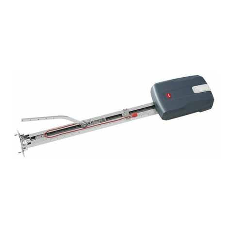
Attuatore per motorizzazione di porte sezionali residenziali ed industriali.
La compattezza e la versatilità di montaggio rendono la motorizzazione appli-
cabile in diverse modalità.
3) DATI TECNICI
Alimentazione: 230V ±10%, 50/60Hz (*)
Potenza assorbita max: 70W
Finecorsa: Elettronico ad ENCODER
MAX 18 giri Albero d’uscita
Luce di cortesia: Lampada 24V~ 25W max, E14
Temperatura di funzionamento: -15°C / +55°C
Dimensioni max anta: 20mq
Coppia max: 55Nm
Lubricazione: Grasso permanente
Manovra manuale: Sblocco meccanico a manopola
Grado di protezione: IP 40
Rumorosità: <70dBA
Peso operatore: 10 kg
Dimensioni : Vedi Fig. H
Alimentazione accessori: 24V~ (180 mA)
Collegamento lampeggiante: 24V max 25W
Fusibili Vedi Fig. D
Radioricevente Rolling-Code incorporata: frequenza 433.92MHz
(*) Tensioni speciali di alimentazione a richiesta.
Versioni trasmettitori utilizzabili:
Tutti i trasmettitori ROLLING CODE compatibili con .
4) SMONTAGGIO CARTER Fig. A
5) PREDISPOSIZIONE TUBI Fig. B
6) INSTALLAZIONE OPERATORE Fig. C
5) INGRESSO CAVI FIG. I
6) SBLOCCO MANUALE (Vedi MANUALE D’USO -FIG.Y-).
----------------------------------------------------------
7) COLLEGAMENTI
MORSETTO
DESCRIZIONE
JP2 Cablaggio trasformatore
JP10 Cablaggio motore
1-2 Ingressoantennaperschedaradioriceventeintegrata(1:CALZA.
2: SEGNALE)
3-4 Ingresso START / OPEN (N.O.)
3-5 Ingresso STOP (N.C.) Se non si utilizza lasciare il ponticello
inserito.
3-6 Ingresso FOTOCELLULA (N.C.) Se non si utilizza lasciare il pon-
ticello inserito.
3-7 Ingresso COSTA (N.C.) Se non si utilizza lasciare il ponticello
inserito.
8-9 Uscita 24 V~ per luce lampeggiante (25 W max)
10-11 Uscita 24V~ 180mA max - alimentazione fotocellule o altri
dispositivi.
12-13 Uscita 24V~ Vsafe 180mA max - alimentazione trasmettitori
fotocellule con verica.
14-15 (Contatto NO) / Uscita 1 programmabile in altezza
16-17 Ingresso APERTURA PARZIALE / CLOSE (N.O.)
1-2 (SCS-IO)
Ingresso FAULT-PHOT (NO). Ingresso per fotocellule dotate di
contatto N.O. di verica.
1-3 (SCS-IO)
Ingresso FAULT-BAR (NO). Ingresso per coste dotate di contatto
N.O. di verica.
4-5 (SCS-IO)
(Contatto NO) / Uscita 2 Programmabile in alternata
6-7 (SCS-IO)
Uscita spia cancello aperto / 2canale radio (contatto N.O.)
7.1) DISPOSITIVI DI SICUREZZA
Nota: utilizzare solamente dispositivi di sicurezza riceventi con contatto in
libero scambio.
Fig. L: Collegamento di 1 dispositivo non vericato (fotocellula o costa).
Fig. M: Collegamento di 1 dispositivo vericato (fotocellula o costa).
Fig. N: Collegamento di 2 dispositivi vericati (fotocellule o coste). Questo colle-
gamento è reso possibile solamente tramite il modulo opzionale SCS-IO.
8) REGOLAZIONI
SEQUENZA DI REGOLAZIONI CONSIGLIATA:
Regolazione dei necorsa (Fig. E)
Autoset (Fig. F)
Programmazione radiocomando (Fig. G)
Eventuali regolazioni dei parametri / logiche
8.1) MENU’ PARAMETRI
(TABELLA “A” PARAMETRI)
8.2) MENU’ LOGICHE
(TABELLA “B” LOGICHE)
8.3 MENU RADIO
Logica Descrizione
Aggiungi Tasto start
associa il tasto desiderato al comando Start
Aggiungi Tasto 2ch
associa il tasto desiderato al comando 2° canale radio
Leggi
Eettua una verica di un tasto di una ricevente, se memoriz-
zato restituisce numero della ricevente nella locazione della
memoria (da 01 a 64) e numero del tasto (T1-T2-T3 o T4).
Elimina Lista
ATTENZIONE!Rimuovecompletamentedallamemoria
della ricevente tutti i radiocomandi memorizzati.
Lettura codice ricevitore
Visualizza il codice ricevitore necessario per la clonazione
dei radiocomandi.
ON = Abilitalaprogrammazioneadistanzadelleschedetramite
untrasmettitoreWLINKprecedentementememorizzato.
Questa abilitazione rimane attiva 3 minuti dall’ultima
pressione del radiocomando W LINK.
OFF=Programmazione W LINK disabilitata.
- NOTA IMPORTANTE: CONTRASSEGNARE IL PRIMO TRASMETTITORE
MEMORIZZATO CON IL BOLLINO CHIAVE (MASTER).
Il primo trasmettitore, nel caso di programmazione manuale, assegna il CODICE
CHIAVE DEL RICEVITORE; questo codice risulta necessario per poter eettuare la
successiva clonazione dei radiotrasmettitori.
Il ricevitore di bordo incorporato Clonix dispone inoltre di alcune importanti
funzionalità avanzate:
• Clonazione del trasmettitore master (rolling-code o codice sso)
• Clonazione per sostituzione di trasmettitori già inseriti nel ricevitore
• Gestione database trasmettitori
• Gestione comunità di ricevitori
Per l’utilizzo di queste funzionalità avanzate fate riferimento alle istruzioni del
programmatore palmare universale ed alla Guida alla Programmazione CLONIX,
fornite con il dispositivo del programmatore palmare universale.
8.4 MENU LINGUA
Consente di impostare la lingua del programmatore a display.
8.5 MENU DEFAULT
Riporta la centrale ai valori preimpostati dei default.
8.6) MENU AUTOSETTAGGIO Fig. F
• Portare l’anta in posizione di chiusura
• Dare avvio ad una operazione di autosettaggio portandosi nell’apposito menu
del quadro VENERE D.
• Non appena premuto il pulsante OK viene visualizzato il messaggio “.... .... ....”,
la centrale comanda una manovra di apertura seguita da una manovra di
chiusura, durante al quale viene automaticamente settato il valore minimo
di coppia necessario al movimento dell’anta.
Durante questa fase è importante evitare l’oscuramento delle fotocellule,
nonchè l’utilizzo dei comandi START, STOP e del display.
Alterminediquestaoperazionelacentraledicomandoavràautomaticamente
impostato i valori ottimali di coppia. Vericarli ed eventualmente modicarli
come descritto in programmazione
10 - ARGO
D811627 00100_02
https://appceso.com

MANUALE PER L’INSTALLAZIONE
ATTENZIONE!! Verificare che il valore della forza d’impatto
misuratoneipuntiprevistidallanormaEN12445,siainferiore a quanto
indicato nella norma EN 12453.
Attenzione!! Durante l’autosettaggio la funzione di rileva
mentoostacolinonèattiva,l’installatoredevecontrollareilmovimento
dell’automazione ed impedire a persone o cose di avvicinarsi o sostare nel
raggio di azione dell’automazione.
8.7) MENU REGOLAZIONE FINECORSA Fig. E
Fasi della regolazione dei necorsa:
1) Posizionarsi su REG FC e confermare con OK.
2) Il display indica CLOSE, tramite i tasti SU e GIU, portare la porta nella posizione
di necorsa di chiusura. Confermare con OK, il display indica PRG.
3) Se il display lo richiede, agire sulla ghiera di regolazione: in senso antiorario
se il display indica UP, in senso orario se il display indica DOWN. Quando si
raggiunge la posizione corretta, il display indica OK. Confermare con il tasto
OK, il display indica PRG.
4) Il display indica OPEN, tramite i tasti SU e GIU, portare la porta nella posizione
di necorsa di apertura. Confermare con OK, il display indica PRG.
Se il display indica KO, signica che la regolazione non è andata a buon ne.
Le cause possono essere:
- pressione del tasto ESC prima della ne della regolazione
- corsa memorizzata troppo corta
9) MODULI OPZIONALI SCS
9.1) CONNESSIONE SERIALE MEDIANTE SCHEDA SCS1 (Fig. O)
Il quadro di comando VENERE D consente, tramite appositi ingressi e uscite
seriali (SCS1), la connessione centralizzata di più automazioni. In questo modo
è possibile, con un unico comando, eseguire l’apertura o la chiusura di tutte le
automazioni connesse.
SeguendoloschemadiFig.O,procedereallaconnessionedituttiiquadricomando
VENERE D, utilizzando esclusivamente un doppino di tipo telefonico.
Nelcasosiutilizziuncavotelefonicoconpiùcoppierisultaindispensabileutilizzare
i li della stessa coppia.
La lunghezza del cavo telefonico fra una apparecchiatura e la
successiva non deve eccedere i 250 m.
Aquestopuntoènecessariocongurareopportunamenteogniquadrocomando
VENERE D, impostando inanzitutto una centrale MASTER, che avrà il controllo di
tutte le altre, necessariamente settate come SLAVE (vedi menu logiche).
Impostare inoltre il numero di Zona (vedi menu parametri) tra 0 e 127.
Il numero di zona consente di creare dei gruppi di automazioni, ognuna
delle quali risponde al Master di Zona. Ogni zona può avere un solo Master, il
Maste0r della zona 0 controlla anche gli Slave delle altre zone.
9.2) Interfaccia con sistemi WIEGAND tramite modulo SCS-WIE.
Fare riferimento alle istruzioni del modulo SCS-WIE.
9.3) Espansione di ingressi e uscite tramite il modulo opzionale SCS-IO.
Il modulo opzionale SCS-IO permette di aggiungere 2 ingressi e 2 uscite alla
scheda VENERE-D (Fig. D).
Per attivare la connessione tra SCS-IO e VENERE-D bisogna inserire il modulo
SCS-IO nell’apposito connettore e successivamente impostare il parametro
ZONA = 129.
A questo punto le 2 schede sono sincronizzate e gli ingressi / uscite della scheda
SCS-IO sono gestiti dalla scheda VENERE-D.
TABELLA“A” MENU PARAMETRI -
Logica min. max. Default Denizione Descrizione
0 120 40 Tempo Chiusura
Automatica
Tempo di chiusura automatica [s]
1 99 75 Coppia motori apertura
Coppia apertura [%]
Imposta la sensibilità all’ostacolo durante l’apertura (1=max., 99=min.)
La funzione autoset imposta automaticamente questo parametro ad un
valore di 10%. L’utente può modicare questo parametro in base alle ne-
cessità di sensibilità all’ostacolo.
1 99 75 Coppia motori chiusura
Coppia chiusura [%]
Imposta la sensibilità all’ostacolo durante la chiusura (1=max., 99=min.)
La funzione autoset imposta automaticamente questo parametro ad un
valore di 10%. L’utente può modicare questo parametro in base alle ne-
cessità di sensibilità all’ostacolo.
10 99 99 Velocità in apertura
Velocita a regime in apertura [%]
Imposta la velocità che la porta deve raggiungere a regime in apertura,
in percentuale alla massima velocità raggiungibile dall’attuatore. L’even-
tuale modica di questo parametro sarà seguità da una manovra com-
pleta di settaggio (identicata dalla scritta “SET” sul display), durante la
quale non è attivo il riconoscimento dell’ostacolo.
10 99 99 Velocità in chiusura
Velocita a regime in chiusura [%]
Imposta la velocità che la porta deve raggiungere a regime in chiusura,
in percentuale alla massima velocità raggiungibile dall’attuatore. L’even-
tuale modica di questo parametro sarà seguita da una manovra com-
pleta di settaggio (identicata dalla scritta “SET” sul display), durante la
quale non è attivo il riconoscimento dell’ostacolo.
599 10 Spazio rallentamento Spazio rallentamento [%]
Imposta lo spazio di accostamento al necorsa. Questo spazio viene ese-
guito a velocità bassa.
10 99 40 Apertura parziale Apertura parziale [%]
Regola la percentuale di apertura parziale rispetto all’apertura totale nel
funzionamento“Apre parziale”.
0 129 0 Zona
Zona []
Imposta il numero di zona della porta inserita nella connessione seriale
per comandi centralizzati. Zona=128 Non Utilizzabile.
Zona=129 Utilizzo del modulo opzionale SCS -I0.
1 99 50 Uscita 1 programmabile
in altezza
L’uscita tra i morsetti 14-15 si attiva quando la porta supera la percentuale
di apertura impostata in questo parametro (1% = porta chiusa, 99% =
porta aperta).
1 99 50 Uscita 2 programmabile
in altezza
L’uscita tra i morsetti 4-5 del modulo opzionale SCS-IO si attiva quando la
porta supera la percentuale di apertura impostata in questo parametro
(1% = porta chiusa, 99% = porta aperta).
ARGO - 11
D811627 00100_02
https://appceso.com

MANUALE PER L’INSTALLAZIONE
TABELLA “B” MENU LOGICHE -
Logica min. max. default Denizione Descrizione
--- --- OFF Tempo Chiusura
Automatica
ON Attiva la chiusura automatica
OFF Esclude la chiusura automatica.
--- --- OFF Blocca Impulsi ON L’impulso di start non ha alcun eetto durante la fase di apertura.
OFF L’impulso di start ha eetto durante la fase di apertura.
--- --- OFF 3 Passi
ON Abilita la logica 3 passi. Un impulso di start ha i seguenti eetti:
porta chiusa: apre
in apertura: ferma ed inserisce il TCA (se congurato).
porta aperta: chiude
in chiusura:ferma e riapre
OFF Abilita logica 4 passi. Un impulso di start ha i seguenti eetti:
porta chiusa: apre
in apertura: ferma ed inserisce il TCA (se congurato)
porta aperta: chiude
in chiusura: ferma e non inserisce il tca (stop)
--- --- OFF Preallarme ON Il lampeggiante si accende circa 3 secondi prima della partenza dei motori.
OFF Il lampeggiante si accende contemporanteamente alla partenza dei motori.
--- --- OFF Uomo presente
ON Funzionamento a uomo presente in chiusura: la manovra di apertura avviene in modo
automatico, la manovra di chiusura continua nché viene mantenuta la pressione sul
tasto di comando (CLOSE).
OFF Funzionamento a impulsi (standard).
--- --- OFF Fotocellule in
apertura
ON In caso di oscuramento, esclude il funzionamento della fotocellula in apertura. In fase
di chiusura, inverte immediatamente.
OFF In caso di oscuramento, le fotocellule sono attive sia in apertura che in chiusura. Un
oscuramento della fotocellula in chiusura, inverte il moto solo dopo il disimpegno della
fotocellula.
--- --- OFF Test fotocellula
ON Attiva la verica delle fotocellule
OFF Disattiva la verica delle fotocellule
Se disabilitato (OFF) inibisce la funzione di verica delle fotocellule, consentendo la
connnessione di dispositivi non dotati di contatto supplementare verica.
--- --- OFF Test costa
ON Attiva la verica della costa
OFF Disattiva la verica della costa
Se disabilitato (OFF) inibisce la funzione di verica della costa, consentendo la conn-
nessione di dispositivi non dotati di contatto supplementare verica.
--- --- OFF Master/Slave ON Il quadro comando viene settato come Master in un collegamento centralizzato.
OFF Il quadro comando viene settato come Slave in un collegamento centralizzato.
--- --- OFF Codice Fisso ON Il ricevitore risulta congurato per il funzionamento in modalità codice sso.
OFF Il ricevitore risulta congurato per il funzionamento in modalità rolling-code.
--- --- ON Programmazione
radiocomandi
ON Abilita la memorizzazione via radio dei trasmettitori: (Fig. K)
1- Premere in sequenza il tasto nascosto (P1) e il tasto normale (T1-T2-T3-T4) di un
trasmettitore già memorizzato in modalità standard attraverso il menu radio.
2- Premere entro 10s il tasto nascosto (P1) ed il tasto normale (T1-T2-T3-T4) di un
trasmettitore da memorizzare.
La ricevente esce dalla modalità programmazione dopo 10s, entro questo tempo è
possibile inserire ulteriori nuovi trasmettitori.
Questa modalità non richiede l’accesso al quadro comando.
OFF Disabilita la memorizzazione via radio dei trasmettitori.
I trasmettitori vengono memorizzati solo utilizzando l’apposito menu Radio.
--- --- OFF
Spia cancello
aperto o
II° canale radio
ON L’uscita tra i morsetti 6 - 7 del modulo opzionale SCS-10 viene congurata come Spia
cancello aperto, il II° canale radio in questo caso comanda l’apertura pedonale.
OFF L’uscita tra i morsetti 6 - 7 del modulo opzionale SCS-10 viene congurata come II°
canale radio.
--- --- OFF Selezione
START - OPEN
ON L’ingresso tra i due morsetti 3 - 4 funziona come OPEN.
OFF L’ingresso tra i due morsetti 3 - 4 funziona come START.
--- --- OFF
Selezione
PEDONALE -
CLOSE
ON L’ingresso tra i due morsetti 16 - 17 funziona come CLOSE.
OFF L’ingresso tra i due morsetti 16 - 17 funziona come PEDONALE.
--- --- OFF Inversione del
moto
ON Inverte il moto della rotazione standard (Vedi Fig.I).
OFF Rotazione standard (Vedi Fig.I).
12 - ARGO
D811627 00100_02
https://appceso.com

N?P?K
N?P?K
N?P?K
JMEGAJMEGA
JMEGA
JMEGA
.0%
'2
$0
"#3
#,%
CQN
OK
OK
OK
OK
OK
-+
-+
-+
-+
?BBQR?PR
FGBBCL@SRRML
PCJC?QC BCQGPCB@SRRML
.0%
PC?B
CP?QC
!-"06
!
OK
$"
OK
OK
BBAF
+/-
R
See PARAMETERS MENU
See LOGIC MENU
See RADIO MENU
P?BGM
ACCESS TO MENUS
Cancel/return to main menu
Scroll up
CLB
CLB
CLB
CLB
CLB
CLB
CLB
JGLES?
BCD?SJR
?SRMQCR
Scroll down
Description
.#" partial opening input activated
120C START input activated
12-. STOP input activated
.&-2 PHOT input activated
0 SAFETY EDGE input activated
!*-1 CLOSE input activated
-.#, OPEN input activated
1SM opening limit switch activated
1SA closing limit switch activated
photocell test error
safety edge test error
1CR
#0
#0
#0
reverse due to obstacle
autoset function is running
WARNING! Obstacle detection function is not active
Logic
35.40
Set torque threshold %
Maximum motor torque %
#0
#0
#0
#0
mosfet test error
shunt test error
encoder test error
thermal cutout error
optional module communication error
(Fig. F)
LIMIT SWITCH ADJUSTMENT
Control unit software version
N. total manoeuvres (in tens)
N. manoeuvres since latest maintenance (in tens)
N. radio control devices memorised
Press the OK key
FGBBCL@SRRML
PCJC?QC BCQGPCB@SRRML
T
JQU?BH
Confirm/Switch on display
M
M
.
ENGLISH
ARGO - 13
D811627 00100_02
https://appceso.com

INSTALLATION MANUAL
WARNING! Important safety instructions. Carefully read and comply with the
WarningsbookletandInstructionbookletthatcomewiththeproductasincorrect
installationcancauseinjurytopeopleandanimalsanddamagetoproperty.They
containimportantinformationregardingsafety,installation,useandmaintenance.
Keep hold of instructions so that you can attach them to the technical le and
keep them handy for future reference.
1) GENERAL SAFETY
- The units making up the machine and its installation must meet the requi-
rements of the following European Directives: 2004/108/EEC, 2006/95/EEC,
98/37/EEC, 89/106/EEC and later amendments. For all countries outside the
EEC, it is advisable to comply with the above-mentioned standards, in addi-
tion to any national standards in force, to achieve a good level of safety.
- The Firm disclaims all responsibility resulting from improper use or any use
other than that for which the product has been designed, as indicated he-
rein, as well as for failure to apply Good Practice in the construction of entry
systems (doors, gates, etc.) and for deformation that could occur during use.
- Make sure the stated temperature range is compatible with the site in which
the automated system is due to be installed.
- Do not install the product in an explosive atmosphere.
- Disconnect the electricity supply before performing any work on the system.
Also disconnect buer batteries, if any are connected.
- Have the automated system’s mains power supply tted with a switch or om-
nipolar thermal-magnetic circuit breaker with a contact separation of at least
3.0 mm.
- Make sure that upline from the mains power supply there is a residual current
circuit breaker that trips at 0.03A.
- Make sure the earth system has been installed correctly: earth all the metal
parts belonging to the entry system (doors, gates, etc.) and all parts of the
system featuring an earth terminal.
- Installation must be carried out using safety devices and controls that meet
standard EN 12978.
- Apply all safety devices (photocells, safety edges, etc.) required to keep the
area free of crushing, dragging and shearing hazards.
- The motor cannot be installed on panels incorporating doors (unless the mo-
tor can be activated when the door is open)
- If the automated device is installed at a height of less than 2.5 m or is accessi-
ble, the electrical and mechanical parts must be suitably protected.
- Any xed controls must be installed within sight of the door but away from
moving parts. Unless the control is key operated, it must be installed at a
height of at least 1.5 m and in a place where it cannot be reached by the
public
- Apply at least one warning light (ashing light) in a visible position, and also
attach a Warning sign to the structure.
- If there are no instructions already, attach a label near the operating device,
in a permanent fashion, with information on how to operate the manual rele-
ase.
- Make sure that nothing can be crushed between the guided part and sur-
rounding xed parts during the door’s operation
- Once installation is complete, make sure the motor has the right settings and
that the safety and release systems are working properly.
- Only use original spare parts for any maintenance or repair work. The Firm
disclaims all responsibility for the correct operation and safety of the automa-
ted system if parts from other manufacturers are used.
- Do not make any modications to the automated system’s components un-
less explicitly authorized by the Firm.
- Dispose of packaging materials (plastic, cardboard, polystyrene, etc.) in accor-
dance with the provisions of the laws in force. Keep nylon bags and polystyre-
ne out of reach of children.
Warning! For connection to the mains power supply, use a multicore cable
with a cross-section of at least 4x1.5mm2of the kind provided for by the
regulations mentioned above (by way of example, type H05VV-F cable can
be used with a cross-section of 4x1.5mm2). To connect auxiliary equipment,
use wires with a cross-section of at least 1 mm2.
Have an omnipolar circuit breaker installed with a contact separation of
at least 3 mm and featuring overload protection, suitable for cutting the
automated device o from the mains.
Only use pushbuttons with a capacity of 10A-250V or more.
The cables must be held in position using an extra xing device in the prox-
imity of the terminals, e.g. with cable clamps.
Also add more clips to the limit device wires, to the transformer primary or
secondary wires, and to the wires connected to the printed circuit.
Duringinstallation,the powersupplycablemustbe stripped inorderforthe
earthing wire to be connected to the appropriate terminal, but the active
wires must be left as short as possible.The earthing wire must be the last to
stretch in the case where the cable xing device becomes loose.
WARNING: extremely low safety voltage cables must be phisically
separated from low voltage cables.
Access to the electrical compartment or to limit switches must be allowed
to skilled personnel only.
Compliancewith currentsafety rules with regardtopeople,animals and property
mustbeassuredatalltimesand,morespecically,measuresmustbetakentoavoid
risks of injury due to crushing, in the area where the pinion and rack mesh, and
any other mechanical hazards. All critical points must be protected by safety
devices in accordance with the provisions of the regulations in force.
CHECKING THE AUTOMATED DEVICE
Before the automated device is nally put into operation, perform the following
checks meticulously:
• Make sure all components are fastened securely.
• Check the correct functioning of all safety devices (limit microswitches, pho-
tocells, sensitive edges etc.).
• Make sure that the anti-crush system stops the door within the limits provided
for by the standards in force.
• Check the emergency operation control device.
•
Check the opening and closing operations with the control devices in use.
• Check the standard and customised electronic functioning logic.
USE OF THE AUTOMATED DEVICE
Since the automated device can be remote controlled via a remote control or
start button, hence with the door out of sight, it is vital that all safety devices be
checked frequently to ensure they are in perfect working order. If there is any
malfunction, take prompt action, calling in qualied personnel to do the job.
You are strongly advised to keep children well out of range of the automated
system. Depending on the type of control applied, the automated device must
be used in compliance with the installer’s instructions in order to operate without
endangering people, animals or property.
CONTROL
The purpose of using the automated device is to enable motorized door ope-
ning and closing. There are various options when it comes to the control system
(manual, remote control, access control with magnetic badge etc.) depending
on the installation’s needs and characteristics. See the relevant instructions for
the various control system options.
People due to use the automated device must be instructed how to control
and use it.
MAINTENANCE
When performing maintenance of any kind, cut o power to the system.
• Check the drive system at regular intervals.
• Check all safety devices installed for the door and drive
.
• In the event of any anomalous functioning which cannot be resolved, discon-
nect the power supply and contact a specialised technician (installer). Whilst
the automation is out of order, activate the manual release to allow manual
opening and closing.
SCRAPPING
WARNING! Employ the services of qualied personnel only. Materials must be
disposed of in accordance with the regulations in force. There are no particular
hazards or risks involved in scrapping the automated system. For the purpose
of recycling, it is best to separate dismantled parts into like materials (electrical
parts - copper - aluminium - plastic - etc.).
DISMANTLING
WARNING! Employ the services of qualied personnel only.
If the automated system is being dismantled in order to be reassembled at another
site, you are required to:
• Cut o the power and disconnect the whole external electrical system.
• See to the replacement of any components that cannot be removed or happen
to be damaged.
14 - ARGO
D811627 00100_02
https://appceso.com

INSTALLATION MANUAL
2) GENERAL INFORMATION
Actuator for motorizing residential and industrial sectional doors.
Its compact design and mounting versatility mean the drive can be applied in
dierent ways.
3) TECHNICAL SPECIFICATIONS
Power supply: 230V ±10%, 50/60Hz (*)
Max. power input: 70W
Limit switch: Electronic ENCODER model
Output shaft MAX. 18 rpm
Courtesy light: 24V bulb ~ max. 25W, E14
Operating temperature range: -15°C / +55°C
Max. door size: 20 m2
Max. torque: 55 Nm
Lubrication: Lifetime greased
Manual operation: Knob-operated mechanical release
Protection rating: IP 40
Noise level: <70dBA
Operator weight: 10 kg
Dimensions: See Fig. H
Accessories power supply: 24V~ (180 mA)
Flashing light connection: 24V max 25W
Fuses: See Fig. D
Built-in Rolling-Code radio-receiver: frequency 433.92MHz
(*) Special supply voltages to order.
Usable transmitter versions:
All ROLLING CODE transmitters compatible with .
4) REMOVING THE COVER Fig. A
5) TUBE ARRANGEMENT Fig. B
6) INSTALLING THE OPERATOR Fig. C
5) CABLE ENTRY FIG. I
6) MANUAL RELEASE (See USER GUIDE -FIG. Y-).
----------------------------------------------------------
7) WIRING
TERMINAL
DESCRIPTION
JP2
Transformer wiring
JP10
Motor wiring
1-2
Antenna input for built-in radio-receiver board (1:BRAIDING 2:
SIGNAL)
3-4
START/OPEN INPUT (N.O.)
3-5
STOP input (N.C.) If not used, leave jumper inserted
3-6
PHOTOCELL input (N.C.) If not used, leave jumper inserted
3-7
SAFETY EDGE input (N.C.) If not used, leave jumper inserted
8-9
24 V~ output for ashing light (max. 25 W)
10-11
24V~ max. 180mA output - power supply to photocells or other devices.
12-13
24V~ Vsafe max. 180mA output - power supply to transmitters
photocells with test.
14-15
(NO contact) / Output 1 height programmable
16-17
PARTIAL OPENING/CLOSE input (N.O.)
1-2 (SCS-IO)
PHOT-FAULT input (NO). Input for photocells equipped with NO
test contact.
1-3 (SCS-IO)
BAR-FAULT input (NO). Input for safety edges equipped with NO
test contact.
4-5 (SCS-IO)
(NO contact) / Output 2 Height programmable
6-7 (SCS-IO)
Gate open light/2nd radio channel output (NO contact)
7.1) SAFETY DEVICES
Note: only use receiving safety devices with free changeover contact.
Fig. L: Connection of 1 untested device (photocell or safety edge).
Fig. M: Connection of 1 tested device (photocell or safety edge).
Fig. N: Connection of 2 tested devices (photocells or safety edges). This con-
nection is made possible via the SCS-IO optional module only.
8) ADJUSTMENTS
RECOMMENDED ADJUSTMENT SEQUENCE:
Adjusting the limit switches (Fig. E)
Autoset (Fig. F)
Programming remote controls (Fig. G)
Setting of parameters/logic, where necessary
8.1) PARAMETERS MENU
(TABLE “A” PARAMETERS)
8.2) LOGIC MENU
(TABLE “B” LOGIC)
8.3 RADIO MENU
Logic Description
Add Start Key
associates the desired key with the Start command
Add 2ch Key
associates the desired key with the 2nd radio channel command
Read
Checks a key of a receiver and, if memorized, returns the
number of the receiver in the memory location (from 01 to
64) and number of the key (T1-T2-T3 or T4).
Erase List
WARNING! Erases all memorized remote controls from
the receiver’s memory.
Read receiver code
Displays receiver code required for cloning remote controls.
ON = Enables remote programming of cards via a previously me-
morizedWLINKtransmitter.Itremainsenabledfor3minutes
from the time the W LINK remote control is last pressed.
OFF=W LINK programming disabled.
- IMPORTANT NOTE: THE FIRST TRANSMITTER MEMORIZED MUST BE
IDENTIFIED BY ATTACHING THE KEY LABEL (MASTER).
In the event of manual programming, the rst transmitter assigns the RECEIVER’S
KEY CODE: this code is required to subsequently clone the radio transmitters.
The Clonix built-in on-board receiver also has a number of important advanced
features:
• Cloning of master transmitter (rolling code or xed code)
• Cloning to replace transmitters already entered in receiver
• Transmitter database management
• Receiver community management
To use these advanced features, refer to the universal handheld programmer’s
instructions and to the CLONIX Programming Guide, which come with the uni-
versal handheld programmer device.
8.4 LANGUAGE MENU
Used to set the programmer’s language on the display.
8.5 DEFAULT MENU
Restores the controller’s default factory settings.
8.6) AUTOSET MENU Fig. F
• Move the door to the closed position.
• Launch an autoset operation by going to the relevant menu on the VENERE
D panel.
• As soon as you press the OK button, the “.... .... ....” message is displayed and
the control unit commands the door to perform a full cycle (opening followed
by closing), during which the minimum torque value required for the door to
move is set automatically.
During this stage, it is important to avoid breaking the photocells’beams and
not to use the START and STOP commands or the display.
Once this operation is complete, the control unit will have automatically set
the optimum torque values. Check them and, where necessary, edit them as
described in the programming section.
WARNING: Check that the force of impact measured at the points
provided for by standard EN 12445 is lower than the value laid down
by standard EN 12453.
ARGO - 15
D811627 00100_02
https://appceso.com

INSTALLATION MANUAL
Warning!!Whiletheautosetfunctionisrunning,theobstacledetection
function is not active. Consequently, the installer must monitor the
automatedsystem’s movementsand keeppeopleandpropertyoutofrange
of the automated system.
8.7) LIMIT SWITCH ADJUSTMENT MENU Fig . E
Limit switch adjustment procedure:
1) Go to L.SW ADJ and conrm with OK.
2) The display reads CLOSE. Use the UP and DOWN keys to move the door to the
closing limit switch position. Conrm with OK. The display reads PRG.
3) Ifpromptedbythedisplay,turntheadjustmentring:anticlockwiseifthedisplay
reads UP; clockwise if the display reads DOWN. Once you have reached the
correct position, the display reads OK. Conrm with the OK key. The display
reads PRG.
4) The display reads OPEN. Use the UP and DOWN keys to move the door to the
opening limit switch position. Conrm with OK. The display reads PRG.
If the display reads KO, it means adjustment was not successful.
This may be caused by:
- the ESC key being pressed before adjustment was completed
- stored travel being too short
9) SCS OPTIONAL MODULES
9.1) SERIAL CONNECTION VIA SCS1 CARD (Fig. O)
The VENERE D control panel’s special serial inputs and outputs (SCS1) make the
centralized connection of a number of automated devices possible. That way,
all the automated devices connected can be opened or closed with a single
command.
Connect all VENERE D control panels using twisted pair cabling only, proceeding
as shown in the diagram in Fig. O.
When using a telephone cable with more than one pair, it is essential to use wires
from the same pair.
The length of the telephone cable between one unit and the next must not
be greater than 250 m.
At this point, eachVENERE D control panel needs to be congured appropriately,
starting by entering a MASTER control panel that will have control over all the
others, which therefore have to be set as SLAVE units (see logic menu).
Also set the Zone number (see parameters menu) in the range 0 to 127.
Thezonenumberallowsyoutocreategroupsofautomateddevices,eachofwhich
answers to the Zone Master. Each zone can have only one Master: the Master of
zone 0 also controls the Slaves of the other zones.
9.2) Interface with WIEGAND systems via SCS-WIE module.
Refer to the SCS-WIE module’s instructions.
9.3) Expanding inputs and outputs via the SCS-IO optional module.
The SCS-IO optional module can be used to add 2 inputs and 2 outputs to the
VENERE-D board (Fig. D).
To activate the connection between SCS-IO and VENERE-D, you need to plug the
SCS-IO module into the relevant connector and then set the ZONE parameter
to 129.
Atthispoint,the2 boardsaresynchronizedandtheSCS-IOboard’sinputs/outputs
are managed by the VENERE-D board.
TABLE“A” PARAMETERS MENU -
Logic min. max. default Denition Description
0 120 40 Automatic Closing Time Automatic closing time [s]
1 99 75 Opening motor torque
Opening torque [%]
Sets sensitivity to obstacles during opening (1=max., 99=min.) The auto-
set feature sets this parameter automatically to a value of 10%. The user
can edit this parameter based on how sensitive the door needs to be to
obstacles.
1 99 75 Closing motor torque
Closing torque [%]
Sets sensitivity to obstacles during closing (1=max., 99=min.) The auto-
set feature sets this parameter automatically to a value of 10%. The user
can edit this parameter based on how sensitive the door needs to be to
obstacles.
10 99 99 Speed during opening
Running speed during opening [%]
Sets the running speed that the door must reach during opening, as a
percentage of the maximum speed the actuator can reach. Should this
parameter be edited, it will be followed by a complete opening/closing
cycle for setting purposes (reported by the message “SET” appearing on
the display), during which obstacle detection is not enabled.
10 99 99 Speed during closing
Running speed during closing [%]
Sets the running speed that the door must reach during closing, as a
percentage of the maximum speed the actuator can reach. Should this
parameter be edited, it will be followed by a complete opening/closing
cycle for setting purposes (reported by the message “SET” appearing on
the display), during which obstacle detection is not enabled.
599 10 Slow-down distance Slow-down distance [%]
Sets the approach distance to reach the travel limit. This distance is tra-
velled at low speed.
10 99 40 Partial opening Partial opening [%]
Adjusts partial opening percentage compared to total opening in “Par-
tial open”mode.
0 129 0 Zone
Zone []
Sets the zone number of the door included in the serial connection for
commands via central controllers. Zona=128 not used.
Zone=129 Use of optional SCS -I0 module.
1 99 50 Output 1 height programmable The output between terminals 14-15 is activated when the door exceeds
the opening percentage set with this parameter (1% = door closed, 99%
= door open).
1 99 50 Output 2 height programmable
The output between terminals 4-5 on the SCS-IO optional module is
activated when the door exceeds the opening percentage set with this
parameter (1% = door closed, 99% = door open).
16 - ARGO
D811627 00100_02
https://appceso.com

INSTALLATION MANUAL
TABLE“B” LOGIC MENU -
Logic min. max. default Denition Description
--- --- OFF Automatic
Closing Time
ON Switches automatic closing on
OFF Switches automatic closing o
--- --- OFF Block Pulses ON The start pulse has no eect during opening.
OFF The start pulse has eect during opening.
--- --- OFF 3 Step
ON Switches to 3-step logic. A start pulse has the following eects:
door closed: opens
during opening: stops and switches on TCA (if congured).
door open: closes
during closing: stops and opens again
OFF Switches to 4-step logic. A start pulse has the following eects:
door closed: opens
during opening: stops and switches on TCA (if congured)
door open: closes
during closing: stops and does not switch on tca (stop)
--- --- OFF Pre-alarm ON The ashing light comes on approx. 3 seconds before the motors start.
OFF The ashing light comes on at the same time as the motors start
--- --- OFF Deadman
ON Deadman mode during closing: opening operation performed in automatic mode;
closing operation continues as long as the control key is held down. (CLOSE).
OFF Pulse operation (standard)
--- --- OFF Photocells
during opening
ON: Whenbeamis broken,operationofthephotocellisswitchedoduringopening.During
closing, movement is reversed immediately.
OFF: When beam is broken, photocells are active during both opening and closing. When
beam is broken during closing, movement is reversed only once the photocell is clea-
red.
--- --- OFF Photocell test
ON Switches photocell testing on
OFF Switches photocell testing o
If disabled (OFF), it inhibits the photocell testing function, enabling connection of
devices not equipped with supplementary test contacts.
--- --- OFF Safety edge
testing
ON Switches safety edge testing on
OFF Switches safety edge testing o
If disabled (OFF), it inhibits the safety edge testing function, enabling connection of
devices not equipped with supplementary test contacts
--- --- OFF Master/Slave ON Control panel is set up as the Master unit in a centralized connection system.
OFF Control panel is set up as a Slave unit in a centralized connection system.
--- --- OFF Fixed code ON Receiver is congured for operation in xed-code mode.
OFF Receiver is congured for operation in rolling-code mode.
--- --- ON Remote control
programming
ON Enables wireless memorizing of transmitters: (Fig. K)
1- Press in sequence the hidden key (P1) and normal key (T1-T2-T3-T4) of a transmitter
that has already been memorized in standard mode via the radio menu.
2- Press within 10 sec. the hidden key (P1) and normal key (T1-T2-T3-T4) of a transmitter
to be memorized.
The receiver exits programming mode after 10 sec.: you can use this time to enter other
new transmitters.
This mode does not require access to the control panel.
OFF Disables wireless memorizing of transmitters.
Transmitters are memorized only using the relevant Radio menu.
--- --- OFF Gate open light or
2nd radio channel
ON The output between terminals 6-7 on the optional SCS-10 module is set as Gate
open light: in this case, the 2nd radio channel controls pedestrian opening.
OFF The output between terminals 6-7 on the optional SCS-10 module is set as 2nd radio
channel
--- --- OFF Selection
START - OPEN
ON Input between terminals 3-4 works as OPEN.
OFF Input between terminals 3-4 works as START
--- --- OFF
Selection
PEDESTRIAN -
CLOSE
ON Input between terminals 16-17 works as CLOSE.
OFF Input between terminals 16-17 works as PEDESTRIAN
--- --- OFF Reversing motion ON Reverses motion of standard rotation (See Fig.I).
OFF Standard rotation (See Fig.I).
ARGO - 17
D811627 00100_02
https://appceso.com

N?P?K
N?P?K
N?P?K
JMEGAJMEGA
JMEGA
JMEGA
.0%
'2
$0
"#3
#,%
CQN
OK
OK
OK
OK
OK
-+
-+
-+
-+
?BHQR?PR
RMSAFCA?AFCC PCJ?AFCP RMSAFCBCQGPCC
.0%
JGPC
CDD?ACP
!-"06
!
OK
$"
OK
OK
?BHAF
+/-
R
Voir MENU PARAMÈTRES
Voir MENU LOGIQUES
Voir MENU RADIO
P?BGM
ACCES AUX MENUS
Annuler/revenir au menu principal
Confirmation/Allumage afficheur
Monter
DGL
DGL
DGL
DGL
DGL
DGL
DGL
J?LESC
BCD?SJR
?SRMQCR
Descendre
Description
.#" activation entrée ouverture partielle
120C activation entrée START
12-. activation entrée STOP
.&-2 activation entrée PHOT
0 activation entrée COSTA
!*-1 activation entrée CLOSE
-.#, activation entrée OPEN
1SM activation fin de course ouverture
1SA activation fin de course fermeture
erreur test photocellule
QCR
#0
#0
#0
inversion pour obstacle
réglage automatique
Attention! Fonction de détection des obstacles n’étant pas active
Logique
35.40
Seuil de couple réglée %
Couple maximal moteur %
Version logiciel de la centrale
N° manoeuvres totales (en dizaines)
N° manoeuvres depuis le dernier entretien (en dizaines)
N° commandes radio mémorisées
#0
#0
#0
#0
erreur test barre palpense
erreur test mosfet
erreur test shunt
erreur test encodeur
erreur thermique
erreur communication avec module en option
RÉGLAGE FIN DE COURSE
(Fig. F)
Appuyer sur la touche OK
RMSAFCA?AFCC PCJ?AFCP RMSAFCBCQGPCC
T
PCEJDA
M
M
.
18 - ARGO
D811627 00100_02
https://appceso.com

MANUEL D’INSTALLATION
ATTENTION! Consignes de sécurité importantes. Lire et suivre attentivement la
brochure Avertissement et le livret d’instructions fournis avec le produit sachant
qu’uneinstallationincorrectepeutprovoquerdesdommagesauxpersonnes,aux
animauxouauxchoses. Elles fournissent desindicationsimportantesconcernant
la sécurité, l’installation, l’utilisation et l’entretien. Ranger les instructions avec le
manuel technique an de pouvoir les consulter par la suite.
1) SÉCURITÉ GÉNÉRALE
- Les éléments qui composent l’appareil doivent être conformes aux Directives
Européennes suivantes : 2004/108/CEE, 2006/95/CEE,98/37/CEE, 89/106/CEE
et modications successives. Pour les pays n’appartenant pas à la CEE, il est
conseillé de respecter également les normes citées, outre les règlements na-
tionaux en vigueur, an de garantir un bon niveau de sécurité.
- L’entreprise décline toute responsabilité quant à l’utilisation incorrecte ou dif-
férente de celle indiquée dans la présente documentation et pour laquelle l’ap-
pareil est destiné. Elle décline également toute responsabilité quant à l’inob-
servation de la bonne technique dans la construction des fermetures (portes,
portails, etc.) et aux déformations pouvant se vérier pendant l’utilisation.
- Vérier que l’intervalle de température déclaré est compatible avec le lieu
destiné à l’installation de l’automatisation.
- Ne pas installer l’appareil dans une atmosphère explosive.
- Avant d’eectuer une quelconque intervention sur l’installation, la mettre
hors tension. Déconnecter également les batteries tampon éventuellement
présentes.
- Monter sur le réseau d’alimentation de l’automatisation un interrupteur ou
un magnétothermique unipolaire ayant une distance d’ouverture des con-
tacts supérieure ou égale à 3,0 mm.
- Vérier s’il y a, en amont du réseau d’alimentation, un interrupteur diérentiel
ayant un seuil d’intervention de 0,03 A.
- Vérier si l’installation de mise à la terre est correctement réalisée: connecter
toutes les parties métalliques de la fermeture (portes, portails, etc..) et tous
les composants de l’installation munis de borne de terre.
- L’installation doit être équipée de dispositifs de sécurité et de commandes
conformes à la norme EN 12978.
- Appliquer tous les dispositifs de sécurité (photocellules, linteaux sensibles,
etc..) nécessaires pour protéger la zone des risques d’écrasement, d’entraîne-
ment ou de cisaillement.
- Le moteur ne peut pas être installé sur des vantaux qui intègrent des portes
(à moins que le moteur soit activable lorsque la porte est ouverte).
- Si l’automatisation est installée à une hauteur inférieure à 2,5 m ou si elle est
accessible, il faut nécessairement garantir un degré de protection adapté des
parties électriques et mécaniques.
- Installer toute commande xe à proximité de la porte mais loin des parties
mobiles. Excepté si elle est à clé, la commande doit être installée à une hau-
teur de minimum 1,5 m et ne doit pas être accessible au public.
- Appliquer au moins un dispositif de signalement lumineux (clignotant) visi-
ble, xer également un panneau d’attention à la structure.
- Si aucune indication n’est présente, xer de manière permanente une éti-
quette relative au fonctionnement du déclencheur manuel et la placer près
de l’organe de manoeuvre.
- Eviter qu’il n’y ait pendant la manœuvre un écrasement entre la partie guidée
et les parties xes voisines.
- Après avoir eectué l’installation, s’assurer que le réglage du moteur est cor-
rectement réglé et que les systèmes de protection et de déblocage fonction-
nement correctement.
- Utiliser exclusivement des pièces détachées d’origine pour les opérations
d’entretien ou les réparations. Le Fabricant décline toute responsabilité quant
à la sécurité et au bon fonctionnement de l’automatisation si des composants
d’autres fabricants sont utilisés.
- Ne modier d’aucune façon les composants de l’automatisation sans l’autori-
sation expresse du Fabricant.
- Se débarrasser du matériel d’emballage (plastique, carton, polystyrène, etc.)
conformément aux normes en vigueur. Ne pas laisser les sachets en plastique
et la mousse de polystyrène à la portée des enfants.
Attention! Pour le branchement au réseau, utiliser un câble multipolaire
de section minimale 4x1,5mm2et du type prévu par les normes citées
précédemment (à titre d’exemple, le câble peut être du type H05 VV-F avec
une section 4x1,5mm2). Pour le branchement des auxiliaires, utiliser des
conducteurs avec une section minimale de1 mm2.
Prévoir un interrupteur omnipolaire avec une ouverture des contacts de
minimum 3 mm équipé d’une protection contre les surcharges, visant à
sectionner l’automatisation du réseau.
Utiliser exclusivement des boutons avec une portée supérieure ou égale
à 10A-250V.
Les conducteurs doivent être bloqués par une xation supplémentaire à
proximité des bornes, par exemple au moyen de colliers.
Ajouter également des colliers supplémentaires aux conducteurs des ns
de course, aux conducteurs du primaire et du secondaire du transformateur
et aux conducteurs branchés au circuit imprimé.
Le câble d’alimentation doit être dénudé pendant l’installation de façon à
permettre le branchement du conducteur de terre à la borne appropriée
en laissant cependant les conducteurs actifs les plus courts possible. Le
conducteur de terre doit être le dernier à se tendre en cas de desserrage du
dispositif de xation du câble.
ATTENTION: les conducteurs alimentés à très basse tension de sécurité
doivent être physiquement séparés des conducteurs à basse tension.
Garantir le respect des normes en vigueur en matière de personnes, animaux
et choses. Eviter les risques d’accidents liés à un écrasement, dans la zone d’en-
grènement pignon - crémaillère ainsi que les autres risques mécaniques. Tous
les points critiques devront être protégés par des dispositifs de sécurité
conformément aux normes en vigueur.
VÉRIFICATION DE L’AUTOMATISATION
Vérier scrupuleusement ce qui suit avant de rendre l’automatisation déniti-
vement opérationnelle :
• Vérier que tous les composants sont solidement xés.
• Vérier le bon fonctionnement de tous les dispositifs de sécurité (micro-n
de course, cellules photoélectriques, barres palpeuses etc.).
• Vérier que le système anti-écrasement arrête la porte dans les limites prévues
par les normes en vigueur.
• Vérier la commande de la manœuvre d’urgence.
• Vérier l’opération d’ouverture et de fermeture avec les dispositifs de com-
mande appliqués.
•
Vérier la logique électronique de fonctionnement normale et personnalisée
.
UTILISATION DE L’AUTOMATION
Etant donnée que l’automation peut être commandée à distance par radiocom-
mande ou bouton de start, et donc hors de vue, il est indispensable de contrôler
souvent le fonctionnement parfait de tous les dispositifs de sécurité. Pour toute
anomalie de fonctionnement, il faut intervenir rapidement à l’aide aussi de per-
sonnel qualié.
Il est recommandé de tenir les enfants loin du rayon d’action de l’automation.
Selon le type de commande appliquée, l’utilisation de l’automatisation doit ob-
server ce qui est indiqué par l’installateur an d’opérer en toute sécurité vis-à -vis
des personnes, des animaux et des choses.
COMMANDE
L’utilisation de l’automation permet l’ouverture et la fermeture de la porte de
façon motorisée. La commande peut être de type diérent (manuel, avec radio-
commande, contrôle des accès par carte magnétique etc.) selon les besoins et
les caractéristiques de l’installation. Pour les diérents systèmes de commande,
voir les instructions correspondantes. Les utilisateurs de l’automation doivent
être formés sur la commande et l’utilisation.
ENTRETIEN
Pour toute opération d’entretien, couper l’alimentation au système.
• Vérier périodiquement le système de transmission du mouvement.
• Vérier tous les dispositifs de sécurité de la porte et de la motorisation
.
• Pourtouteanomaliedefonctionnementnonrésolue,couperl’alimentationau
systèmeets’adresseràdupersonnelqualié(installateur).Pendant la période
de hors service, activer le déblocage manuel pour permettre l’ouverture et la
fermeture manuelle.
DÉMOLITION
ATTENTION!Nefaireappelqu’àdupersonnelqualié.L’éliminationdesmatériaux
doit être faite conformément aux normes en vigueur. En cas de démolition de
l’automatisation, il n’existe pas de dangers particuliers ou de risques dérivant de
l’automatisation en question. En cas de récupération des matériaux, les séparer
par type (parties électriques - cuivre - aluminium - plastique - etc.).
DEMONTAGE
ATTENTION! S’adresser exclusivement à du personnel qualié.
Si la motorisation doit être démontée et remontée ailleurs, il faut:
• Couper l’alimentation et débrancher toute l’installation électrique exté-
rieure.
• Si des composants ne peuvent pas être enlevés ou sont endommagés, il
faudra les remplacer.
FRANÇAIS
ARGO - 19
D811627 00100_02
https://appceso.com

MANUEL D’INSTALLATION
2) GÉNÉRALITÉS
Actionneur pour motorisation de portes résidentielles et industrielles.
La compacité et la versatilité de montage permettent d’appliquer diérents
modes de motorisation.
3) CARACTÉRISTIQUES TECHNIQUES
Alimentation : 230V ±10%, 50/60Hz (*)
Puissance max. absorbée: 70W
Fin de course : Electronique à ENCODEUR
MAX 18 tours arbre de sortie
Lumière de courtoisie: Lampe 24V~ 25W max, E14
Température de fonctionnement: -15°C / +55°C
Dimensions max. vantail: 20 m2
Couple max.: 55 Nm
Lubrication: Graisse permanente
Manœuvre manuelle: Déblocage mécanique à poignée
Degré de protection: IP 40
Bruit: <70dBA
Poids opérateur: 10 kg
Dimensions: Voir Fig. H
Alimentation des accessoires: 24V~ (180 mA)
Branchement clignotant: 24V max 25W
Fusibles: Voir Fig. D
Récepteur radio rolling code intégré: Fréquence 433,92MHz
(*) Tensions d’alimentation spéciales sur demande.
Versions des transmetteurs utilisables :
Tous les transmetteurs ROLLING CODE compatibles .
4) DÉMONTAGE DU CARTER Fig. A
5) INSTALLATION DES TUBES Fig. B
6) INSTALLATION OPÉRATEUR Fig. C
5) ENTRÉE CÂBLES FIG. I
6) DÉBLOCAGE MANUEL (Voir MANUEL D’UTILISATION -FIG.Y-).
----------------------------------------------------------
7) BRANCHEMENTS
BORNE
DESCRIPTION
JP2 câblage transformateur
JP10 câblage moteur
1-2 Entrée antenne pour che radiorécepteur
intégrée (1:TRESSE. 2: SIGNAL)
3-4 Entrée START / OPEN (N.O.)
3-5 Entrée STOP (N.C.) Si elle n’est pas utilisée, laisser le pontet
inséré.
3-6 Entrée PHOTOCELLULE (N.C.) Si elle n’est pas utilisée, laisser
le pontet inséré.
3-7
Entrée LINTEAU (N.C.) Si elle n’est pas utilisée, laisser le pontet inséré.
8-9 Sortie 24 V~ pour lumière clignotante (25 W max)
10-11 Sortie 24V~ 180mA max - alimentation photocellules ou autres
dispositifs.
12-13 Sortie 24V~ Vsafe 180mA max - alimentation transmetteurs
photocellules avec vérication.
14-15 (Contact NO) / Sortie 1 programmable en hauteur
16-17 Entrée OUVERTURE PARTIELLE / CLOSE (N.O.)
1-2 (SCS-IO)
Entrée FAULT-PHOT (NO). Entrée pour photocellules équipées
de contact N.O. de vérication
1-3 (SCS-IO)
EntréeFAULT-BAR(NO).Entréepourlinteauxéquipésde contact
de contact N.O. de vérication
4-5 (SCS-IO)
(Contact NO) / Sortie 2 programmable en hauteur
6-7 (SCS-IO)
Sortie voyant portail ouvert/ 2 canal radio (contact NO)
7.1) DISPOSITIFS DE SÉCURITÉ
Remarque: utiliser uniquement les dispositifs de sécurité récepteurs avec
contact en libre échange.
Fig. L: Branchement de 1 dispositif non vérié (photocellule ou linteau).
Fig. M: Branchement de 1 dispositif vérié (photocellule ou linteau).
Fig. N:
Branchementde2dispositifsvériés(photocellulesoulinteaux).Cebranchement
est rendu possible uniquement à travers le module en option SCS-IO.
8) RÉGLAGES
SÉQUENCE DE RÉGLAGES CONSEILLÉE:
Réglage des ns de course (Fig. E)
Réglage automatique (Autoset) (Fig. F)
Programmation de la radiocommande (Fig. G)
Réglages éventuels des paramètres / logiques
8.1) MENU PARAMÈTRES
(TABLEAU “A” PARAMÈTRES)
8.2) MENU LOGIQUES
(TABLEAU “B” LOGIQUES)
8.3 MENU RADIO
Logique Description
Ajouter Touche Start
associe la touche voulue à la commande Start
Ajouter Touche 2ch
associe la touche voulue à la commande 2° canal radio
Lire
Vérieunetouched’unrécepteur,sielleestmémorisée,restitue
le numéro du récepteur dans l’emplacement de la mémoire
(de 01 à 64) et un numéro de touche (T1-T2-T3-T4)
Eliminer Liste
ATTENTION! Elimine complètement de la mémoire du
récepteur toutes les radiocommandes mémorisées.
Lecture code récepteur
Ache le code récepteur nécessaire pour la radiocommande.
ON= Active la programmation à distance des ches à travers
un transmetteur W LINK précédemment mémorisé.
Cette activation reste active 3 minutes à compter de la
dernière pression de la radiocommande W LINK.
OFF= Programmation W LINK désactivée.
- REMARQUEIMPORTANTE:MARQUERLEPREMIERÉMETTEURMÉMORISÉ
AVEC LE TIMBRE CLÉ (MASTER).
En programmation manuelle, le premier émetteur attribue le CODE CLÉ DU
RÉCEPTEUR; ce code est nécessaire pour accomplir ensuite le clonage des
émetteurs radio.
Le récepteur de bord intégré Clonix dispose également de quelques fonction-
nalités avancées importantes:
• Clonage du transmetteur master (rolling code ou code xe)
• Clonage par substitution de transmetteurs déjà insérés dans le récepteur
• Gestion base de données transmetteurs
• Gestion communauté de récepteurs
Pour l’utilisation de ces fonctionnalités avancées, se référer aux instructions du
programmateur palmaire universel et au guide à la programmation CLONIX,
fournies avec le dispositif du programmateur palmaire universel.
8.4 MENU LANGUE
Il permet de régler la langue du programmateur à acheur.
8.5 MENU DEFAULT
Il reporte la centrale aux valeurs réglées par défaut.
8.6) MENU RÉGLAGE AUTO Fig. F
• Mettre le vantail en position de fermeture
• Démarrer une opération de réglage automatique en allant dans le menu de
la centrale VENERE D.
• Après avoir appuyé sur la touche OK le message “ ...... .... …” s’ache, la centrale
commandeunemanoeuvred’ouverturesuivied’unemanœuvredefermeture,
pendantlaquellelavaleurminimumdecouplenécessairepourle mouvement
du vantail est automatiquement réglée.
Pendant cette phase, il est important d’éviter d’obscurcir les photocellules et
d’utiliser les commandes START, STOP et l’acheur.
Autermedecetteopération,lacentraledecommandeauraautomatiquement
conguré les valeurs de couple optimales. Les vérier et les modier, le cas
échéant, comme décrit dans la programmation.
ATTENTION : vérier si la valeur de la force d’impact mesurée dans les
points prévus par la norme EN12445 est inférieure à celle indiquée
dans la norme EN 12453.
20 - ARGO
D811627 00100_02
https://appceso.com
Other manuals for ARGO
3
Table of contents
Languages:
Other BFT Door Opening System manuals

BFT
BFT OBERON TRI A2000 INV User manual

BFT
BFT CLONIX1 User manual

BFT
BFT VISTA SW 260 SXL User manual

BFT
BFT VIRGO User manual

BFT
BFT KIT P.B. BL-SMALL XTREME 35 User manual

BFT
BFT SUB EL User manual

BFT
BFT PEGASO B CJA 6 25 L01 User manual

BFT
BFT SPC User manual

BFT
BFT VIRGO User manual

BFT
BFT BRCT User manual