3
Les barrières ne sont pas des protections primaires.
Pour une meilleure sûreté, utiliser toujours une protection périmétrique
(contacts magnétiques).
Note: dans le cas d’installation, exposée aux intempéries, mettre du silicone
sur le capuchon supérieur et positionner le terminal de sortie sur la partie
inférieure (6)
*
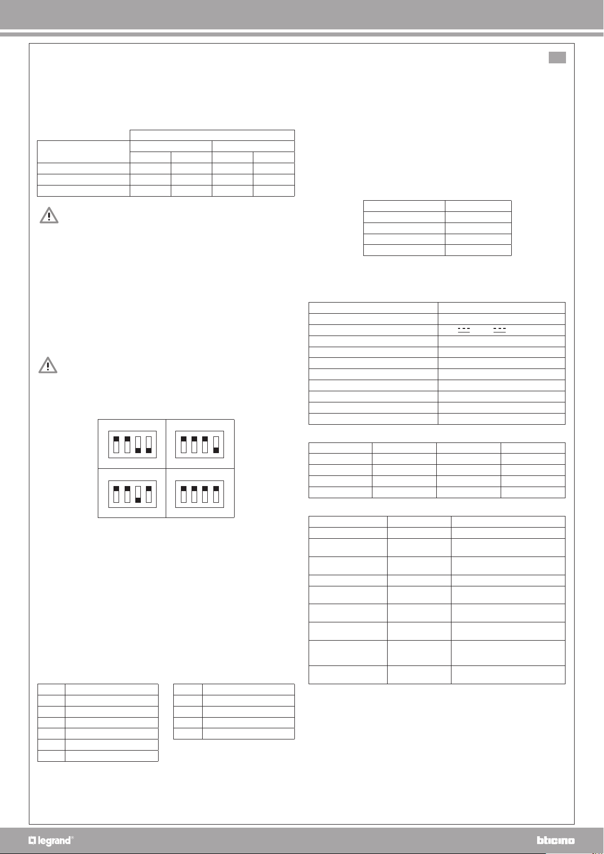
1234 1234
1234 1234
OR 100ms OR 200ms
AND 100ms AND 200ms
default
*
9. Caractéristiques techniques
Données dimensionnelles
10. Dépannage
(*) Seulement en modalité OR.
FR
Barrière à rayons infrarouges actifs
1. Fonctionnement
Le dispositif est constitué de deux colonnes, une a la fonction de transmetteur (TX),
l’autre de récepteur (RX). Les deux sont dotées de microprocesseur pour la gestion de
l’alarme et la synchronisation des rayons IR. Dans le tableau suivant il est indiqué le
temps de déclenchement de l’alarme par apport aux rayons interrompus:
OR: alarme avec interruption d’au moins un rayon,
meilleure sensibilité.
AND: alarme avec interruption d’au moins deux rayons,
moindre sensibilité.
ALARME APRES
RAYONS INTERROMPUS OR AND
100 200 100 200
1 seul 2 sec. 2 sec.
2 non contigus 1 sec. 1 sec. 1 sec. 1 sec.
2 contigus ou tous 100ms 200ms 100ms 200ms
1.1 Anti-insectes
Pour les installations dont la distance entre RX et TX est supérieure à 1 m,
l’obscurcissement d’un seul rayon, s’il se produit directement sur unes des barrières
(par exemple à cause de la présence d’un insecte), ne provoque pas d’alarme. En
revanche l’alarme est immédiate si d’autres rayons sont interrompus.
2. Installation
Les deux colonnes doivent être montées:
- L’une devant l’autre (1)
- Du même côté (les deux barrettes de connexion situées sur la partie supérieur ou
inférieur) (2)
- À une hauteur qui se rapproche le plus possible du terrain ou de la base de la fenêtre (3)
- Sans obstacles fixes ou meubles qui interrompent les rayons (4)
- De façon à ce que le récepteur RX ne soit pas directement exposé aux rayons du soleil (5)
- De façon à ce que le récepteur ne soit pas non plus directement ou par réflexion exposé
aux rayons d’autres émetteurs (9a, 9b)
3. Configuration
Les barrières sont vendues configurées pour un fonctionnement en mode «AND»
(délais d’alarme de 200ms). Pour modifier cette configuration, ce reporter au tableau
ci-dessous et à l’illustration (8).
4. Fixation
Chaque colonne est composé de:
- profilé en aluminium
- terminale supérieur (base + couvercle + vis)
- terminale inférieur (base + couvercle + vis)
- 4 vis + 4 chevilles pour la fixation au mur
1. Fixer la base du terminal inférieur (7a) à la hauteur désirée.
2. Plaquer au mur le profilé avec la base supérieure emboîtée sur celui-ci.
3. Tracer le premier point de fixation horizontal supérieur (7b).
Note: pour tracer le second point de fixation vertical, il est nécessaire de retirer le
profilé (7c).
4. Une fois les deux bases fixées, emboîté le profilé dans la base inférieure en faisant
attention de bloquer le circuit dans les arrêts et emboîté la partie supérieur sur ça
base (7d).
5. Fixer les deux couvercles (7e).
5. Connexion
Le câble peut passer par le mur ou en apparent, dans ce cas il sera nécessaire de
rompre les passages de câbles prédécoupés.
Les borniers sont débrochables facilitant ainsi le câblage.
MS1 RÉCEPTEUR (RX)
1 +13,8V
2 GND
3 PT0 Autoprotection C
4 PT1 Autoprotection N.C.
5 ALL0 Alarme C
6 ALL1 Alarme N.C.
MS1 TRANSMETTEUR (TX)
1 +13,8V
2 GND
3 PT0 Autoprotection C
4 PT1 Autoprotection N.C.
(voir schémas)
6. Liaison entre le système anti-vol et l’installation My Home
Les barrières IR viennent s’intégrées dans le système My Home par le
biais d’interfaces de contacts. Ces interfaces permettent la gestion de
l’alimentation et les alarmes détectées des barrières IR.
Si l’absorption maximum de l’installation le permet, il est possible de raccorder une
ou plusieurs barrières 3518/50 ou 3518 sur une interface contact (une interface par
barrière) voir figure 11a.
7. Alignement
Avant de refermer le couvercle du terminal côté connexion :
- Insérer le shunt JP10 en position 1-2 (basse puissance) sur le dispositif ÉMETTEUR TX.
1-2 (basse puissance) pour une distance inférieure à 3 mètres
2-3 (haute puissance) pour une distance supérieur 3 mètres
- Alimenter la barrière et appuyer un instant sur la touche «reset» située sur le dispositif
RÉCEPTEUR RX afin d’activer la procédure du «test d’alignement», en veillant à ne pas
interrompre les faisceaux.
- Après environ 8 secondes, on obtient le résultat du test et la led de l’alarme clignote.
Le nombre de clignotements indique la qualité de l’alignement.
- Fermer les couvercles.
Nb de clignotements Alignement
1 Excellent
2 Bon
3 Suffisant
4 Insuffisant
8. Anti-arrachage :
La barrière est dotée d’une auto-protection anti-ouverture et anti-arrachage sur le
terminal côté barrettes de connexion.
Portée Max. haute puissance 12m intérieur - 6m extérieur
Portée Max. basse puissance 3m intérieur / extérieur
Alimentation 12V +/- 2V
Consommation (Tx+Rx) 50 mA max
Type de signal émis IR Impulsion
Longueur d’onde = 950 nm
Synchronisation Automatique (sans fil)
Sortie auto-protection Anti-ouverture et anti-arrachage
Sortie alarme Relais contacts sec
Degré de protection IP44
Température de fonctionnement de –25C à +55C
Modèl L (m) l (mm) P (mm)
3518/50 0,58 28 25
3518 1,08 28 25
3518/150 1,58 28 25
3519 2,08 28 25
Défaut Cause possible Solution possible
Led toujours allumée TX non alimenté Vérifier l’alimentation
Led toujours allumée TX en panne Ré-alimenter ou éventuellement le
remplacer
Led toujours allumée Faisceaux
interrompus Vérifier la présence d’obstacles
Led toujours éteinte RX non alimenté Vérifier l’alimentation
Led toujours éteinte RX en panne Ré-alimenter ou éventuellement le
remplacer
Fausse alarme Barrière non
alignée Vérifier l’alignement et la puissance
(JP10)
Fausse alarme Faisceaux
assombris Vérifier la présence d’obstacles
Fausse alarme Proximité d’autres
barrières
Vérifier le positionnement et
mettre toutes les barrières en base
puissance
Pas d’alarme 2s (*) Obscurcissement
(voir. par.1.1) Pour déclencher l’alarme
interrompre le faisceau du milieu