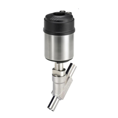
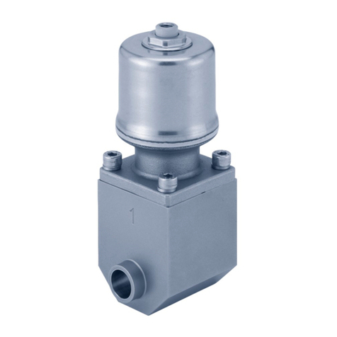
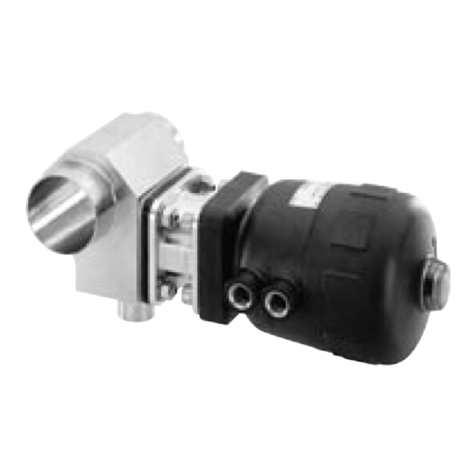
Burkert 2060 User manual

Operating Instructions
Bedienungsanleitung
Manuel d‘utilisation
Type 2060
2/2-way angle seat valve
2/2-Wege-Schrägsitzventil
Vanne à siège incliné 2/2 voies

We reserve the right to make technical changes without notice.
Technische Änderungen vorbehalten.
Sous réserve de modifications techniques.
© Bürkert Werke GmbH & Co. KG, 2016 - 2022
Operating Instructions 2208/04_EUeu_00810532 / Original DE

3
1 OPERATING INSTRUCTIONS ................................................................4
1.1 Definition of the term "device" ................................................ 4
1.2 Symbols ....................................................................................... 4
2 INTENDED USE .............................................................................................5
3 BASIC SAFETY INSTRUCTIONS ..........................................................5
4 GENERAL NOTES.........................................................................................6
4.1 Contact addresses ...................................................................6
4.2 Warranty ...................................................................................... 6
4.3 Information on the Internet ...................................................... 6
5 PRODUCT DESCRIPTION ........................................................................7
5.1 Design ..........................................................................................7
5.2 Application range ...................................................................... 7
5.3 Properties ....................................................................................7
5.4 Function ....................................................................................... 8
6 TECHNICAL DATA ........................................................................................9
6.1 Conformity ................................................................................... 9
6.2 Standards .................................................................................... 9
6.3 Type label ..................................................................................10
6.4 Conversion of actuator sizes ..........................................................10
6.5 Operating conditions ..............................................................11
6.6 General technical data ...........................................................15
7 INSTALLATION ............................................................................................16
7.1 Preparatory work .....................................................................16
7.2 Removing actuator from the valve body .............................16
7.3 Installing valve body ................................................................17
7.4 Install actuator (welded connection) ...................................17
7.5 Mount accessories ..................................................................18
7.6 Turning actuator .......................................................................18
7.7 Pneumatic connection ............................................................19
8 DISASSEMBLY ............................................................................................ 20
9 MAINTENANCE ........................................................................................... 20
9.1 Maintenance .............................................................................20
9.2 Replacing spare parts ............................................................21
10 FAULTS ...........................................................................................................26
11 SPARE PARTS.............................................................................................27
11.1 Replacement part sets ...........................................................27
11.2 Installation tools ............................................................................... 28
12 TRANSPORTATION, STORAGE, DISPOSAL ................................29
Table of contents
Type 2060
English
4
Operating instructions
Type 2060
1 OPERATING INSTRUCTIONS
The operating instructions describe the entire life cycle of the device.
Keep these instructions in an easily accessible location for every user.
The instructions must be available to each new owner of the device.
Important safety information.
Failure to observe these instructions may result in hazardous
situations.
▶The operating instructions must be read and understood.
1.1 Definition of the term "device"
The term "device" used in these instructions always refers to the
Type 2060 angle seat valve.
In these instructions, the unit bar stands for relative pressure. The
absolute pressure is indicated separately in bar(abs).
1.2 Symbols
DANGER!
Warns of an immediate danger.
▶Failure to observe these instructions will result in death or seri-
ous injuries.
WARNING!
Warns of a potentially hazardous situation.
▶Failure to observe these instructions may result in serious inju-
ries or death.
CAUTION!
Warns of a potential danger.
▶Failure to observe these instructions may result in moderate or
minor injuries.
NOTE!
Warns of damage!
Important tips and recommendations.
Refers to information in these operating instructions or in
other documentation.
▶Designates instructions to avoid danger.
→Designates a procedure that you must carry out.
English

5
Intended use
Type 2060
2 INTENDED USE
Improper use of the Type 2060 system may be hazardous to
people, nearby equipment and the environment.
▶The device is designed to control the flow of liquid and gaseous
media.
▶In potentially explosive environments, the device must only be used
in accordance with the specifications on the separate Ex-type
label. The additional information and safety instructions relating to
potentially explosive environments enclosed with the device must
be adhered to when deploying the device.
▶Devices without a separate Ex type label must not be used in the
potentially explosive atmosphere.
▶When using the device, observe the specified permissible data as
well as the operating and usage conditions set forth in the contract
documents and the operating instructions.
▶Prerequisites for safe and trouble-free operation include correct
transportation, correct storage and proper installation, start-up,
operation and maintenance.
▶Use the device only in conjunction with third-party devices and
components recommended or approved by Bürkert.
▶Use the device only as intended.
3 BASIC SAFETY
INSTRUCTIONS
These safety instructions do not take into account any unforeseen
circumstances and events that occur during installation, operation
and maintenance.
The plant operator is responsible for observing the local safety regu-
lations, even with reference to the personnel.
Risk of injury from high pressure.
▶Before working on the system or device, switch off the pressure
and ventilate or empty the lines.
Risk of injury from electric shock.
▶Before working on the device, switch off the power supply and
secure it against reactivation!
▶Observe any applicable accident prevention regulations and safety
regulations for electrical devices.
Risk of burns or fire from hot device surfaces due to prolonged
operation.
▶Do not touch the device with your bare hands. Keep away from
highly flammable substances and media.
Risk of injury of parts being ejected out when opening the
actuator.
▶Do not open the actuator.
Risk of injury due to moving parts in the device.
▶Do not reach into openings.
English

6
General notes
Type 2060
General hazardous situations.
To prevent injuries, observe the following:
▶Secure the device against unintentional activation.
▶Only trained technicians carry out installation and maintenance
work.
▶Following an interruption in the power supply, ensure that the
process is restarted in a controlled manner.
▶Operate the device only when it is in perfect condition and in
accordance with the operating instructions.
▶Observe the general rules of technical equipment.
To protect against damage to property, observe the following:
▶Only feed the fluids listed in chapter“Technical data” into the
fluid connections.
▶Do not mechanically load the device.
▶Do not make any changes to the devices. Do not varnish
housing parts.
4 GENERAL NOTES
4.1 Contact addresses
Germany
Bürkert Fluid Control Systems
Sales Centre
Christian-Bürkert-Str. 13-17
D-74653 Ingelfingen
Tel. +49 (0) 7940 - 10-91 111
Fax +49 (0) 7940 - 10-91 448
E-mail: [email protected]
International
The contact addresses can be found on the back pages of the printed
operating instructions.
They are also available online at: country.burkert.com
4.2 Warranty
A precondition for the warranty is that the device is used as intended
and that the specified usage conditions are taken into account.
4.3 Information on the Internet
Operating instructions and data sheets for Type 2060 can be found
online at: country.burkert.com
English

7
Product description
Type 2060
5 PRODUCT DESCRIPTION
5.1 Design
The angle seat valve consists of a pneumatically actuated piston
actuator and a 2/2-way valve body. The device uses neutral gases or
air to control the flow rate of liquid or gaseous media such as water,
alcohol, oil, fuel, saline solution, lye, organic solvent or vapour.
The actuator is made of stainless steel.
Transparent cap
with position
indicator
Wrench flat for open-
end wrench
Pilot air port CFB
and CFI /
Exhaust air port CFA
Pilot air port CFA
and CFI /
Exhaust air port CFB
Flow direction
indicator
Actuator
Nipple
Valve body
1
2
Image 1: Type 2060 angle seat valve, structure and description
5.2 Application range
Observe the maximum pressure range on the type label.
• For neutral gases and liquids up to 25 bar (limit: DN65 max. 12 bar).
• Steam up to 230 °C.
• Aggressive media.
5.3 Properties
• High seal tightness due to self-adjusting packing gland.
• High flow rate values due to the stainless steel valve body that
aids in flow.
• Actuator can be seamlessly rotated by 360°.
5.3.1 Options
• Stroke limitation (as max. or min./max. version)
Limitation of the open position of the valve and thus the flow rate
by means of adjusting screw.
• Position feedback sensor
Feedback sensor for the valve position using inductive proximity
switch or Type 8697 feedback sensor
5.3.2 Device variants
The angle seat valve is available for the following actuator sizes:
50, 70, 90, 130 (see “6.4”).
English

8
Product description
Type 2060
5.4 Function
Depending on the variant, the valve seat is closed with or against the
medium flow. Spring action (CFA) or pneumatic pilot pressure (CFB and
CFI) generate the closing force on the swivel plate. Force is transmitted
through a spindle connected to the piston actuator.
5.4.1 Control function (CF)
Control function A (CFA)
Closed by spring force in rest position
Control function B (CFB)
Opened by spring force in rest position
Control function I (CFI)
Actuating function via reciprocal
pressurization
5.4.2 Flow under seat
Depending on the variant, the valve is closed against the medium
flow with spring action (CFA) or with control pressure (CFB or CFI).
Operating pressure under the pendulum plate helps open the valve.
WARNING!
Valve seat not sealed when control pressure too low or operating
pressure too high.
If control pressure for control function B and control function I is
too low or operating pressure is too high, this can cause the valve
seat to leak.
▶Comply with minimum control pressure and maximum operating
pressure.
English

9
Technical data
Type 2060
5.4.3 Flow above seat
The valve is closed by spring action (CFA) with the medium flow. The
operating pressure above the swivel plate helps close the valve and
seal the seat. The valve opens through pilot pressure.
WARNING!
Risk of injury from rupturing lines and device with flow
direction above the seat.
In the case of liquid media, a pressure surge can lead to the bursting
of pipes and device.
▶Do not use valves with flow direction above the seat for liquid
media.
In order to ensure complete opening, the minimum pilot
pressure must be used.
6 TECHNICAL DATA
6.1 Conformity
The angle seat valve Type 2060 INOX conforms to EU directives as
per the EU Declaration of Conformity.
6.2 Standards
The applied standards as used to verify compliance with the Directives
can be found in the EU type examination certificate and/or the EU
Declaration of Conformity.
Observe the following operating conditions according to the Pressure
Equipment Directive:
DN port connection Maximum pressure for compressible fluids
of Group 1 (dangerous gases and vapours
according to Art. 3, No. 1.3, letter a, first
dash)
DN65 12 bar
English

10
Technical data
Type 2060
6.3 Type label
WARNING!
Risk of injury from high pressure.
Excessive pressure can damage the device.
▶Comply with pressure range values on the type label.
Flow direction
Seal material
Flow
coecient
Control function (CF)
Type
Permitted ambient temperature
For derating, please refer to the ope-
rating instructions,
Identication number of device
Manufacture code
CE marking (if applicable)
Permissible operating pressure,
permissible pilot pressure
Image 2: Description of the type label (example)
6.4 Conversion of actuator sizes
Actuator size
[mm]
Designation Outer dia-
meter A
[mm]
Scale drawing
50 D 55
A
A
70 M 75
90 N 96
130 P 137
Image 3: Conversion of actuator sizes
English

11
Technical data
Type 2060
6.5 Operating conditions
6.5.1 Temperature ranges
Actuator
size
[mm]
Actuator
material
Medium
temperature
(with PTFE
and PEEK
seal)
Ambient temperature
50
Stainless
steel -10...+230 °C
see “Image 4”,
“Tab. 3”, “Tab. 4” and
“Tab. 5”
70
90
130
Tab. 1: Temperature ranges
The angle seat valve is suitable for steam sterilization.
6.5.2 Pressure ranges
Actuator size [mm] Maximum pilot pressure
50
10.5 bar70
90
130 7.5 bar
Tab. 2: Pressure ranges
Derating pressure and temperature range
Usage limits of the valve (derating operating pressure)
Temperature Operating pressure
-10 – +50 °C 25 bar
100 °C 24.5 bar
150 °C 22.4 bar
200 °C 20.3 bar
230 °C 19 bar
Tab. 3: Derating the operating pressure as per DIN EN 12516-1/
PN25
Temperature Operating pressure
-29 – +38 °C 19 bar
50 °C 18.4 bar
100 °C 16.2 bar
150 °C 14.8 bar
200 °C 13.7 bar
230 °C 12.7 bar
Tab. 4: Derating the operating pressure as per ASME B16.5/
ASME B16.34 Cl.150
English

12
Technical data
Type 2060
Temperature Operating pressure
-10 – +50 °C 14 bar
100 °C 14 bar
150 °C 13.4 bar
200 °C 12.4 bar
230 °C 11.7 bar
Tab. 5: Derating the operating pressure as per JIS B 2220 10K
0 20 40 60 80 100 120 140 160 180 200 220
50
60
140
130
120
110
100
90
80
70
Ambient temperature [°C]
Medium temperature [°C]
Image 4: Derating VA actuator size 50, 70, 90, 130
Operating and pilot pressure for control function A (CFA), flow
direction below seat (standard):
DN
Maximum operating pressure
[bar]
Minimum pilot
pressure
[bar]
Actuator size [mm] Actuator size [mm]
50 70 90 130 50 70 90 130
15 16 25 -
-4.0
4.8
-
-
20 11 25
25 5.2 16 25
5.0
32
-
8.5 25
-
40 6.0 16 25 5.0
50 -10 25
65 5.0 12 -5.6
Tab. 6: Operating and pilot pressure CFA, standard
English

13
Technical data
Type 2060
Operating pressure and pilot pressure for control function A
(CFA), flow direction below seat, reduced spring action (EC04)
DN
Maximum operating
pressure [bar]
Minimum pilot pressure
[bar]
Actuator size [mm] Actuator size [mm]
50 70 90 130 50 70 90 130
15 10 16
––2.7
2.5
––
20 4.0 12
25 2.1 6.0
32
–
3.5 9.0
–2.540 2.0 6.0 16 2.5
50 –3.5 11 –
65 –7.5 –3.2
Tab. 7: Operating and pilot pressure CFA, reduced spring action
(EC04)
Required minimum control pressure depending on the ope-
rating pressure
The following diagrams show the required minimum control pressure
for control functions A, B and I, depending on the operating
pressure.
Control function A, flow direction above the seat
Pilot pressure [bar]
Operating pressure [bar]
50
CFA above
seat
0 1 2 3 4 5 6 7 8 9 10
0
2
4
6
8
10
12
14
16
DN15
DN20
DN25
Image 5: Pressure diagram, actuator size 50, control function A,
flow direction above the seat
English

14
Technical data
Type 2060
Pilot pressure [bar]
Operating pressure [bar]
70
CFA above
seat
012345678910
0
2
4
6
8
10
12
14
16
DN32
DN40
DN50
Image 6: Pressure diagram, actuator size 70, control function A,
flow direction above the seat
Pilot pressure [bar]
Operating pressure [bar]
90
CFA above
seat
012345678910
0
2
4
6
8
10
12
14
16
DN40
DN50
Image 7: Pressure diagram, actuator size 90, control function A,
flow direction above the seat
Control function B and I, flow direction below seat
0HGLXPSUHVVXUH>EDU@
3LORWSUHVVXUH>EDU@
50
CFB/CFI
DN15
DN25
DN20
Image 8: Pressure diagram, actuator size 50, control function B
and I, flow direction below seat
0HGLXPSUHVVXUH>EDU@
3LORWSUHVVXUH>EDU@
70
CFB/CFI
DN15
DN25
DN20
DN32
DN40
DN50
Image 9: Pressure diagram, actuator size 70, control function B
and I, flow direction below seat
English

15
Technical data
Type 2060
0HGLXPSUHVVXUH>EDU@
3LORWSUHVVXUH>EDU@
90
CFB/CFI
DN32
DN25
DN40
DN50
DN65
Image 10: Pressure diagram, actuator size 90, control function B
and I, flow direction below seat
0HGLXPSUHVVXUH>EDU@
3LORWSUHVVXUH>EDU@
130
CFB/CFI
DN40
DN32
DN50
DN65
Image 11: Pressure diagram, actuator size130, control function B
and I, flow direction below seat
6.6 General technical data
Actuator size See type label
Control function, see type label Description of control functions,
see Chapter “5.4”
Installation position Any, preferably actuator face up
Media:
Control media Neutral gases, air
Flow media Water, alcohol, fuel, hydraulic fluid, saline
solution, lyes, organic solvent
Materials:
Valve body 316L
Actuator Stainless steel
Sealing elements FKM and EPDM
Spindle seal
(with silicone grease) PTFE V-rings with spring compensation
Seat seal
Swivel plate PTFE (NBR, EPDM, FKM, PEEK on request)
Spindle 1.4401/1.4404
Spindle guide PEEK
Connections:
Pilot air port Stainless steel threaded bushing G1/8
Medium connection Socket: G½...G2½ (NPT, RC on request)
Welded connection: to ISO 4200, DIN 11850
R2, other connections on request
English

16
Installation
Type 2060
7 INSTALLATION
DANGER!
Risk of injury from high pressure in the system.
▶Before working on the system or device, switch off the pressure
and vent or empty the lines.
WARNING!
Risk of injury due to improper installation.
▶Installation may only be performed by qualified and trained
personnel.
▶Use an open-end wrench for installation.
▶Following installation, ensure a controlled restart.
For control function I: Risk of pilot pressure failure.
The valve stays in an undefined position in the event of a pilot
pressure failure.
▶To ensure a controlled restart of the device, apply pilot pressure
and activate the medium.
Risk of injury due to moving parts in the device.
▶Do not reach into openings.
7.1 Preparatory work
• Ensure that pipelines are in alignment.
• Remove soiling from pipelines.
• Note flow direction (see type label).
7.2 Removing actuator from the
valve body
→Clamp valve body into a collet.
NOTE!
Damage to the seat seal or seat contour.
▶When removing the actuator, the valve must be in the open
position.
→For control function A pressurize the pilot air port 1 with com-
pressed air: Valve opens.
→Place a suitable open-end wrench on the wrench flat of the nipple.
→Unscrew actuator from the valve body.
Wrench flat for
open-end wrench
Pilot air port CFB
and CFI /
Exhaust air port
CFA
Pilot air port CFA
and CFI /
Exhaust air port
CFB
Actuator
Nipple
Valve body
1
2
Image 12: Angle seat valve Type 2060
English

17
Installation
Type 2060
7.3 Installing valve body
WARNING!
Risk of injury due to improper installation.
▶Installation may only be performed by qualified and trained
personnel.
▶Use an open-end wrench for installation.
▶Observe the tightening torque value.
Dirt trap for devices with approval according to DIN EN 161
According to DIN EN 161 “Automatic on/off valves for gas burners and
gas appliances”, a dirt trap, which prevents the penetration of a 1 mm
test pin, must be installed upstream of the valve.
If stainless steel valve body approval applies:
→Mount strainer in front of angle seat valve
Welded connection:
→Weld valve body into pipeline.
Other bodies:
→Connect valve body to pipeline.
7.4 Install actuator (welded
connection)
Seal
Image 13: Seal
→Replace seal.
WARNING!
Danger due to incorrect lubricants.
Unsuitable lubricant may contaminate the medium. There is a risk of
explosion in oxygen applications.
▶For specific applications, e.g. oxygen or analysis applications, use
approved lubricants only.
→Before re-installation, grease nipple thread (e.g. using Klüber-
paste UH1 96-402 from Klüber).
NOTE!
Damage to the seat seal or seat contour.
▶When installing the actuator, the valve must be in the open
position.
English

18
Installation
Type 2060
→For control function A pressurize the pilot air port 1 with com-
pressed air: Valve opens.
Pilot air port CFB
and CFI /
Exhaust air port CFA
Pilot air port CFA
and CFI /
Exhaust air port
CFB
1
2
Image 14: Ports
→Screw actuator into the valve body. Note tightening torque
values according to“Tab. 8”.
DN Tightening torque [Nm]
15 45 ± 3
20 50 ± 3
25 60 ± 3
32 65 ± 3
40
50 70 ± 3
65 100 ± 3
Tab. 8: Tightening torques valve body/nipple
7.5 Mount accessories
For description, refer to documentation of corresponding
accessories.
7.6 Turning actuator
The position of the ports can be seamlessly aligned by turning the
actuator 360°.
NOTE!
Damage to the seat seal or seat contour.
▶The valve must be in open position when the actuator is rotated.
→Clamp valve body in a collet
(only for valves which have not yet been installed).
→For control function A pressurize the pilot air port 1 with com-
pressed air: Valve opens.
Open-end wrench
Image 15: Rotating with open-end wrench
English

19
Installation
Type 2060
→Counter with a suitable open-end wrench on the wrench flat of
the nipple.
→Place a suitable open-end wrench on the hexagon head of the
actuator.
→Set the actuator to the required position.
7.7 Pneumatic connection
WARNING!
Risk of injury due to connecting unsuitable hoses.
▶Only use hoses that can withstand the pressure and temperature
of the medium.
▶Note the technical data provided by the hose manufacturer.
For control function I: Risk of pilot pressure failure.
The valve stays in an undefined position in the event of a pilot
pressure failure.
▶To ensure a controlled restart of the device, apply pilot pressure
and activate the medium.
7.7.1 Connecting the control medium
If the position of the pilot air ports is unfavourable for installing
the hoses, these can be seamlessly aligned by rotating the
actuator by 360°.
The procedure is described in Chapter“7.6” .
Control function A:
→Connect control medium to pilot air port 1.
Control function B:
→Connect control medium to pilot air port 2.
Control function I:
→Connect control medium to pilot air port 1 and2.
Pressure on pilot air port 1 opens the valve.
Pressure on pilot air port 2 closes the valve.
Pilot air port CFB and CFI /
Exhaust air port CFA
Pilot air port CFA and CFI /
Exhaust air port CFB
1
2
Image 16: Ports
Silencer1)
→Screw the silencer into the exposed exhaust port.
For usage in an aggressive environment, we recommend
using a pneumatic hose to drain all free pneumatic ports in
a neutral atmosphere.
Pilot air hose
Pilot air hoses of sizes 6/4 mm or ¼" can be used 2).
1) Silencers for reducing the loudness of the exhaust air can be ordered as
an accessory.
2) Push-lock fittings can be ordered as accessories.
English
20
Maintenance
Type 2060
8 DISASSEMBLY
DANGER!
Risk of injury from discharge of pressure and escaping medium.
Dismantling a device which is under pressure is hazardous due to a
sudden discharge of pressure or escaping medium.
▶Before disassembly, shut off the pressure and vent all lines.
→Loosen pneumatic connection.
→Disassemble the device.
9 MAINTENANCE
DANGER!
Risk of injury from high pressure.
▶Before working on the system or device, switch off the pressure
and ventilate or empty the lines.
WARNING!
Risk of injury due to improper maintenance.
▶Only trained technicians may perform maintenance work.
▶Perform maintenance work using suitable tools only.
▶Ensure a controlled restart after maintenance.
9.1 Maintenance
9.1.1 Maintenance work
Actuator:
The angle seat valve actuator requires no maintenance.
Visual inspection:
Perform regular visual inspections according to the conditions of
use:
→Check medium ports for tightness.
→Check relief bore on the pipe for leaks.
English
Other manuals for 2060
7
Table of contents
Other Burkert Control Unit manuals

Burkert
Burkert 3233 User manual

Burkert
Burkert 2080 INOX Series User manual

Burkert
Burkert 2030 User manual

Burkert
Burkert 2933 User manual

Burkert
Burkert 6012 User manual

Burkert
Burkert 2103 Series User manual

Burkert
Burkert 8697 User manual

Burkert
Burkert 0290 User manual

Burkert
Burkert 2610 User manual

Burkert
Burkert EPS 22 ATEX 1 136 X User manual

Burkert
Burkert Type 2000 User manual

Burkert
Burkert 2064 User manual

Burkert
Burkert 5470 User manual

Burkert
Burkert 5282 User manual

Burkert
Burkert 5282 User manual

Burkert
Burkert 5281 EV User manual

Burkert
Burkert 6027 User manual

Burkert
Burkert 2030 User manual

Burkert
Burkert 3323 User manual

Burkert
Burkert 8695 Series User manual