manuals.online logo
Brands
  1. Home
  2. •
  3. Brands
  4. •
  5. Carel
  6. •
  7. Controllers
  8. •
  9. Carel mPCII User manual

Carel mPCII User manual

Caratteristiche generali
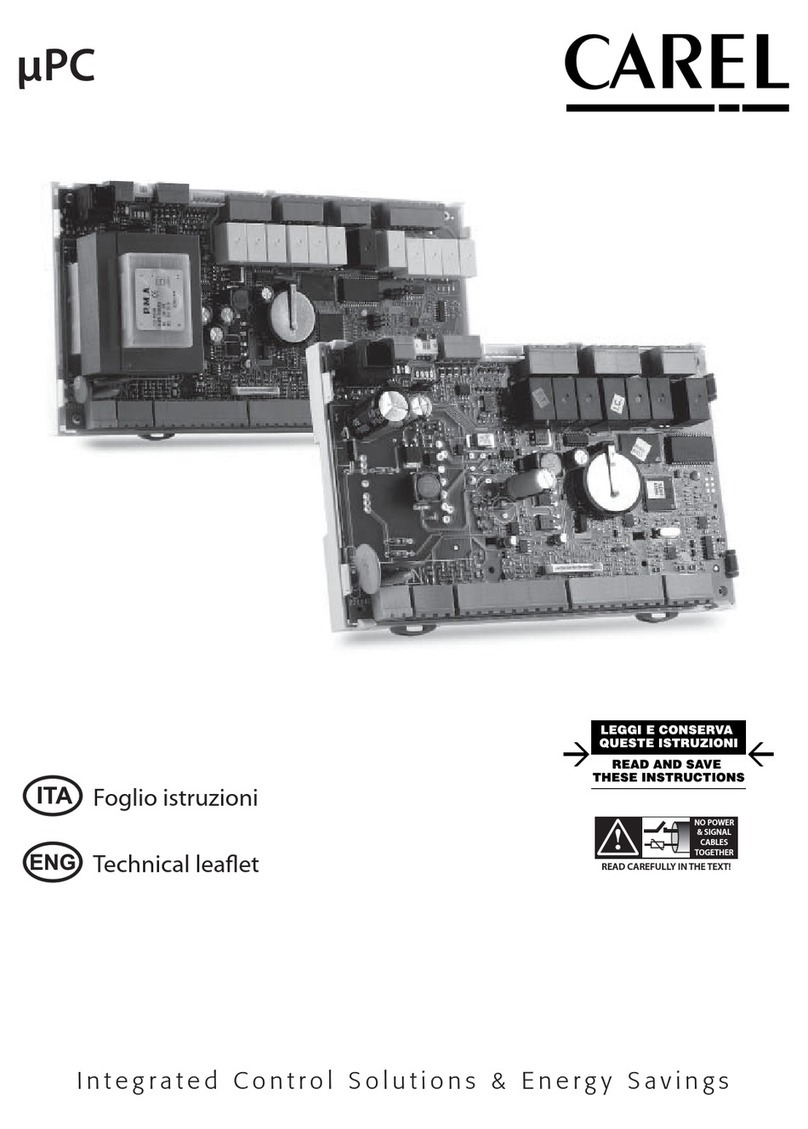
μPCII é un controllo elettronico programmabile sviluppato da Carel per applicazioni di condizionamento,
riscaldamento e refrigerazione e in generale del settore HVAC/R. Assicura una notevole flessibilità, consentendo
di realizzare soluzioni specifiche su richiesta del cliente. Attraverso l’utilizzo del software 1tool sviluppato da
Carel per i controlli programmabili assicura la massima flessibilità di programmazione adattabile per ogni
esigenza. µPCII controlla la logica ingressi/uscite, la comunicazione con il terminale della famiglia pgd, oltre
alla comunicazione con altri dispositivi grazie alla presenza di tre porte seriali. Gli ingressi/uscite universali
(denominati nello schema di connessione come U) possono essere configurati da programma applicativo
per collegare sonde attive e passive, ingressi digitali, uscite analogiche e PWM. Ciò aumenta la possibilità di
configurazione degli ingressi/uscite, Aumentando la flessibilità di utilizzo dello stesso controllo per diverse
applicazioni. La possibilità di utilizzo del software 1Tool, installabile su PC, per la creazione e la personalizzazione
del programma applicativo, la simulazione, la supervisione e la definizione della rete locale pLAN, permette
di sviluppare nuove applicazioni in breve tempo. Il caricamento del software applicativo sul controllo avviene
tramite il programma pCO Manager, disponibile gratuitamente sul sito http://ksa.carel.com.
Caratteristiche degli I/O
Ingressi Digitali Tipo: ingressi digitali a contatto pulito
Numero di ingressi digitali (DI): 4
Uscite analogiche Tipo: 0...10 Vdc continui, PWM 0...10 V 100 Hz sincroni con l’alimentazione,
PWM 0...10 V frequenza 100 Hz, PWM 0...10 V frequenza 2 KHz, corrente massima 10mA
Numero di uscite analogiche (Y): 3
Precisione delle uscite analogiche: +/- 3% del fondo scala
Canali Universali Bit conversione analogico digitale: 14
Tipo di ingresso selezionabile da applicativo: NTC, PT1000, PT500, PT100, 4...20mA, 0...1 V, 0...5
V, 0...10 V, Ingresso digitale contatto pulito, ingresso digitale veloce **
Tipo di uscita selezionabile da applicativo:
PWM 0/3,3 V 100 Hz, PWM 0/3,3 V 2 KHz, uscita analogica 0...10 V Massima corrente 2 mA
Numero di canali universali (U): 10
Precisione della lettura sonde passive: ± 0,5 C in tutto il range di temperatura
Precisione lettura sonde attive: ± 0,3% in tutto il range di tensione
Precisione uscite analogiche: ± 2% del fondo scala
Uscite digitali Gruppo 1 (R1), Potenza commutabile: NO EN 60730-1 1(1) A 250Vac (100.000 cicli)
UL 60730-1: 1 A resistivo 250Vac, 100.000 cicli
Gruppo 2 (R2), Potenza commutabile: NO EN 60730-1 1(1) A 250Vac (100.000 cicli)
UL 60730-1: 1 A resistivo 250Vac 100.000 cicli, 1/8Hp (1,9 FLA, 11,4 LRA) 250Vac, C300 pilot
duty 250Vac, 30.000 cicli
Gruppo 2 (R3, R4, R5), Potenza commutabile: NO EN 60730-1 2(2) A 250Vac (100.000 cicli)
UL 60730-1: 2 A resistivo 250Vac, C300 pilot duty 240Vac, 30.000 cicli
Gruppo 3 (R6, R7, R8), Potenza commutabile: NO EN 60730-1 6(4) A 250Vac (100.000 cicli)
UL 60730-1: 10 A resistive, 10 FLA, 60 LRA, 250Vac, 30.000 cicli
Tensione massima commutabile: 250Vac.
Potenza commutabile R2, R3 (SSR case mounting): 15 VA 110/230 Vac o 15 VA 24 Vac secondo il
modello acquistato
I relè all’interno dei gruppi 2 e 3 hanno isolamento principale tra di loro e deve essere applica-
ta la stessa tensione di alimentazione.
Attenzione nel gruppo 2, con presenza di SSR a 24Vac, l’alimentare deve essere SELV 24Vac.
Tra i diversi gruppi di relè può essere applicata una diversa tensione di alimentazione
(isolamento rinforzato).
Uscita Valvole
Unipolari
Numero di valvole: 2
Massima potenza per ogni valvola: 7 W
Tipo di piloltaggio: unipolare
Connettore valvola: 6 pin sequenza fissa
Alimentazione: 12 Vdc ±5%
Corrente massima: 0.3 A per ogni avvolgimento
Minima resistenza avvolgimento: 40 Ω
Lunghezza massima cavo: 2 m senza cavo schermato. 6 m con utilizzo di cavo schermato
connesso a terra da entrambi i lati (E2VCABS3U0, E2VCABS6U0)
** max. 6 sonde 0...5Vraz. e max. 4 sonde 4...20mA
Tab. 1
µPCII- Controllo programmabile integrato con e senza cover -
µPCII- Programable built-in controller with and without cover
+050001592 - rel. 1.2 date 10.12.2018
Descrizione connettori / Connector’s description
5b
3 4
1
2
6
79
11
12 105a
13
14 816
J1
J9 J11 J12 J14
J16 J17 J18 J19 J20 J21 J22 J23 J24
J10
J13
J2 J3 J4 J5 J6
J8
J7
15
G
G0
Out2
C2
Out3
C2
Out4
C2
Out5
C2
C2
V-IN
NO6
C6
NO7
C7
NO8
C8
U8
U9
U10
+Vdc
+5VR
GND
RX-/TX-
RX+/TX+
GND
RX-/TX-
RX+/TX+
GND
Vout
RX-/TX-
RX+/TX+
GND
N01
NC1
C1
U4
U5
+Vdc
+5VR
GND
U6
U7
+Vdc
+5VR
GND
DI1
DI2
DI3
DI4
GND
U1
U2
U3
GND
GND
Y1
Y2
Y3
RS485 enabled
pLAN 180 Ω disabled (*)
(*)180ohm
selection for end
of line resistor
pLAN connector
(J14,J15)
tLAN enabled
pLAN 180 Ω enabled
For Fb1
Connector
(J9, J10)
- for UP2A*: 230 Vac 50/60 Hz, +10%/-15%;
- for UP2B*: 24 Vac +10%/-15% 50/60 Hz,
28 to 36 Vdc +10%/-15%;
J15
Fig. 1
General characteristics
μPCII is a microprocessor-based electronic controller developed by CAREL for many applications in the
air-conditioning, heating and refrigeration sectors and solution for HVAC/R sector. It ensures absolute
versatility, allowing specific solutions to be created on customer request. Using 1tool software developed
by Carel for programmable controller it is assured maximum programming flexibility suitable for each
application. µPCII controls inputs outputs logic, the pGD user interface and others devices communication
thanks to three serial ports built in. The universal channel (called on the drawing U) could be configured
by application software to connect active and passive probes, free voltage digital inputs, analog outputs
and PWM outputs. This technology increase the configurability of input output lines and flexibility of the
product for different applications.The 1TOOL software installable on PC, for the creation and customization
of application software, simulation, monitoring and definition of pLAN networks, allows us to develop
new applications quickly. The loading of the application software is controlled using the program pCO
Manager, free available on the site http://ksa.carel.com.
I/O characteristics
Digital inputs Type: voltage-free contact digital inputs
Number of digital inputs (DI): 4
Analogue outputs Type: 0T10 Vdc continous, PWM 0T10V 100 Hz synchronous with power supply,
PWM 0...10 V frequency 100 Hz, PWM 0...10 V frequency 2 KHz, maximum current 10mA
Number of analogue outputs (Y): 3
Precision of analog outputs: +/- 3% of full scale
Universal channels Bit analogue-digital conversion: 14
Type of input selectable by software: NTC, PT1000, PT500, PT100, 4-20mA, 0-1V, 0-5V, 0-10V,
Voltage-free contact digital input, fast digital input **
Type of output selectable by software:
PWM 0/3,3V 100Hz, PWM 0/3,3V 2KHz, Analogue output 0-10V - Maximum current 2mA
Number of universal channels (U): 10
Accuracy of passive probes: ± 0,5 C in all temperature range
Accuracy of active probes: ± 0,3% in all temperature range
Accurancy of analogue output: ± 2% full scale
Digital outputs Group 1 (R1), Switchable power: NO EN 60730-1 1(1) A 250Vac (100.000 cycles)
UL 60730-1: 1 A resistive 30Vdc/250Vac, 100.000 cycles
Group 2 (R2), Switchable power: NO EN 60730-1 1(1) A 250Vac (100.000 cycles)
UL 60730-1: 1 A resistive 30Vdc/250Vac 100.000 cycles, 1/8Hp (1,9 FLA, 11,4 LRA) 250Vac,
C300 pilot duty 250Vac, 30.000 cycles
Group 2 (R3, R4, R5), Switchable power: NO EN 60730-1 2(2) A 250Vac (100.000 cycles)
UL 60730-1: 2 A resistive 30Vdc/250Vac, C300 pilot duty 240Vac, 30.000 cycles
Group 3 (R6, R7, R8), Switchable power: NO EN 60730-1 6(4) A 250Vac (100.000 cycles)
UL 60730-1: 10 A resistive, 10 FLA, 60 LRA, 250Vac, 30.000 cycles
Max switchable voltage: 250Vac.
Switchable power R2, R3 (SSR case mounting): 15VA 110/230 Vac or 15VA 24 Vac depends on the
model
The relays in groups 2 e 3 have basic insulation and the same power supply must be applied.
Attention for group 2, with 24Vac SSR, power supply must be SELV 24Vac.
Between different relays gruops could be applied different power supplies
(reinforced insulation).
Unipolar Valve
outputs
Number of valve: 2
Maximum power for each valve: 7 W
Type of duty: unipolar
Valve connector : 6 pin fixed sequence
Power supply: 12 Vdc ±5%
Max current: 0.3 A for each winding
Minimum winding resistance: 40 Ω
Maximum cable lenght: 2m without shielded cable. 6 m with shielded cable connected to
ground both on valve side and electronic controller side (E2VCABS3U0, E2VCABS6U0)
** max. 6 sonde 0...5Vraz. e max. 4 sonde 4...20mA
Tab. 1
Legenda:
1Alimentaz. 230 Vac per versione con trasformatore
(UP2A*********)
Alimentaz. 24 Vac per versione senza trasformatore
(UP2B*********)
2Canali universali
3Uscite analogiche
4Ingressi digitali
5a Uscita valvola 1
5b Uscita valvola 2
6Uscite digitali a relè tipo ad interruttore
7Ingresso tensione per uscite 2, 3, 4, 5
8Uscite digitali in tensione
9Uscita digitale di allarme
10 Connessione seriale pLAN
11 Connessione seriale BMS2
12 Connessione seriale Fieldbus
13 Connessione per terminale PLD
14 Dipswitch selezione
15 Scheda seriale opzionale
16 Led verde di alimentazione
Key:
1
Power supply 230Vac for version with trasformer
(UP2A*********)
Power supply 24Vac for version without trasformer
(UP2B*********)
2
Universal channel
3
Analog outputs
4
Digital inputs
5a
Valve output 1
5b
Valve output 2
6
Relay digital output switch type
7
Voltage inputs for digital output 2, 3, 4, 5
8
Voltage digital outputs
9
Alarm digital output
10
Serial line pLAN
11
Serial line BMS2
12
Serial line Fieldbus
13
PLD terminal connector
14
Dipswitch for selection
15
Optional serial card
16
Power supply - Green Led
Regole per lo smaltimento
• L’apparecchiatura (o il prodotto) deve essere oggetto di raccolta separata in conformità alle vigenti
normative locali in materia di smaltimento
• Non smaltire il prodotto come rifiuto solido urbano ma smaltirlo negli appositi centri di raccolta.
• Il prodotto contiene una batteria ed è quindi necessario rimuoverla separandola dal resto del prodotto
seguendo le istruzioni riportate di seguito prima di procedere al suo smaltimento.
• Un uso improprio o uno smaltimento non corretto potrebbe avere effetti negativi sulla salute umana
e sull’ambiente.
• In caso di smaltimento abusivo dei rifiuti elettrici ed elettronici sono previste sanzioni stabilite dalle
vigenti normative locali in materia di smaltimento.
Guidelines for disposal
• The appliance (or the product) must be disposed of separately in accordance with the local waste
disposal legislation in force.
• Do not dispose of the product as municipal waste; it must be disposed of through specialist waste
disposal centres.
• The product contains a battery that must be removed and separated from the rest of the product ac-
cording to the instructions provided, before disposing of the product.
• Improper use or incorrect disposal of the product may negative effects on human health and on the
environment.
• In the event of illegal disposal of electrical and electronic waste, the penalties are specified by local
waste disposal legislation.
NO POWER
& SIGNAL
CABLES
TOGETHER
READ CAREFULLY IN THE TEXT!
WARNING: separate as much as possible the probe and digital input signal cables from the cables carrying inductive
loads and power cables to avoid possible electromagnetic disturbance. Never run power cables (including the electrical panel wiring)
and signal cables in the same conduits.
IMPORTANT WARNINGS
The CAREL product is a state-of-the-art product, whose operation is specified in the technical documentation supplied with the product
or can be downloaded, even prior to purchase, from the website www.carel.com. - The client (builder, developer or installer of the final
equipment) assumes every responsibility and risk relating to the phase of configuration the product in order to reach the expected
results in relation to the specific final installation and/or equipment. The lack of such phase of study, which is requested/indicated in
the user manual, can cause the final product to malfunction of which CAREL can not be held responsible. The final client must use the
product only in the manner described in the documentation related to the product itself. The liability of CAREL in relation to its own
product is regulated by CAREL’s general contract conditions edited on the website www.carel.com and/or by specific agreements with
clients.
+050001592 - rel. 1.2 date 10.12.2018
Dimensioni / Dimensions
107
9.08
54.15
111.5
219
5.08
5.08 5.08
19.86
5.08
213.92
Ø 4
227.5
112.5
55
40
24 Vac
senza trasformatore
without transformer
230 Vac
con trasformatore
with transformer
Caratteristiche elettriche e meccaniche del controllo
Alimentazione:
230 Vac, +10...-15% UP2A*********;
24 Vac +10%/-15% 50/60 Hz,
28 to 36 Vdc +10 to -15% UP2B*********;
Massima Potenza assorbita: 25 VA
Isolamento tra alimentazione e controllo
• mod. 230 Vac: rinforzato
• mod. 24 Vac: rinforzato garantito dal trasformatore di alimentazione di sicurezza
Massima tensione connettori J1 e da J16 a J24: 250 Vac;
Sezioni minime dei conduttori uscite digitali: 1,5 mm2
Sezioni minime dei conduttori di tutti gli altri connettori: 0,5 mm2
Nota: per i cablaggi delle uscite digitali se si utilizza il prodotto a 70°C ambiente si devono usare cavi approvati
a 105°C.
Alimentazioni fornite
Tipo: +Vdc, +5 Vr per alimentazione sonde esterne +12 Vdc per alimentazione terminali
tensione nominale (+Vdc): 26 Vdc ±15% per modelli alimentazione 230 Vac (UP2A*********),
21 Vdc ±5% per modelli alimentazione 24 Vac (UP2B*********)
Max corrente disponibile +Vdc: 150 mA, totali prelevata da tutti i connettori, protetta da cortocircuito
Tensione nominale (+5 Vr): 5 Vdc ±2%
Massima corrente disponibile (+5 Vr): 60 mA, totali prelevata da tutti i connettori, protetta da cortocircuito
Tensione nominale (Vout): 26 Vdc ±15% per modelli alimentazione 230 Vac (UP2A*********),
21 Vdc ±5% Massima corrente disponibile (Vout) (J9): 100 mA, adatta per alimentare
il terminale THTUNE CAREL, protetta da cortocircuito
Caratteristiche prodotto
Memoria programma (FLASH): 4 MB (2MB BIOS + 2MB programma applicativo)
Precisione orologio interno: 100 ppm
Caratteristiche Batteria rimovibile: batteria Lithium bottone, CR2430, 3 Vdc
Durata della batteria: Minimo 8 anni in condizioni normali di funzionamento
Regole per la sostituzione della batteria: non sostituire la batteria, contattare Carel per la sostituzione
Utilizzo della batteria: la batteria è utilizzata unicamente per il corretto funzionamento dell’orologio quando
il prodotto non è alimentato e per memorizzare i dati nella memoria di tipo T del programma applicativo. L’utilizzo
del prodotto a basse temperature di funzionamento, riduce la durata della batteria. Sostituire la batteria se l’ora non
è aggiornata alla riaccensione del prodotto
Connessioni terminali disponibili
Tipo: tutti i terminali PGD con connettore dedicato J15, PLD con connettore dedicato J10,
THTune con connettore dedicato J9
Max distanza per il terminale PGD: 2 m tramite connettore telefonico J15,
50 m tramite cavo schermato AWG24 con connessione a terra da
entrambi i lati
Numero massimo di terminali collegabili: un terminale della famiglia pGD su J15 o J14. Un terminale THTune su conne-
tore J9, o in alternativa un terminale pLD su connetore J10 selazionando il protocollo tLAN su dip swith a bordo scheda
Linee di comunicazione disponibili
Tipo: RS485, Master per FieldBus1, Slave per BMS 2, pLAN
N.ro e tipo di linee disponibili: 1 linea non opstoisolata su connettore J11(BMS2).
1 linea non opstoisolata su connettore J9 (FieldBus), se non utlizzata dal terminale pLD su connettore J10.
1 linea non opstoisolata su connettore J14 (pLAN), se non utlizzata dal terminale pGD su connettore J15.
1 linea opzionale (J13), selezionabile tra le opz. disponbili da Carel
Massima lunghezza del cavo di connessione: 2m tramite cavo non schermato, 500 m tramite cavo schermato
AWG24 con connessione a terra da entrambi i lati
Lunghezza massima connessioni
Ingressi digitali universali e tutto quanto non diversamente specificato: inferiore a 10m
Uscite digitali: inferiore a 30 m
Linee seriali: si vedano indicazioni nelle relative sezioni
Condizioni di funzionamento
Stoccaggio: -40T70 °C, 90% rH non-cond.
Funzionamento: -40T70 °C, 90% rH non-cond.
Caratteristiche meccaniche
Dimensioni: 13 DIN rail modules, 228 x 113 x 55 mm
Ball pressure test: 125 °C
Altre caratteristiche
Inquinamento ambientale: livello 2
Grado di protezione: IP00
Classe di la protezione contro le scosse elettriche: da integrare su apparecchiature di Classe I e/o II
Insolamento materiale: PTI175. Tensine nominale di impulso: 2.500V.
Periodo delle sollecitazioni elettriche delle parti isolanti: lungo
Tipo azioni: 1.C (Relè); 1.Y (110/230V SSR); SSR 24Vac non è garantita la disconnessione elettronica.
Tipo disconnessione o microinterruzione: microinterruzione
Categoria di resistenza al calore e al fuoco: categoria D (UL94 - V2)
Immunità contro le sovratensioni: categoria II
Classe e struttura del software: Classe A
Non toccare o manomettere il dispositivo quando alimentato
Tab. 2
Fig. 2
CAREL si riserva la possibilità di apportare modifiche o cambiamenti ai propri prodotti senza alcun preavviso.
Mechanical and Electrical specications
Power supply:
230 Vac, +10...-15% UP2A*********;
24 Vac +10%/-15% 50/60 Hz,
28 to 36 Vdc +10 to -15% UP2B*********;
Max power input : 25 VA
Insulation between power supply and instrument
• mod. 230Vac: reinforced
• mod. 24Vac: reinforced ensured by power supply of safety transformer
Max voltage connectors J1 and from J16 to J24: 250 Vac;
Minimum section of the wires - digital outputs: 1,5 mm2
Minimum section of wires of all others connectors: 0,5mm2
Note: for digital output cabling if the product is used at 70C ambient temperature 105C cable approved have
to be used.
Power supply
Type: +Vdc, +5Vr for power supply for external probe ,+12Vdc for terminal power supply
Rated power supply voltage (+Vdc): 26Vdc ±15% for models 230Vac power supply (UP2A*********),
21Vdc ±5% for models 24Vac power supply (UP2B*********)
Max current available +Vdc: 150mA, total taken from all connectors, protected against short-circuits
Rated power supply voltage (+5Vr): 5Vdc ±2%
Max current available (+5Vr): 60mA, total taken from all connectors, protected against short-circuits
Rated power supply voltage (Vout): 26Vdc ±15% for models 230Vac power supply (UP2A*********),
21Vdc ±5% Max current available (Vout) (J9): 100mA, suitable for power supply
THTUNE CAREL terminal, protected against short-circuits
Product specications
Program memory (FLASH): 4MB (2MB BIOS + 2MB application program)
Internal clock precision: 100 ppm
Battery type: Lithium button battery (removable), CR2430, 3 Vdc
Battery lifetime characteristics of removable battery: Minimum 8 years in normal operating conditions
Rules for battery substitute: Do not change battery, contact customer service of Carel for changing
Use of Battery: the battery is used only for the proper running of internal watch when not powered and to store
data on memory type T of application software. Replace the battery if the time is not updated when restarting the
product
User interface available
Type: all the pGD terminals with connector J15, PLD terminal with connector J10,
THTune with connector J9.
Max distance for PGD terminal: 2m by telephone connector J15,
50m by shield-cable AWG24 connected to ground both side and
electronic controller side
Max. number of user interface: One user interface of pGD familiy on the connector J15 or J14. One THTune user interface
on J9 connector, or alternatively PLD terminal with connector J10 choosing tLAN protocol on the on board dip switch
Communication lines available
Type: RS485, Master for FieldBus1, Slave for BMS 2, pLAN
N.ber of available linees: 1 line not optoinsulated on J11 connector (BMS2).
1 line not optoinsulated on J9 connector (FieldBus), if not used from pLD user interface on J10 connector.
1 line not optoinsulated on J12 connector (pLAN), if not used from pGD user interface on J15 connector.
3 lines no-optoisolated (J9, J11, J14), 1 optional (J13), selectable from Carel optionals
Maximum connection cable-lenght: 2m without shield-cable, 500m by shield-cable AWG24 connected to ground
both side and electronic controller side
Maximum connections lenght
Universal digital inputs and everything without different specification: less than 10m
Digital outputs: less than 30m
Serial Lines: check indication on relevant section
Operating conditions
Storage: -40T70 °C, 90% rH non-condensing
Operating: -40T70 °C, 90% rH non-condensing
Mechanical specications
Dimensions: 13 DIN rail modules, 228 x 113 x 55 mm
Ball pressure test: 125 °C
Other specications
Environmental pollution: 2 level
Index of protection: IP00
Class according to protection against electric shock: to be incorporated into Class I and/or II appliances
Insulation material: PTI175. Rated impulse voltage: 2.500V.
Period of stress across the insulating parts: long
Type of action: 1.C (Relays); 1.Y (110/230V SSR), SSR 24Vac electronic disconnection is not guaranteed
Type of disconnection or microswitching: microswitching
category of resistance to heat and fire: category D (UL94 - V2)
Immunity against voltage surges: category II
software class and structure: Class A
To not touch or maintenance the product when power supply is applied
Tab. 2
CAREL reserves the right to modify the features of its products without prior notice.
Model UP2***3***
106
112.5
227.5
141.5
78.4
Fig. 3
Istruzioni per il montaggio / Mounting instruction
A
B
SX
SX DX
DX
Fig. 4
Nota:
• Eseguire la cablatura dei connettori unicamente senza le parti plastiche A e B montate. Prima di fornire
alimentazione al prodotto montare le parti A e B fissando nella relativa sede prima il lato destro e poi il
lato sinistro con movimento rotatorio come mostrato in figura.
Il montaggio della parti A e B permette di raggiungere una maggiore sicurezza elettrica per l’utente.
Note:
•
To cable the connectors, the plastic parts A and B have not be mounted. Before to power on the product
please to mount the A and B parts staring into the relative seat before the right side and then the left side
with rotary movement as shown in the figure.
The assembly of plastic parts A and B let to reach a greater electrical safety for the user.
CAREL Industries HQs
Via dell’Industria, 11 - 35020 Brugine - Padova (Italy)
Tel. (+39) 0499716611 – Fax (+39) 0499716600 – e-mail: [email protected] – www.carel.com

Other Carel Controllers manuals

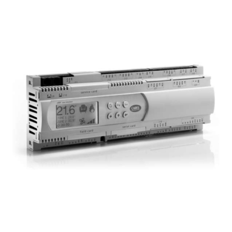
Carel pCO User manual

Carel

Carel pCO User manual

Carel uC2SE User manual

Carel

Carel uC2SE User manual

Carel ADCD000110 User manual

Carel

Carel ADCD000110 User manual

Carel ADE 10 Series User manual

Carel

Carel ADE 10 Series User manual

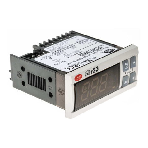
Carel ir33 smart User manual

Carel

Carel ir33 smart User manual

Carel EVD evolution User manual

Carel

Carel EVD evolution User manual

Carel mboss Manual

Carel

Carel mboss Manual

Carel PJEZS Series User manual

Carel

Carel PJEZS Series User manual

Carel ir33 smart User manual

Carel

Carel ir33 smart User manual

Carel DN33 Universale Series User manual

Carel

Carel DN33 Universale Series User manual

Carel uChiller UCHBP00000190 User manual

Carel

Carel uChiller UCHBP00000190 User manual

Carel pCO5+ User manual

Carel

Carel pCO5+ User manual

Carel UltraCella Instruction Manual

Carel

Carel UltraCella Instruction Manual

Carel pCO Series Troubleshooting guide

Carel

Carel pCO Series Troubleshooting guide

Carel mboss Manual

Carel

Carel mboss Manual

Carel WB000S series User manual

Carel

Carel WB000S series User manual

Carel pCO3 series User manual

Carel

Carel pCO3 series User manual

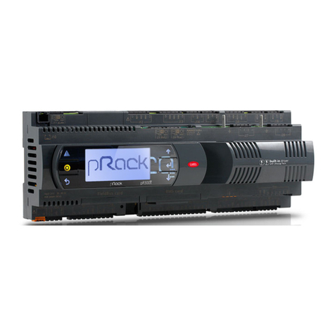
Carel pRack pR300T User manual

Carel

Carel pRack pR300T User manual

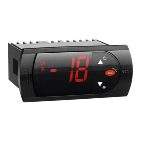
Carel easy User manual

Carel

Carel easy User manual

Carel pCO1 series User manual

Carel

Carel pCO1 series User manual

Carel FSC Series User manual

Carel

Carel FSC Series User manual

Carel ir33+ User manual

Carel

Carel ir33+ User manual

Carel compactSteam CHF User manual

Carel

Carel compactSteam CHF User manual

Carel boss User manual

Carel

Carel boss User manual

Popular Controllers manuals by other brands

Martin Audio CMX3A - SCHEMATICS manual

Martin Audio

Martin Audio CMX3A - SCHEMATICS manual

dji RM500 quick start guide

dji

dji RM500 quick start guide

salmson COFFRETS EC-DRAIN Installation and starting instructions

salmson

salmson COFFRETS EC-DRAIN Installation and starting instructions

PowerBox Systems voltage regulator instruction manual

PowerBox Systems

PowerBox Systems voltage regulator instruction manual

AUTLED LC-012-004 user manual

AUTLED

AUTLED LC-012-004 user manual

DayTronic 4000 Series instruction manual

DayTronic

DayTronic 4000 Series instruction manual

CompAir DELCOS XL Series Translation of the original operating instructions

CompAir

CompAir DELCOS XL Series Translation of the original operating instructions

Elan S6 Specifications

Elan

Elan S6 Specifications

Digitrax DN143IP user manual

Digitrax

Digitrax DN143IP user manual

Elation PIXEL DRIVER 1000IP user manual

Elation

Elation PIXEL DRIVER 1000IP user manual

National Instruments cRIO-9063 Getting started guide

National Instruments

National Instruments cRIO-9063 Getting started guide

JUMO diraTRON Series Interface description

JUMO

JUMO diraTRON Series Interface description

LG LCC-K1000 owner's manual

LG

LG LCC-K1000 owner's manual

4qd Pro-120 Series instruction manual

4qd

4qd Pro-120 Series instruction manual

Sunricher SR-1007 Series manual

Sunricher

Sunricher SR-1007 Series manual

Siemens AP 118 Technical product information

Siemens

Siemens AP 118 Technical product information

Lennox RG10F2-MMA manual

Lennox

Lennox RG10F2-MMA manual

Mitsubishi Electric Melservo JE Series instruction manual

Mitsubishi Electric

Mitsubishi Electric Melservo JE Series instruction manual

manuals.online logo
manuals.online logoBrands
  • About & Mission
  • Contact us
  • Privacy Policy
  • Terms and Conditions

Copyright 2025 Manuals.Online. All Rights Reserved.