Cembre RHU600 User manual

1
RHU600
17 M 232 E
17
M
2
32
E
ENGLISH
HYDRAULIC PRESSHEAD
OPERATION AND MAINTENANCE
MANUAL

2
2
3
4
1
1234
WARNING
Before using the tool, carefully read the instructions in this manual.
When operating the tool, keep hands away from the danger zone.
Operate only with dies and product inserted.
Use this tool for its intended purpose only.
Inspect tool before use, replace any worn or damaged parts.
Inspect pump hydraulic hoses and couplings before each use.
Clear work area.
Always maintain a firm grip on the tool during operation.
DANGER
The user should be properly
trained in the correct
procedures required for work
on or around electrical lines.
ELECTROCUTION
HAZARD
Operating and safety procedures
may vary in accordance with
the guidelines of each utility.
For your own safety, ensure
that you fully comply with all
“safe operation” practices required
by your respective power utility.
BEFORE USING THIS TOOL, READ THE SAFETY
WARNINGS
and recommended practices described in
the manual. Failure by the operator to read and fully
understandthewarningswillleavethispersonunquali-
fied to use and operate the tool. Failure to observe all
warnings and instructions may result in property
damage, severe personal or third party injury or death.
WARNING
CAUTION
TG. 0934
CAUTION
TG. 0947
Before operating make sure the
latch is secure. Latch improperly
secured may cause tool damage
and personal injury.
TG0356

3
22
22 9
13
21
27
201
RHU600-WS
HS600
FIG. 1
202
100
4

4
HYDRAULIC PRESSHEAD
RHU600
1. GENERAL CHARACTERISTICS
– Application range: suitable for installing compression connectors on conductors up
to ...........................................................................1022 mm2 (2156 MCM) Al and Cu
– Crimping force:.......................................................................................600 kN (67 sh ton)
– Max. operating pressure:....................................................................700 bar (10,000 psi)
– Oil necessary (displacement):............................................................320 cm3(18.9 cu. in)
– Ram stroke: ...............................................................................................34 mm (1.33 in.)
– Weight RHU600 (head with support):.............................................22,4 kg (49.3 lbs)
– Weight RHU600-WS (head without support):..............................19 kg (41.8 lbs)
– Weight SH600 (support):.....................................................................3,4 kg (7.5 lbs)
– Dimensions mm (inch):
– Description: (Ref. to Fig. 1)
4 - HEAD RELEASE KNOB
9 - DIE HOLDER LATCH
13 - U-FORK
21 - MALE QUICK COUPLER
22 - HANDLE
27 - HANGER (for suspended use)
100 - HEAD SUPPORT (for use on a stable, level surface)
201 - TOP DIE HOLDER
202 - RAM
210 (8.26)
346 (13.6)
434 (17.1)
199 (7.83)
204 (8.03)
245 (9.64)
ø 137 (5.39)

5
2. INSTRUCTIONS FOR USE
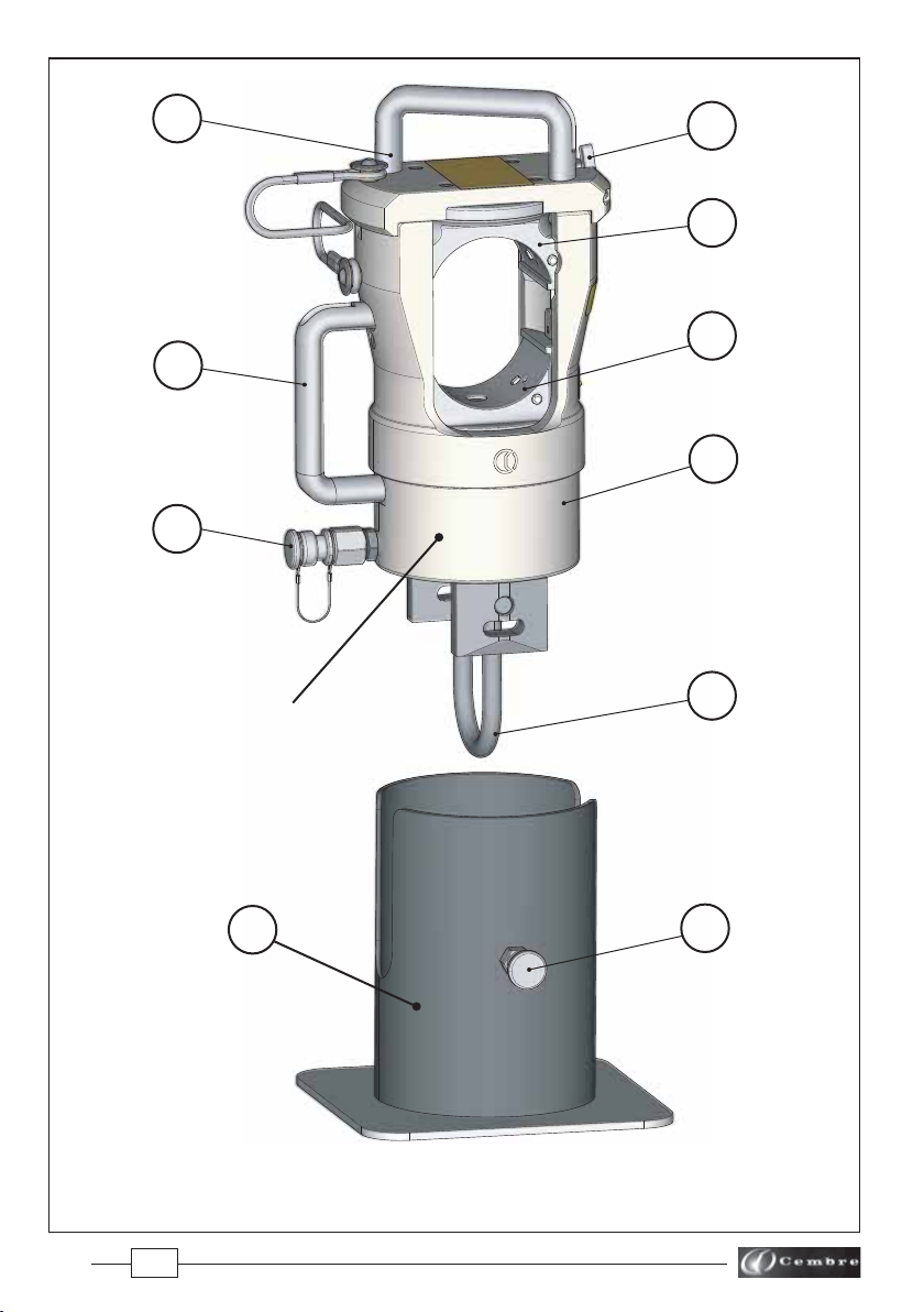
For use on a level and stable surface, e.g the ground, the head should be mounted and locked wih
the knob (4) on the HS600 support base provided.
Alternatively, the head may be suspended for use, via the integral hanger (27), ensuring the sus-
pension method is secure and safe.
2.1) Setting
– Connect the presshead to the pump hose; the head is equipped with a "self-lock" quick male
coupler and can be connected to a Cembre hydraulic pump developing 700 bar (10,000 psi)
pressure.
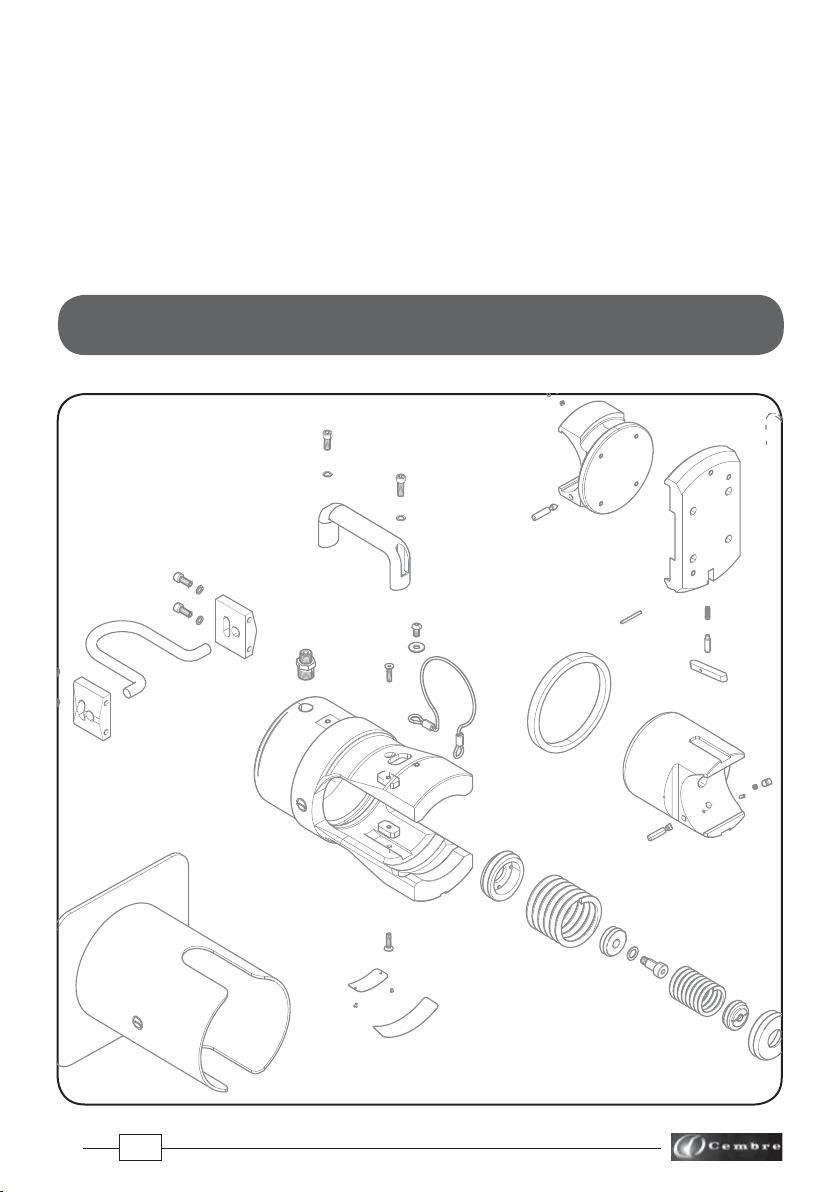
2.2) Die insertion (Ref. to Fig. 3)
Make sure that the top die holder and the latch are correctly located.
BEFORE OPERATING MAKE SURE THE LATCH IS SECURE. LATCH IMPROPERLY SECURED CAN CAUSE
TOOL DAMAGE AND PERSONAL INJURY.
– Select the appropriate die set for the connector.
– Insert the die (90) in the upper seat of the top die holder (201) until it is locked by die/head pin (6).
To ease the die insertion, keep die/head release pin (4) depressed.
– Insert the die (91) into the seat on the ram (202) until it is locked by die/ram retaining pin (6);
To ease this operation, keep die/ram release pin (4) depressed.
NEVER PRESSURIZE THE HEAD WITHOUT THE DIE IN PLACE AS SERIOUS DAMAGE AND/OR PERSONAL
INJURY MAY RESULT.
2.3) Die positioning
– Insert the conductor into the connector (see § 2.6).
– Locate the connector between the dies at the desired crimp position.
– Operate the pump until the dies touch the connector.
Make sure that dies are exactly positioned on desired crimp point, otherwise re-open dies
following instructions as per § 2.5 and position the connector again.
2.4) Crimping
– Operate the pump to advance the ram until the die faces touch.
It is recommended to continue pumping until the maximum pressure valve is activated and a
“click” is heard.
– Re-open dies (see § 2.5) and repeat steps above as necessary.
2.5) Die opening
– Fully discharge the oil pressure from the pump to retract the ram (202) and release the crimped
connector.
CHECK THAT THE RAM IS COMPLETELY RETRACTED BEFORE DISCONNECTING THE HOSE FROM THE
HEAD.

6
2.6) Head opening (Ref. to Fig. 4)
When required, the upper part of the head can be disconnected to permit an easy introduction of
the connector or, if necessary, the connector removal after crimping; operate as follows:
– Hold the handle (22), press the latch (9) and turn the top of the head through 90 degrees.
– Introduce the connector then replace the top of the head.
Before proceeding with the crimping operations, please verify that the head is correctly reassem-
bled and latch (9) is correctly located.
3. MAINTENANCE
The head is robust and requires very little daily maintenance.
Inspect for wear and damage. Worn or damaged parts may malfunction during head operation.
The parts must be replaced if signs of wear or damage are evident.
Compliancewiththefollowingpointsshouldhelp tomaintaintheoptimum performanceof the tool.
3.1) Accurate cleaning
Dust, sand and dirt are a danger for any hydraulic device.
Avoid putting the head on muddy or dusty ground as dirt particles may score the ram and create
oil leaks.
Every day, after use, the head must be wiped with a clean cloth, taking care to remove any residue,
especially around moving parts.
3.2) Replacement of the automatic coupler
To replace the automatic coupler proceed as follows:
– Remove the old coupler.
– Carefully clean the thread to remove the old sealant.
– Apply Teflon tape to the thread.
– Fit the new automatic coupler and tighten to 30 Nm (22 lbf ft).
3.3) Storage (Ref. to Fig. 2)
When not in use, the head should be stored and transported in the specific steel case to prevent
damage.
Steel case: VAL600, size 480x235x260 mm (18.9x9.2x10.2 in.) weight 8,6 kg (18.9 lbs) suitable for
storing the head complete with support.
FIG. 2
VAL600 METAL CASE

7
SPARE PARTS LIST
RHU600
4. RETURN TO Cembre FOR OVERHAUL
In the case of a breakdown, contact our Area Agent who will advise you on the problem and give
you the necessary instructions on how to dispatch the tool to our nearest service Centre; if possible,
include a copy of the Test Certificate supplied by Cembre with the tool or, if no other references
are available, indicate the approximate purchase date and the tool serial number.

8
203
29
28
14
22
33
21
3
2
1
27
3
2
1
100
13
37
36 14
35
15
19
23
1
4
32
41
TABLE 1
Tool serial number

9
23
31
16
30
6
5
40
4
7
5
6
24 11
9
10
20
18
4
1
26
25
202
201
8
23
1
22
39

10
The items marked "K" are those Cembre recommend replacing if the tool is disassembled.
When ordering spare parts always specify the following:
- code number of item - name of item - type of tool - serial number of tool
TABLE 1
Code N° DESCRIPTION
6640112 1 D.6 SCHNORR WASHER 8
6900325 2 M6x16 SCREW 4
6780166 3 HANGER BLOCK 2
6780119 8 DIE HOLDER SUPPORT 1
6640185 9 LATCH 1
6600019 10 PIN 1
6520529 11 SPRING 1
6280167 13 FORK 1
6900281 14 SCREW M5x20 2
6100044 15 KEY 2
6640194 16 NORD-LOCK WASHER 1
6362090 18 SEAL 1K
6525072 19 NIPPLE 1
6520441 20 COMPLETE SPRING 1
6060120 21 Q14-MS QUICK COUPLER 1
6490074 22 HANDLE 2
6900299 23 M6x20 SCREW 3
6760166 24 D.3X30 PIN 1
6640096 25 D.5 SCHNORR WASHER 4
6900253 26 M5x14 SCREW 4
6580642 27 HANGER 1
6362089 30 SEAL 1K
6900559 31 SCREW 1
6900325 33 M6x16 SCREW 1
6800186 34 PROTECTION CAP
6650118 35 ø2,5x3,5 RIVET 2
6232567 36 TG.0778 TOOL NAMEPLATE 1
6232006 37 TG.0356 WARNING LABEL 1
6232692 39 TG.0935 WARNING LABEL 1
6232691 41 TG.0945 WARNING LABEL 1
2640260 100 COMPLETE HEAD SUPPORT (HS600) 1
6620350 100 4 RELEASE KNOB 1
6506657 201 COMPLETE DIE HOLDER 1
6620443 201 4 PIN 1
6522006 201 5 SPRING 1
6620339 201 6 PIN 1
6760040 201 7 D.3x8 SPLIT PIN 1
6620541 202 COMPLETE RAM 1
6620443 202 4 PIN 1
6522006 202 5 SPRING 1
6620339 202 6 PIN 1
6760415 202 40 POSITIONING PIN 1
6170082 203 COMPLETE CABLE 1
6900291 203 28 M6x16 SCREW 2
6640114 203 29 Ø6,5xØ24x2 WASHER 2
6080098 203 32 BUSH 2
QtyItem
The guarantee is void if parts used are not Cembreoriginal spares.

11
4
202
201
91
90
1
2
3
9
22
FIG. 4
FIG. 3
6
CAUTION
BEFORE OPERATING MAKE SURE THE
LATCH (9) IS SECURE.
LATCH IMPROPERLY SECURED CAN
CAUSE TOOL DAMAGE AND PERSONAL
INJURY.

12
This manual is the property of Cembre: any reproduction is forbidden without written permission.
Cembre Ltd.
Dunton Park
Kingsbury Road, Curdworth - Sutton Coldfield
West Midlands B76 9EB (UK)
Tel.: 01675 470440 - Fax: 01675 470220
E-mail: [email protected]
www.cembre.co.uk
Cembre S.p.A.
Via Serenissima, 9
25135 Brescia (Italia)
Telefono: 030 36921
Telefax: 030 3365766
E-mail: [email protected]
www.cembre.com
Cembre S.a.r.l.
22 Avenue Ferdinand de Lesseps
91420 Morangis (France)
Tél.: 01 60 49 11 90 - Fax: 01 60 49 29 10
CS 92014 - 91423 Morangis Cédex
E-mail: [email protected]
www.cembre.fr
Cembre España S.L.U.
Calle Verano 6 y 8
28850 Torrejón de Ardoz
Madrid (España)
Teléfono: 91 4852580 - Fax: 91 4852581
E-mail: [email protected]
www.cembre.es
Cembre GmbH
Heidemannstraße 166
80939 München (Deutschland)
Telefon: 089 3580676
Telefax: 089 35806777
E-mail: [email protected]
www.cembre.de
Cembre Inc.
Raritan Center Business Park
181 Fieldcrest Avenue
Edison, New Jersey 08837 (USA)
Tel.: (732) 225-7415 - Fax: (732) 225-7414
E-mail: [email protected]
www.cembreinc.com
www.cembre.com
IKUMA GmbH & Co. KG
Boschstraße 7
71384 Weinstadt (Deutschland)
Telefon: 07151 20536-60
Telefax: 07151 20536-80
E-mail: [email protected]
www.ikuma.de
cod. 6261083
Table of contents
Other Cembre Power Tools manuals

Cembre
Cembre B600CND User manual

Cembre
Cembre PNB-4KE User manual

Cembre
Cembre MTE1-S User manual

Cembre
Cembre B1350L-C User manual

Cembre
Cembre B54D-D6 User manual

Cembre
Cembre PNB-3 Series User manual

Cembre
Cembre B1300-C-KV User manual

Cembre
Cembre RHU 1000 Owner's manual

Cembre
Cembre B54M-D6A User manual

Cembre
Cembre B500 User manual

Cembre
Cembre B135-C-KV User manual

Cembre
Cembre B540NDK-BV User manual

Cembre
Cembre B1300-C User manual

Cembre
Cembre B600 User manual

Cembre
Cembre BTEPE2.DET10 User manual

Cembre
Cembre RHU81-D User manual

Cembre
Cembre B35-TC025 User manual

Cembre
Cembre PNB-7KE User manual

Cembre
Cembre B54MD-D6 User manual

Cembre
Cembre HT131LN-C User manual