CIAT OPERA User manual

1
OPERA
HEAT PUMPS - AIR CONDITIONING - REFRIGERATION - AIR HANDLING - HEAT EXCHANGE - NA 15.689 A
Drycoolers
Air-cooled condensers
The OPERA range, available in drycooler or air-cooled condenser versions, is particularly suited to service sector, industrial
and healthcare applications.
Drycoolers in the OPERA range are mainly designed for
cooling water or glycol/water mix for:
nCondensers for water chillers,
nGenerators,
nFree cooling,
nProcesses and machines (presses, compressors, etc.).
Air-cooled condensers in the OPERA range are mainly
designed for the condensation of refrigerants for water
chillers, as a "split system".
These devices are designed to be installed outdoors.
OPERA is a large modular range, which offers:
n3 casing lengths (S, M or L module), allowing either the
dimensions, the capacity or the power consumption to be
optimised.
nA range of sizes, from 1 to 14 fans.
n2 impeller diameters, 800 or 910 mm.
nSeveral rotation speeds, from 330 to 1 000 rpm.
nSeveral configurations: horizontal or vertical unit with forced or
induced draught for high temperatures.
Various combinations of these elements, as well as the choice
of a number of options, allow us to provide devices that are
adapted to a lange range of applications and environments.
Use
Range
Capacity: up to 1100 kW
MORE
n
More efficient
n
More flexible
n
More intelligent
for LESS
n
Less energy
n
Less time
n
Less noise
134a
407C
410A 404A
Water
misting
Free cooling

2
heat pumps - aIR CONDItIONING - ReFRIGeRatION - aIR haNDLING - heat eXChaNGe - Na 15.689 a
Drycoolers
Air-cooled condensers
OPERA
Coil
Copper tubing and manifolds, high-performance aluminium fins, resistant to fouling.
Anti-shear system for tube bundles.
Pipings for drycooler: ISO PN16 type 02A rotating flanges in line with NFEN1092 in 304L stainless steel (1 or 2 input(s)/
outputs(s) depending on the flow rate) – The tubes are sealed with plastic caps to protect the bundle.
Tubes for condenser: copper (1 input/output per refrigerating circuit for units with 1 fan line, 2 inputs/outputs for units with 2 fan
lines). Delivered pressurised with nitrogen.
Fan motor assemblies
Profiles collars with galvanised steel with polyester powder coating on the internal and external surfaces.
Aluminium and polypropylene impellers.
Class F motor - IP54 - 3PH400V +/-10% 50Hz+/-2% - Standard connection to the motor terminal boxes
Black protective grille compliant with standard BS ISO 12499.
Individual partitioning.
The motors are also available in a 60 Hz version or in other voltages.
Casing
Galvanised steel with polyester powder coating on the internal and external surfaces. Assembly using stainless rivets and
LANTHANUM nuts and bolts for the feet.
Feet
Galvanised steel with polyester powder coating on the internal and external surfaces.
Protective enclosures on the elbows and manifolds
Excellent resistance to corrosion
The casing boasts category C3 protection against corrosion,
in line with ISO standard 12944-2 – colour RAL 7035 (light grey)
DescRiption
1
1
2
2
4
4
3
3
5
5
5
Each device is tested:
nThe coil sealing is subjected to an underwater airtightness
test.
nFor devices with the terminal box or electrical cabinet option:
rotation tests, dielectric tests, current measurement.
The OPERA range complies with the following European
directives:
nMachinery Directive 2006/42/EC,
nEMC Directive 2004/108/EC,
nPressure Equipment Directive (PED) 97/23 EC.
Designation (example)
OPERA DLN 9124-2 SHI 690A
Rotation speed
Draught (I = Induced, F = Forced)
Position (H = Horizontal, V = Vertical)
Coil type (S = Single, D = Double, T = Twin, Z = Drainable)
Number of fan lines (1 or 2)
Number of coil rows
Number of fans
Impeller diameter (8 = 800, 9 = 900 mm)
Module size (S = Short, M = Medium, L = Long)
D = Drycooler C = Condenser

3
OPERA
HEAT PUMPS - AIR CONDITIONING - REFRIGERATION - AIR HANDLING - HEAT EXCHANGE - NA 15.689 A
Drycoolers
Air-cooled condensers
options foR each application
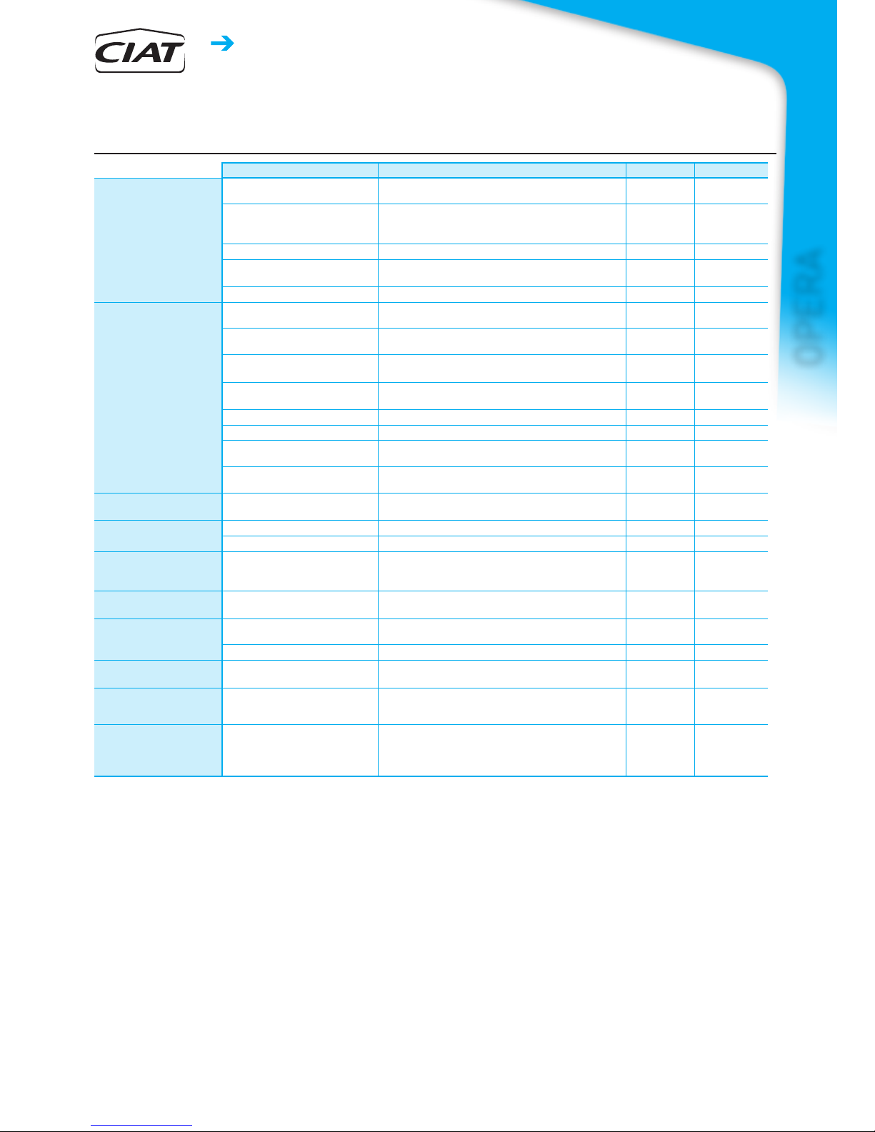
Options Description/Advantages DRYCOOLER CONDENSER
Protection adapted
for the environment
Pre-coated aluminium ns
Improves the resistance of the blades to corrosion.
For low corrosion environments. ● ●
High efciency coating on the
nned bundle:
ALUCOAT®507 or HERESITE
Improves the resistance of the blades to corrosion.
For corrosive environments. ● ●
Stainless steel tube bundle
For corrosive uids. ●
Corrosiveness resistance
category C5M
Casing and fan motor assemblies for corrosive environments. ● ●
ATEX II 2G/3G
For explosive atmospheres. ● ●
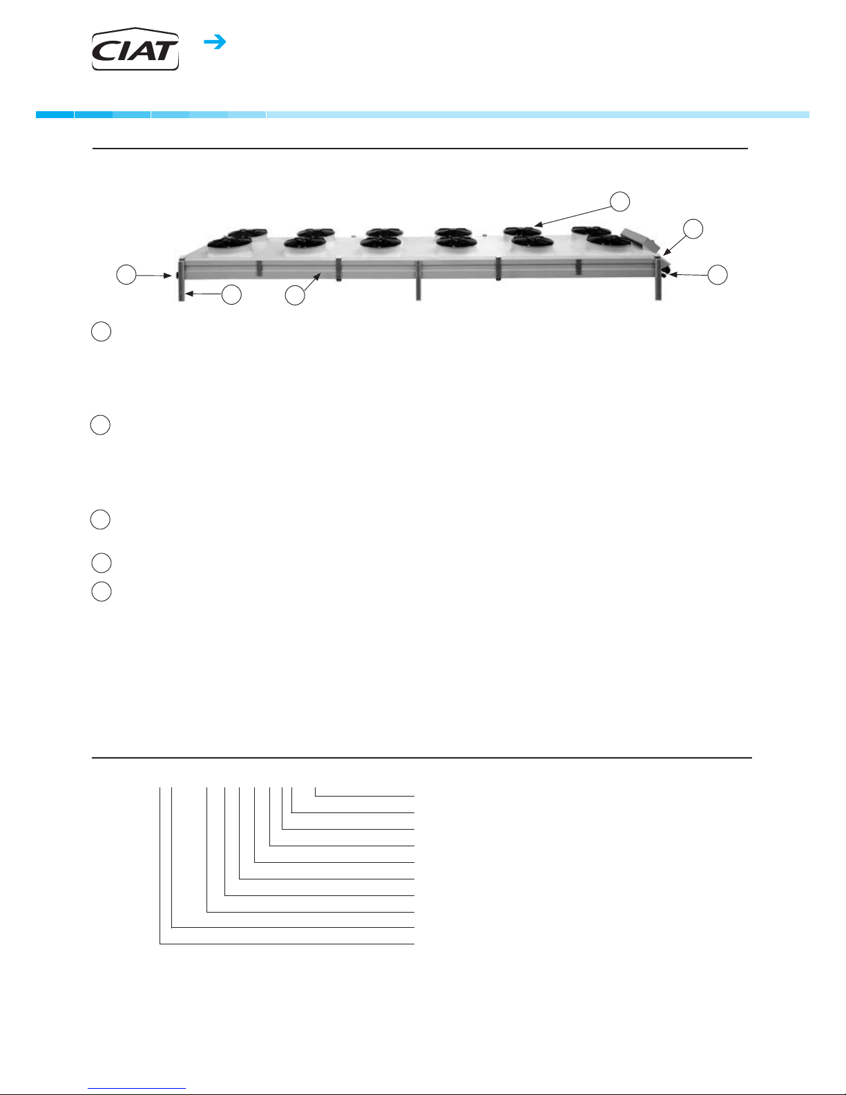
Quick, simple installation
Terminal box
Connection to the terminals of each motor on the front panel
of unit. ● ●
Protection cabinet
Protected by a thermal-magnetic circuit breaker on each
motor. ●
Control cabinet with
AeroCONNECT
Protection for motors and stage regulation provided by an
electronic board according to temperature or pressure. ● ●
Control cabinet with stages on
terminals
Motor protection and stages controlled by the customer
control. ●
Maintenance switch
For stopping individual motors. ● ●
Companion anges
In stainless steel, with gaskets and bolts. ●
Raised feet
To ensure a good ow of air depending on how the units are
installed: against a wall, side by side, etc. ● ●
Blade protective screen
Protection against hail, impacts, etc.
For forced draught, vertical units. ● ●
Installation surface
constraints Vertical position
For narrow terraces. ● ●
Optimised, secure
transport
Stacking of 2 identical devices
● ●
Skid for transport by container
Secure transport and easy loading/unloading. ● ●
Optimisation
of electrical consumption
and sound levels
EC motor
(with electronic switching)
Variable speed control from 0 to 100% using a 0/10V signal.
With the control cabinet via electronic board option, the
device is self-regulating
● ●
High-temperature
uid application Forced draught
Motors in the ow of fresh air. ●
Generator application Double circuit drycooler
Cooling of 2 water circuits (LT – HT) in series using air from
just 1 unit. ●
Expansion vessel
Max permissible pressure: 0.5 bar eff. ●
Application for water
without glycol Drainable coil
Device located on a slope to prevent frost - drainage by gravity ●
Free cooling application Free cooling valve kit
Valves with motor and sensor, controlled by the electronic
board. Controlled according to the operation of the drycooler
or chiller.
●
Application with
adiabatic cooling AEROFRESH (water misting
into the air ow)
Size of the unit reduced by cooling of the ambient air.
Operates completely safely due to the antibacterial
treatment applied to the water.
● ●

4
heat pumps - aIR CONDItIONING - ReFRIGeRatION - aIR haNDLING - heat eXChaNGe - Na 15.689 a
Drycoolers
Air-cooled condensers
OPERA
AC MOTORS EC MOTOR
Speed 900 700 690 560 425 300
510 740
Wiring ΔYΔYΔY
I (A) P(kW) I (A) P(kW) I (A) P(kW) I (A) P(kW) I (A) P(kW) I (A) P(kW) I (A) P(kW) I (A) P(kW)
8010-1
3.65 1.98 2.4 1.43 2.1 0.895 1.05 0.56 0.42 0.194 0.35 0.075 0.49 0.298 1.4 0.918
8020-1
7.3 3.96 4.8 2.86 4.2 1.79 2.1 1.12 0.84 0.388 0.7 0.15 0.98 0.596 2.8 1.836
8030-1
10.95 5.94 7.2 4.29 6.3 2.685 3.15 1.68 1.26 0.582 1.05 0.225 1.47 0.894 4.2 2.754
8040-1
14.6 7.92 9.6 5.72 8.4 3.58 4.2 2.24 1.68 0.776 1.4 0.3 1.96 1.192 5.6 3.672
8050-1
18.25 9.9 12 7.15 10.5 4.475 5.25 2.8 2.1 0.97 1.75 0.375 2.45 1.49 7 4.59
8060-1
21.9 11.88 14.4 8.58 12.6 5.37 6.3 3.36 2.52 1.164 2.1 0.45 2.94 1.788 8.4 5.508
8040-2
14.6 7.92 9.6 5.72 8.4 3.58 4.2 2.24 1.68 0.776 1.4 0.3 1.96 1.192 5.6 3.672
8060-2
21.9 11.88 14.4 8.58 12.6 5.37 6.3 3.36 2.52 1.164 2.1 0.45 2.94 1.788 8.4 5.508
8080-2
29.2 15.84 19.2 11.44 16.8 7.16 8.4 4.48 3.36 1.552 2.8 0.6 3.92 2.384 11.2 7.344
8100-2
36.5 19.8 24 14.3 21 8.95 10.5 5.6 4.2 1.94 3.5 0.75 4.9 2.98 14 9.18
8120-2
43.8 23.76 28.8 17.16 25.2 10.74 12.6 6.72 5.04 2.328 4.2 0.9 5.88 3.576 16.8 11.016
8140-2
51.1 27.72 33.6 20.02 29.4 12.53 14.7 7.84 5.88 2.716 4.9 1.05 6.86 4.172 19.6 12.852
electRical specifications
I: maximum input current P: maximum power input
The currents and power actually absorbed depend on the operation point and will be indicated in detail when the unit is selected.
AC MOTORS EC MOTOR
Speed 900 690 890 680
1000
Wiring ΔYΔY
I (A) P(kW) I (A) P(kW) I (A) P(kW) I (A) P(kW) I (A) P(kW)
9010-1
5.3 2.65 3 1.84 3.9 2.13 2.3 1.33 4.4 2.98
9020-1
10.6 5.3 6 3.68 7.8 4.26 4.6 2.66 8.8 5.96
9030-1
15.9 7.95 95.52 11.7 6.39 6.9 3.99 13.2 8.94
9040-1
21.2 10.6 12 7.36 15.6 8.52 9.2 5.32 17.6 11.92
9050-1
26.5 13.25 15 9.2 19.5 10.65 11.5 6.65 22 14.9
9040-2
21.2 10.6 12 7.36 15.6 8.52 9.2 5.32 17.6 11.92
9060-2
31.8 15.9 18 11.04 23.4 12.78 13.8 7.98 26.4 17.88
9080-2
42.4 21.2 24 14.72 31.2 17.04 18.4 10.64 35.2 23.84
9100-2
53 26.5 30 18.4 39 21.3 23 13.3 44 29.8
9120-2
63.6 31.8 36 22.08 46.8 25.56 27.6 15.96 52.8 35.76
9140-2
74.2 37.1 42 25.76 54.6 29.82 32.2 18.62 61.6 41.72

5
OPERA
HEAT PUMPS - AIR CONDITIONING - REFRIGERATION - AIR HANDLING - HEAT EXCHANGE - NA 15.689 A
Drycoolers
Air-cooled condensers
SOUND PRESSURE LEVEL (Lp) * / SOUND POWER LEVEL (Lw)** - dB(A)
AC MOTORS EC MOTOR
Speed 900 700 690 560 425 300
510 740
Wiring ΔYΔYΔY
Lp Lw Lp Lw Lp Lw Lp Lw Lp Lw Lp Lw Lp Lw Lp Lw
8010-1
48 80 41 73 37 69 32 64 27 59 18 50 32 64 42 73
8020-1
51 83 44 76 40 72 35 67 30 62 21 53 35 67 45 76
8030-1
53 85 46 78 42 74 37 69 32 64 23 55 37 69 46 78
8040-1
54 86 47 79 43 75 38 70 33 65 24 56 38 70 47 79
8050-1
55 87 48 80 44 76 39 71 34 66 25 57 39 71 48 80
8060-1
56 88 49 81 45 77 40 72 35 67 26 58 40 72 49 81
8040-2
54 86 47 79 43 75 38 70 33 65 24 56 38 70 47 79
8060-2
56 88 49 81 45 77 40 72 35 67 26 58 40 72 49 81
8080-2
57 89 50 82 46 78 41 73 36 68 27 59 41 73 50 82
8100-2
58 90 51 83 47 79 42 74 37 69 28 60 42 74 51 83
8120-2
58 91 51 84 47 80 42 75 37 70 28 61 42 75 51 84
8140-2
59 91 52 84 48 80 43 75 38 70 28 61 42 75 52 85
soUnD levels
SOUND PRESSURE LEVEL (Lp) * / SOUND POWER LEVEL (Lw)** - dB(A)
AC MOTORS EC MOTOR
Speed 900 690 890 680
1000
Wiring ΔYΔY
Lp Lw Lp Lw Lp Lw Lp Lw Lp Lw
9010-1
51 83 45 77 49 81 41 73 56 88
9020-1
54 86 48 80 52 84 44 76 59 91
9030-1
56 88 50 82 54 86 46 78 60 92
9040-1
57 89 51 83 55 87 47 79 61 94
9050-1
58 90 52 84 56 88 48 80 62 94
9040-2
57 89 51 83 55 87 47 79 61 94
9060-2
59 91 53 85 57 89 49 81 63 95
9080-2
60 92 54 86 58 90 50 82 64 97
9100-2
61 93 55 87 59 91 51 83 65 98
9120-2
61 94 55 88 59 92 51 84 66 98
9140-2
62 94 56 88 60 92 52 84 66 99
* Values measured at 10 m for horizontal units in free field, directivity 2, in line with the coil. Tolerance ±3dB.
** Only the sound power level is characteristic of the unit. These values are obtained in compliance with the ISO 3744 standard.
The difference between the sound power level and pressure level varies according to the site. To determine the unit's sound pressure
level, recalculate it using the sound power level of the unit and the site conditions (you may need to consult an acoustical engineer).
As the sound emitted by the unit is not uniform in all directions, for a point 10 m away in line with the fans, the recalculated pressure
value must be increased by approximately 4 dB.

6
heat pumps - aIR CONDItIONING - ReFRIGeRatION - aIR haNDLING - heat eXChaNGe - Na 15.689 a
Drycoolers
Air-cooled condensers
OPERA
Dimensions
Horizontal Position - Induced Draught
Horizontal Position - Forced Draught
A
A
B
B
C
C
D
D
E
E
1400 max1 420
550**
550**
*
*
F
F
Unit shown has 2 fan lines - no. of motors between the feet is not contractually binding
* for units with input/output tubes on the opposite side
** standard feet
Dimensions (mm)
* for units with input/output tubes on the opposite side
** standard feet
No. of motors
1 2 3 4 5 6 4 6 8 10 12 14
DSN or CSN
S module
A
- - - - 1840 1840 - - - 1840 1840 1840
B
- - - - 2790 3740 - - - 2790 3740 4690
C
830 1780 2730 3680 4630 5580 1780 2730 3680 4630 5580 6530
D
950 1900 2850 3800 4750 5700 1900 2850 3800 4750 5700 6650
Max empty
weight without options
+/-10% (kg)
233 369 503 666 809 928 638 875 1135 1393 1617 1874
DMN or CMN
M module
A
- - - 3140 3140 - - 3140 3140 4740 3140
B
- - - - 4740 - - - 4740 - 7940
C
1480 3080 4680 6280 7880 3080 4680 6280 7880 9480 11080
D
1600 3200 4800 6400 8000 3200 4800 6400 8000 9600 11200
Max empty
weight without options
+/-10% (kg)
314 523 712 958 1183 918 1298 1645 2029 2388 2772
DLN or CLN
L module
A
- - - 3740 3740 - - 3740 3740 5640
B
----5640 ---5640 -
C
1780 3680 5580 7480 9380 3680 5580 7480 9380 11280
D
1900 3800 5700 7600 9500 3800 5700 7600 9500 11400
Max empty
weight without options
+/-10% (kg)
352 599 846 1110 1373 1036 1474 1929 2384 2806
All E
1240 2360
F
1280 2400

7
OPERA
HEAT PUMPS - AIR CONDITIONING - REFRIGERATION - AIR HANDLING - HEAT EXCHANGE - NA 15.689 A
Drycoolers
Air-cooled condensers
A
B
C
D
E
H
1 067
1 110
*
F
Unit shown has 2 fan lines - no. of motors between the feet is not contractually binding
* for units with input/output tubes on the opposite side
No. of motors
1 2 3 4 5 6 4 6 8 10 12 14
DSN/ CSN
S module
A
- - - 1840 1840 1840 - - 1840 1840 1840 1840
B
- - - - 2790 3740 - - - 2790 3740 4690
C
------------
D
------------
E
830 1780 2730 3680 4630 5580 1780 2730 3680 4630 5580 6530
F
950 1900 2850 3800 4750 5700 1900 2850 3800 4750 5700 6650
Max empty
weight without options
+/-10% (kg)
282 419 554 705 915 1039 684 922 1181 1497 1727 1983
DMN/CMN
M module
A
- - 1540 1540 1540 -1540 1540 1540 3140 3140
B
- - 3140 4740 3140 - 3140 4740 3140 6340 4740
C
- - - - 4740 - - - 4740 - 6340
D
- - - - 6340 - - - 6340 - 7940
E
1480 3080 4680 6280 7880 3080 4680 6280 7880 9480 11080
F
1600 3200 4800 6400 8000 3200 4800 6400 8000 9600 11200
Max empty
weight without options
+/-10% (kg)
356 558 835 1046 1339 927 1383 1734 2187 2464 2920
DLN/CLN
L module
A
- - 1840 1840 1840 - 1840 1840 1840 3740
B
- - 3740 5640 3740 - 3740 5640 3740 7540
C
----5640 ---5640 -
D
----7540 ---7540 -
E
1780 3680 5580 7480 9380 3680 5580 7480 9380 11280
F
1900 3800 5700 7600 9500 3800 5700 7600 9500 11400
Max empty
weight without options
+/-10% (kg)
399 639 972 1204 1537 1053 1572 1986 2501 2842
All H
1375 2495
Dimensions (mm)
Vertical position

8
heat pumps - aIR CONDItIONING - ReFRIGeRatION - aIR haNDLING - heat eXChaNGe - Na 15.689 a
Drycoolers
Air-cooled condensers
OPERA
n These units are designed to operate outside.
When starting up, frost and snow could adversely affect the
operation of horizontal units.
As a general measure, all steps should be taken to avoid the risk
of air recycling. This is especially important when the installation
comprises several units.
It is not recommended to install units near the hot air extraction
duct outlet or close to deciduous plants (this could cause fouling).
n A horizontal unit must have a surrounding free area of 1.5
m. Where the use of anti-vibration mounts is required, use a
rigid frame which locks the feet together.
n A vertical unit should preferably be placed parallel to the
direction of the wind. It is not recommended for use with low
fan rotation speeds. In addition, we recommend that these
units be stabilised using braces connecting their two upper
ends to fixed supports (wall or framework).
n If speed regulators other than those recommended by the
manufacturer are used, check that these are compatible with
the electric motors..
nFor air-cooled condensers, the calculation of the evacuation
capacity of the air-cooled condenser must be carried out in
accordance with professional best practice and particularly
in accordance with:
- the type of compressor in the installation (hermetic, semi-
hermetic or open),
- the horizontal and vertical lengths of the connection pipes
and their diameter.
nCommissioning and maintenance: refer to the instruction
manual.
n These units comply with the European directives.
The installer is responsible for ensuring the compliance
of the installation. The installer must ensure safety and
protective devices (emergency stop, shut-off valves, lightning
protection, etc.) are put in place and are accessible.
installation RecommenDations
TàP FRANCAIS ou plusieurs langues
TàP ANGLAIS
TàP ALLEMAND
TàP ESPAGNOL
TàP ITALIEN
Document non contractuel. Dans le souci constant d’améliorer son matériel, CIAT se réserve le droit de procéder sans préavis à toutes modifi cations techniques.
Siège social
Avenue Jean Falconnier - B.P. 14
01350 - Culoz - France
Tel. : +33(0)4 79 42 42 42
Fax : +33(0)4 79 42 42 10
Compagnie Industrielle d’Applications Thermiques - S.A. au capital de 26 728 480 € - R.C.S. Bourg-en-Bresse B 545 620 114
CIAT Service
Tel. : 08 11 65 98 98 (0,15 € / mn)
Fax : 08 26 10 13 63 (0,15 € / mn)
Système de
Management certifi é
This document is non-contractual. As part of its policy of continual product improvement, CIAT reserves the right to make any technical modifi cation it feels appropriate without prior notifi cation.
Head offi ce
Avenue Jean Falconnier - B.P. 14
01350 - Culoz - France
Tel.: +33 (0)4 79 42 42 42
Fax: +33 (0)4 79 42 42 10
Compagnie Industrielle d’Applications Thermiques - S.A. with a registered capital of 26 728 480 € - R.C.S. Bourg-en-Bresse B 545 620 114
CIAT Service
Tel. : 08 11 65 98 98 (0,15 € / mn)
Fax : 08 26 10 13 63 (0,15 € / mn)
Certifi ed
Management System
Documento non contrattuale. Nella preoccupazione costante di migliorare il suo materiale, CIAT si riserva il diritto di procedere senza preavviso ad ogni modifica tecnica.
Sede sociale
Avenue Jean Falconnier - B.P. 14
01350 - Culoz - France
Tel. : +33 (0)4 79 42 42 42
Fax : +33 (0)4 79 42 42 10
Compagnie Industrielle d’Applications Thermiques - S.A. al capitale di 26 728 480 € - R.C.S. Bourg-en-Bresse B 545 620 114
ITALIA
CIAT ITALIA S.R.L.
Via Nassar, 46 - 37026 Pescantina (VR) Italia
Tel. : 045 6750065 - Fax : 045 6750118
Sistema di
Gestione certifi cato
Documento no contractual. Con el fi n de mejorar su material, CIAT se reserva el derecho de realizar modifi caciones técnicas sin previo aviso.
Sede social
Avenue Jean Falconnier - B.P. 14
01350 - Culoz - France
Tel.: +33 (0)4 79 42 42 42
Fax: +33 (0)4 79 42 42 10
Compagnie Industrielle d’Applications Thermiques - S.A. con un capital de 26 728 480 € - Reg. Mercantil Bourg-en-Bresse B 545 620 114
CIAT ESPAÑA
Polígono Industrial Llanos de Jarata
14550 - Montilla (Córdoba) - España
Tel.: +34 957 652 311
Fax: +34 957 652 212
ESPANA
Sistema de
gestión certifi cado
Dieses Dokument ist keine Vertragsunterlage. Da wir ständig bemüht sind, unser Material noch weiter zu verbessern, behält sich CIAT das Recht vor, technische Änderungen ohne vorherige Ankündigung vorzunehmen.
Firmensitz
Avenue Jean Falconnier - BP14
01350 Culoz - Frankreich
Tel.: +33 (0)4 79 42 42 42
Fax: +33 (0)4 79 42 42 10
Luxemburg
CIAT Luxemburg
L-5650 Mondorf Les Bains
Tel. : +352(49) 28 49
Fax : +352(49) 28 18
Compagnie Industrielle d’Applications Thermiques AG nach franz. Recht mit einem Kapital von 26 728 480 € - Handelsregister Bourg-en-Bresse Nr. B545 620 114
CIAT Service
Tel. : 08 11 65 98 98 (0,15 € / mn)
Fax : 08 26 10 13 63 (0,15 € / mn)
Deutschland
CIAT Kälte- und Klimatechnik GmbH
Wendenweg 19, D-44149 Dortmund
Tel. : +49 (0) 231 96 97 55 0
Fax : +49 (0) 231 96 97 55 15
Schweiz
Kalitherm
Route de Denges 28 G, CH-1027 Lonay
Tel : +41 (21) 863 60 60
Fax : +41 (21) 862 12 35
Zertifi ziertes
Managementsystem
Table of contents
Other CIAT Air Conditioner manuals

CIAT
CIAT 42HU18VSC User manual

CIAT
CIAT COADIS LINE 600 User manual

CIAT
CIAT 42HU18VSC User manual

CIAT
CIAT Splitciat SEO User manual

CIAT
CIAT MAJOR LINE User manual

CIAT
CIAT CiatCooler LC User manual

CIAT
CIAT CLIMRACK User manual

CIAT
CIAT CONDENCIAT CL2 User manual

CIAT
CIAT MAGISTER Series User manual

CIAT
CIAT Magister 2 Series Guide

CIAT
CIAT COMFORT LINE User manual

CIAT
CIAT LDC Series Guide

CIAT
CIAT condenciat CD User manual

CIAT
CIAT Major2 NCH Guide

CIAT
CIAT 42HY09VSC User manual

CIAT
CIAT 42HY09VSC User manual

CIAT
CIAT Major 2 CV Series User manual

CIAT
CIAT 42HC09VSC User manual

CIAT
CIAT 38HV09 User manual

CIAT
CIAT Major Series User manual