manuals.online logo
Brands
  1. Home
  2. •
  3. Brands
  4. •
  5. Clevertronics
  6. •
  7. Lantern
  8. •
  9. Clevertronics L10 LIFELIGHT PRO LLIFE-PRO-SMC Series Installation and operating instructions

Clevertronics L10 LIFELIGHT PRO LLIFE-PRO-SMC Series Installation and operating instructions

1942306
V1.4
20 May 2022
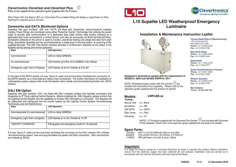
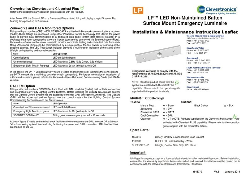
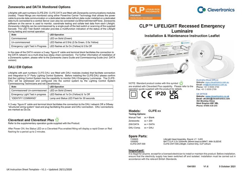
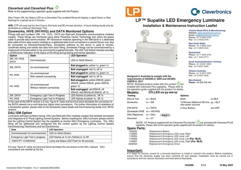
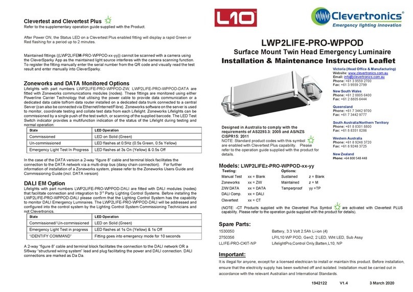
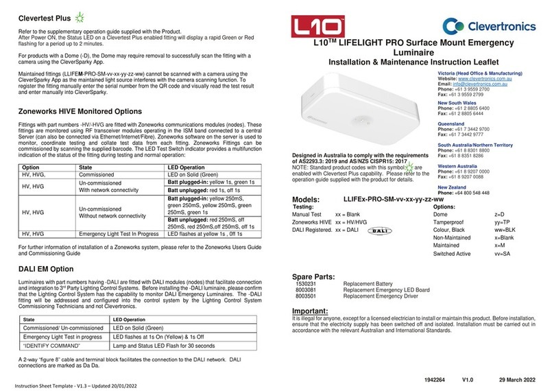
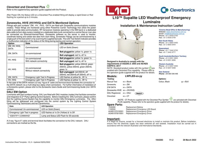
Clevertest and Clevertest Plus
Refer to the supplementary operation guide supplied with the Product.
After Power ON, the Status LED on a Clevertest Plus enabled fitting will display a rapid Green or Red
flashing for a period up to 2 minutes.
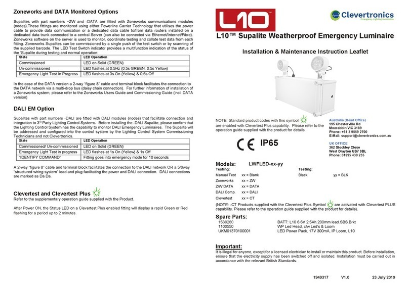
Zoneworks, HIVE and DATA Monitored Options
Fittings with part numbers -ZW, -HV/-HVG, -DATA are fitted with Zoneworks communications modules
(nodes). These fittings are monitored using either Powerline Carrier Technology that utilize the power
cable to provide data communication, RF transceiver modules operating in the ISM band or a dedicated
data cable to/from data routers installed on a dedicated data trunk connected to a central Server (can
also be connected via Ethernet/Internet/Fibre). Zoneworks software on the server is used to monitor,
coordinate testing and collate test data from each fitting. Zoneworks Fittings can be commissioned by
a single push of the test switch or by scanning the supplied barcode. The LED Test Switch indicator
provides a multifunction indication of the status of the fitting during testing and normal operation:
Option
State
LED Operation
ZW, HV, HVG,
DATA
Commissioned LED on Solid (Green)
ZW, DATA Un-commissioned Batt plugged-in: yellow 1s, green 1s
Batt unplugged: red 1s, off 1s
HV, HVG
Un-commissioned
With network connectivity
Batt plugged-in: yellow 1s, green 1s
Batt unplugged: red 1s, off 1s
HV, HVG Un-commissioned
Without network connectivity
Batt plugged-in: yellow 250mS,
green 250mS, yellow 250mS, green
250mS, green 1s
Batt unplugged: red 250mS, off
250mS, red 250mS,off 250mS, off 1s
ZW, DATA
Emergency Light Test In
Progress LED flashes at yellow 5s , 0ff 1s
HV, HVG
Emergency Light Test In
Progress
LED flashes at yellow 1s , 0ff 1s
In the case of the DATA version a 2-way “figure 8” cable and terminal block facilitates the connection
to the DATA network via a multi-drop bus (daisy chain connection). For further information of
installation of a Zoneworks system, please refer to the Zoneworks Users Guide and Commissioning
Guide (incl. DATA version)
DALI EM Option
Luminaires with part numbers having -DALI are fitted with DALI modules (nodes) that facilitate connection
and integration to 3rd Party Lighting Control Systems. Before installing the -DALI luminaire, please confirm
that the Lighting Control System has the capability to monitor DALI Emergency Luminaires. The -DALI
fitting will be addressed and configured into the control system by the Lighting Control System
Commissioning Technicians and not Clevertronics.
State
LED Operation
Commissioned/ Un-commissioned LED on Solid (Green)
Emergency Light Test in progress LED flashes at 1s On (Yellow) & 1s Off
“IDENTIFY COMMAND” Lamp and Status LED Flash for 30 seconds
A 2-way “figure 8” cable and terminal block facilitates the connection to the DALI network. DALI
connections are marked as Da Da.
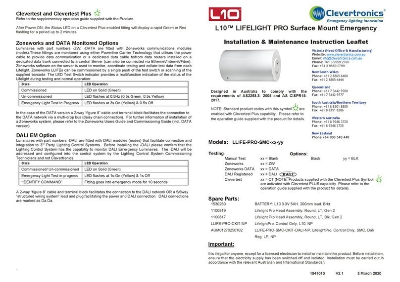
L10™ LIFELIGHT PRO Surface Mount
Emergency
Installation & Maintenance Instruction Leaflet
Designed in Australia to comply with the requirements
of AS2293.3: 2005 and AS CISPR15: 2017.
NOTE: Standard product codes with this symbol are
enabled with Clevertest Plus capability. Please refer to the
operation guide supplied with the product for details.
Victoria (Head Office & Manufacturing)
Website: www.clevertronics.com.au
Email: info@clevertronics.com.au
Phone: +61 3 9559 2700
Fax: +61 3 9559 2799
New South Wales
Phone: +61 2 8805 6400
Fax: +61 2 8805 6444
Queensland
Phone: +61 7 3442 9700
Fax: +61 7 3442 9777
South Australia/Northern Territory
Phone: +61 8 8301 8800
Fax: +61 8 8351 8286
Western Australia
Phone: +61 8 9207 0000
Fax: +61 8 9207 0088
New Zealand
Phone: +64 800 548 448
Models: LLIFE-PRO-SMC-xx-yy
Testing
:
Options:
Manual Test
xx = Blank
Black
yy = BLK
Zoneworks
xx = ZW
Zoneworks DATA
xx = DATA
DALI Registered
xx = DALI
HIVE
xx = HV/HVG
Clevertest
xx = CT (NOTE: Products supplied with the Clevertest Plus Symbol
are
activated with Clevertest PLUS capability. Please refer to the
operation guide supplied with the product for details).
Spare Parts:
1530230
Replacement Battery
1100869
Replacement Emergency LED
1100872
Replacement Emergency LED (-BLK)
AUM01370210001
Replacement Emergency Driver
Important:
It is illegal for anyone, except for a licensed electrician to install or maintain this product. Before installation,
ensure that the electricity supply has been switched off and isolated. Installation must be carried out in
accordance with the relevant Australian and International Standards.
1942306
V1.4
20 May 2022
Installation:
This Lifelight Pro Cylindrical Surface Mount Emergency Luminaire can be installed on solid or T-BAR
ceilings or used to replace an existing unit.
•Locate the installation position.
•Refer Images and Dimensions below for the Cut-out Hole and other dimensions.
•Pre-drill mounting holes.
•Mount base plate and use suitable fixings to secure the base plate into the pilot holes.
•Bring in supply cables via the rear entry hole.
•Terminate the supply cables to the L, N & E terminals (in the case of the –DALI or –DATA fittings
terminate the DALI or DATA cable to the terminals marked Da Da or DATA).
•Install the cylindrical top cover, containing the control gear, ensuring to reconnect the control gear
assembly to the connector from the supply terminal block.
•Ensure the Battery is connected.
•Screw the cover to the base plate.
•For HIVE version please install provided antenna on the side.
•If the CTP capabilities are activated, please affix the CTP status label to a visible surface and Four
Segment Marking on the product will include an ‘’F’’ in third segment block.
Networking:
When installing the product on a monitored network, (ZONEWORKS, DATA, HIVE, DALI) simply insert
the relevant Smart Node PCA.
Images and Dimensions:
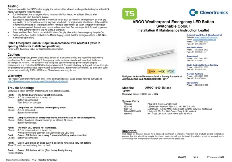
Testing:
When the Lifelight Pro Cylindrical Surface Mount Emergency Luminaire unit is connected to the un-
switched active, it must be allowed to charge the battery for at least 24 hours. The emergency lamp only
illuminates during a power fail. Conduct the following tests:
•The emergency lamp must illuminate for at least 2 hours after disconnection from the mains. The
results of all tests are required to be recorded in a service logbook, which is to be kept on-site at all
times. If the unit fails to illuminate for the requisite time, remedial action must be taken to repair the
situation and once completed, the unit must pass a subsequent test.
•Press and hold Test Button or switch Off Mains Supply, check that the emergency lamp is On.
•Release the Test Button or Switch On Mains Supply, check that the emergency lamp is Off (Non-
maintained operation).
Below are a list of common problems and their possible causes:
Fault: The Green LED indicator is not illuminated.
Check: A.C. is connected and is turned on.
Battery is connected.
Test Switch for damage.
Fault: Lamp does not illuminate in emergency mode.
Check: A.C. is connected.
Lamp is correctly inserted.
Battery is connected
Fault: Lamp illuminates in emergency mode, but only stays on for a short period.
Check: Battery has been allowed to charge for at least 24 hours.
Battery for damage.
Rated Emergency Lumen Output in accordance with AS2293.1 (refer
to spacing tables for installation positions):
Refer to the Technical Label for classification information.
Caution:
On many building sites, power circuits may be cut off in an uncontrolled and repetitive basis during
construction. As a result, any Exit & Emergency Units, on these circuits, will have their batteries
discharged or “cycled”. The battery in this fitting has been selected to give excellent long-life
performance in a controlled AS2293 testing environment. Excessive battery cycling will reduce through-
life performance and may lead to premature battery failure. Battery warranty claims, as a result of such
abuse, are specifically EXCLUDED from Clevertronics warranty terms.
Warranty:
For Product Warranty information and Terms and Conditions of Sales please refer to our website
http://clevertronics.com.au/terms-conditions-sale-australia-nz/

Other Clevertronics Lantern manuals

Clevertronics L10 LIFELIGHT PRO Manual

Clevertronics

Clevertronics L10 LIFELIGHT PRO Manual

Clevertronics Supalite L10 LWFLED Series Technical specifications

Clevertronics

Clevertronics Supalite L10 LWFLED Series Technical specifications

Clevertronics ARGO-1500-EM Series Installation and operating instructions

Clevertronics

Clevertronics ARGO-1500-EM Series Installation and operating instructions

Clevertronics L10 LIFELIGHT PRO LLIFE-PRO-SMC Series Installation and operating instructions

Clevertronics

Clevertronics L10 LIFELIGHT PRO LLIFE-PRO-SMC Series Installation and operating instructions

Clevertronics LP CBS2N Series Technical specifications

Clevertronics

Clevertronics LP CBS2N Series Technical specifications

Clevertronics CLP LIFELIGHT CLIFE Series Maintenance and service guide

Clevertronics

Clevertronics CLP LIFELIGHT CLIFE Series Maintenance and service guide

Clevertronics LP Supalite CFLLED Series Installation and operating instructions

Clevertronics

Clevertronics LP Supalite CFLLED Series Installation and operating instructions

Clevertronics L10 LWP2LIFE-PRO-WPPOD Series Installation and operating instructions

Clevertronics

Clevertronics L10 LWP2LIFE-PRO-WPPOD Series Installation and operating instructions

Clevertronics LP Supalite CFLLED Series Installation and operating instructions

Clevertronics

Clevertronics LP Supalite CFLLED Series Installation and operating instructions

Clevertronics Argonaut PRO ARGOPRO-1200 Series Installation and operating instructions

Clevertronics

Clevertronics Argonaut PRO ARGOPRO-1200 Series Installation and operating instructions

Clevertronics L10 LIFELIGHT PRO-SM Series User manual

Clevertronics

Clevertronics L10 LIFELIGHT PRO-SM Series User manual

Clevertronics L10 LWFLED Maintenance and service guide

Clevertronics

Clevertronics L10 LWFLED Maintenance and service guide

Clevertronics ARGO-600 EM Series Installation and operating instructions

Clevertronics

Clevertronics ARGO-600 EM Series Installation and operating instructions

Clevertronics L10 Supalite LWFLED Series Instruction Manual

Clevertronics

Clevertronics L10 Supalite LWFLED Series Instruction Manual

Clevertronics Argonaut Square ARGOSQ Series Installation and operating instructions

Clevertronics

Clevertronics Argonaut Square ARGOSQ Series Installation and operating instructions

Popular Lantern manuals by other brands

Coleman 4D XPS How to use

Coleman

Coleman 4D XPS How to use

Maxim Lighting Balboa VX 40162GFCO manual

Maxim Lighting

Maxim Lighting Balboa VX 40162GFCO manual

Vision Luminator LM400+ Series Installation

Vision

Vision Luminator LM400+ Series Installation

Allen + Roth 39508 manual

Allen + Roth

Allen + Roth 39508 manual

Teckentrup 1799004779 Assembly instructions

Teckentrup

Teckentrup 1799004779 Assembly instructions

MediaShop M35707 Instructions for use

MediaShop

MediaShop M35707 Instructions for use

esotec Trendy Using instructions

esotec

esotec Trendy Using instructions

Coleman 5312 Series user manual

Coleman

Coleman 5312 Series user manual

BEGA 84 268 Instructions for use

BEGA

BEGA 84 268 Instructions for use

BEGA 88 303 Instructions for use

BEGA

BEGA 88 303 Instructions for use

Fulham Firehorse FH10-DUAL-500L Specification sheet

Fulham

Fulham Firehorse FH10-DUAL-500L Specification sheet

Traxon Allegro Washer AC Accessories Mounting Guide

Traxon

Traxon Allegro Washer AC Accessories Mounting Guide

DW Windsor Series installation instructions

DW

DW Windsor Series installation instructions

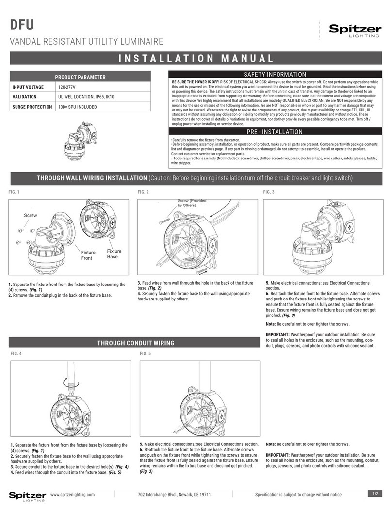
Spitzer LIGHTING DFU installation manual

Spitzer LIGHTING

Spitzer LIGHTING DFU installation manual

GE Versaflood III instructions

GE

GE Versaflood III instructions

MUNDUS Silva instruction manual

MUNDUS

MUNDUS Silva instruction manual

High End Systems StudioPix Pixelation Luminaire user manual

High End Systems

High End Systems StudioPix Pixelation Luminaire user manual

AEL 115 Series Installation & maintenance instructions

AEL

AEL 115 Series Installation & maintenance instructions

manuals.online logo
manuals.online logoBrands
  • About & Mission
  • Contact us
  • Privacy Policy
  • Terms and Conditions

Copyright 2025 Manuals.Online. All Rights Reserved.