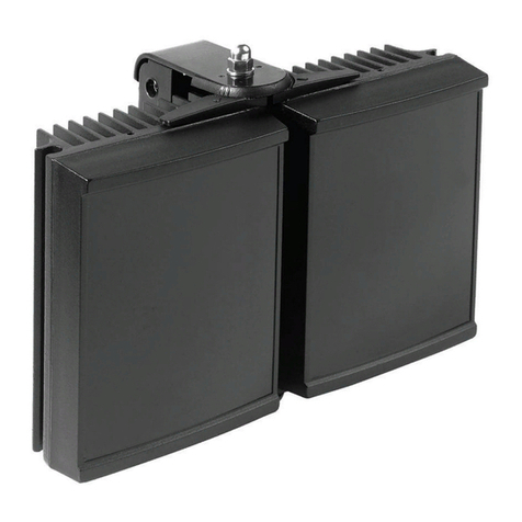
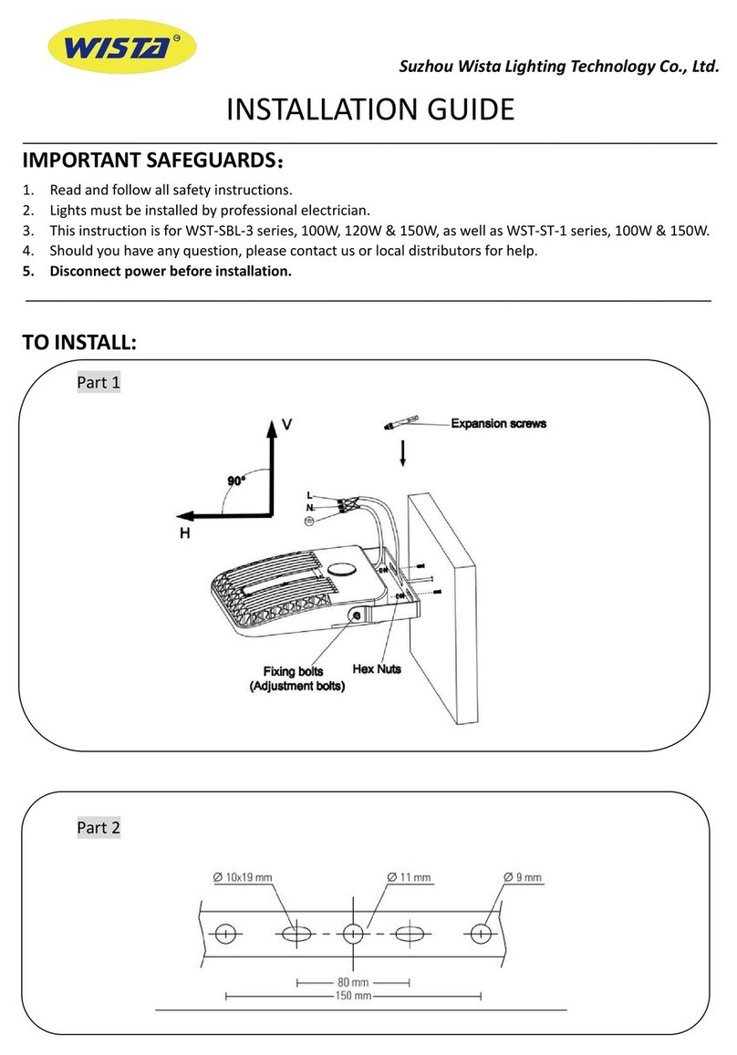
Clevertronics ARGO-600 EM Series Installation and operating instructions
Other Clevertronics Lantern manuals

Clevertronics
Clevertronics Argonaut PRO ARGOPRO-1200 Series Installation and operating instructions

Clevertronics
Clevertronics ARGO-1500-EM Series Installation and operating instructions
Clevertronics
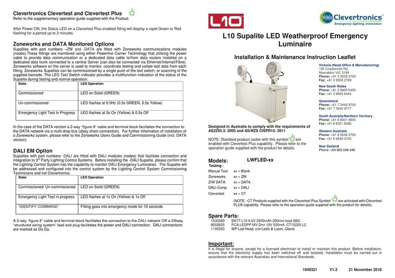
Clevertronics Supalite L10 LWFLED Series Technical specifications

Clevertronics
Clevertronics L10 LWP2LIFE-PRO-WPPOD Series Installation and operating instructions
Clevertronics
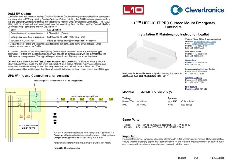
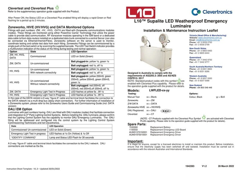
Clevertronics L10 LIFELIGHT PRO Manual
Clevertronics
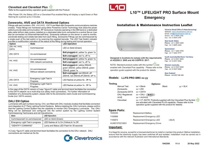
Clevertronics L10 Supalite LWFLED Series Instruction Manual
Clevertronics
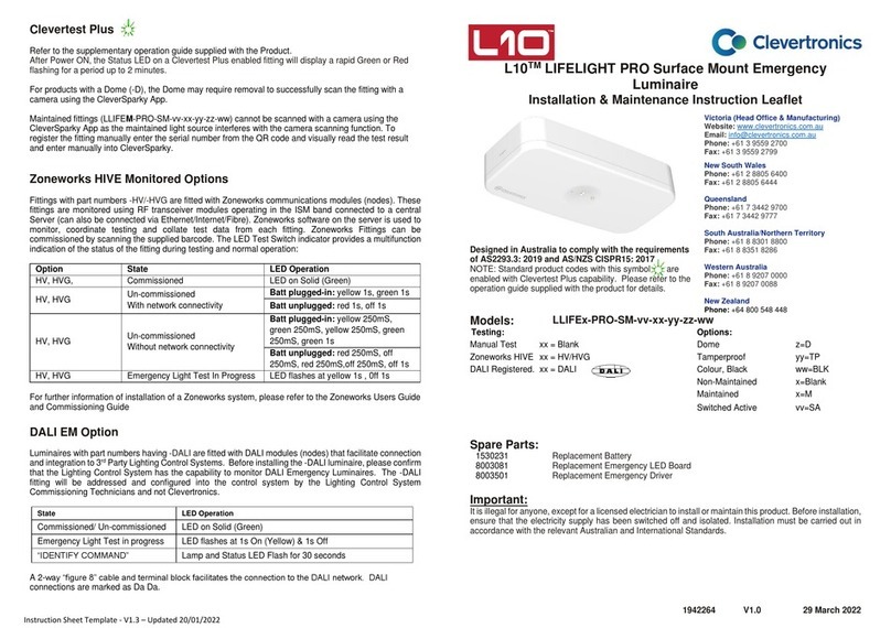
Clevertronics L10 LIFELIGHT PRO LLIFE-PRO-SMC Series Installation and operating instructions
Clevertronics
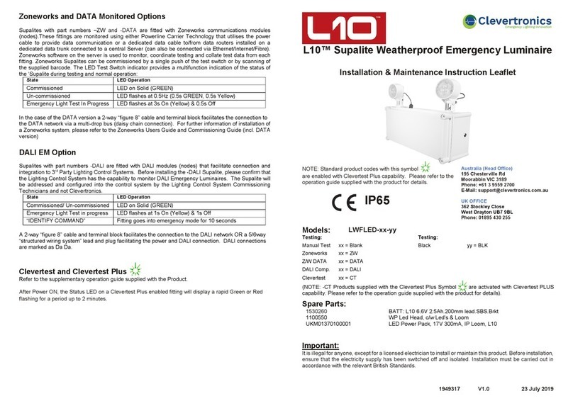
Clevertronics L10 LIFELIGHT PRO-SM Series User manual
Clevertronics
Clevertronics L10 LWFLED Maintenance and service guide

Clevertronics
Clevertronics LP Supalite CFLLED Series Installation and operating instructions
Clevertronics
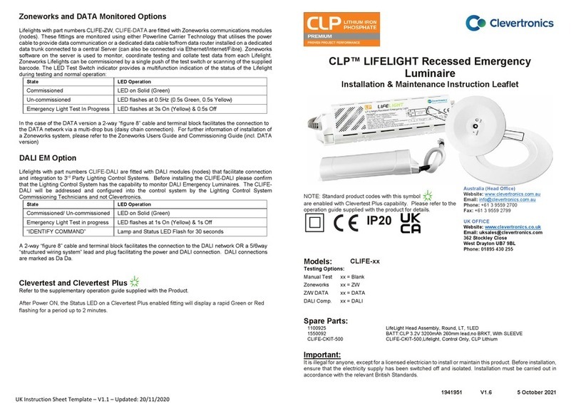
Clevertronics CLP LIFELIGHT CLIFE Series Maintenance and service guide

Clevertronics
Clevertronics LP CBS2N Series Technical specifications

Clevertronics
Clevertronics LP Supalite CFLLED Series Installation and operating instructions

Clevertronics
Clevertronics L10 LIFELIGHT PRO LLIFE-PRO-SMC Series Installation and operating instructions

Clevertronics
Clevertronics Argonaut Square ARGOSQ Series Installation and operating instructions
Popular Lantern manuals by other brands

Endon
Endon Burford Bollard instruction manual
Sealite
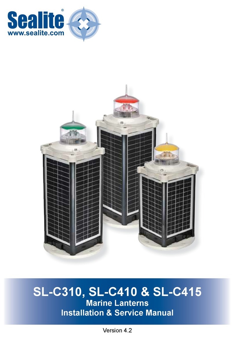
Sealite SLC310 Installation & service manual
Larson Electronics
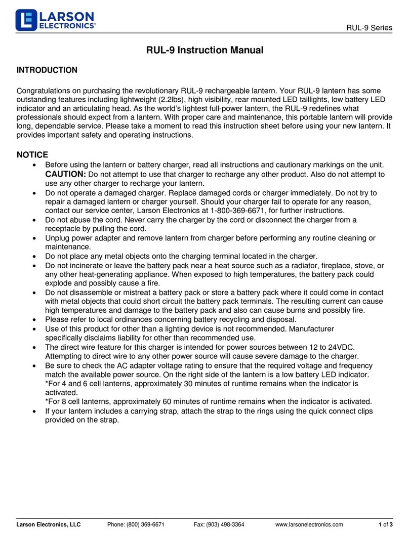
Larson Electronics RUL-9 Series instruction manual

ROBENS
ROBENS KIRK instructions

LED's light
LED's light OUTDOOR Series instruction manual
Maxim Lighting
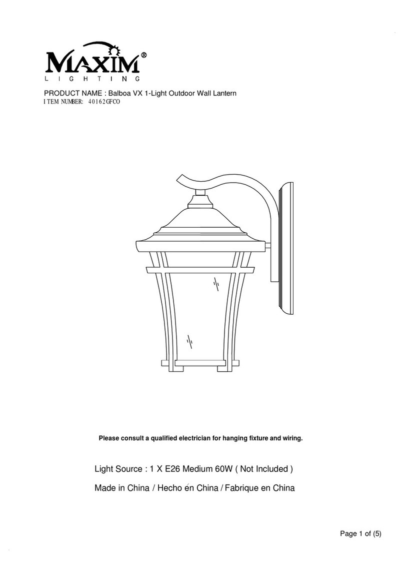
Maxim Lighting Balboa VX 40162GFCO manual

Heitronic
Heitronic 500047 Installation and operating instructions
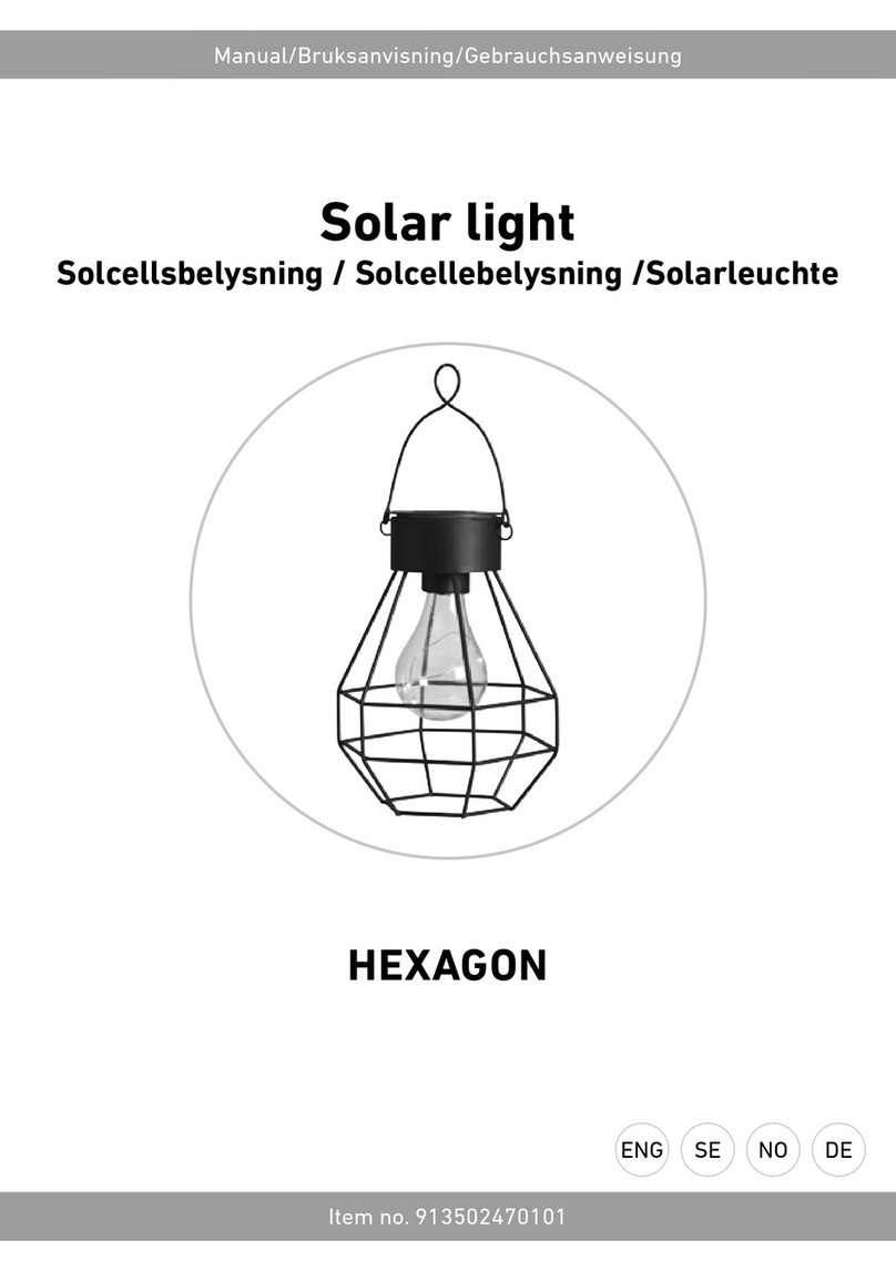
RUSTA
RUSTA HEXAGON manual

Quoizel
Quoizel Bain BAN9011K Assembly instruction sheet

Signature Hardware
Signature Hardware Burruss EL2501ASGR/CMNT quick start guide

Intermatic
Intermatic Malibu LZ11771HK instructions

MELINERA
MELINERA 291041 Assembly, operating and safety instructions


