manuals.online logo
Brands
  1. Home
  2. •
  3. Brands
  4. •
  5. Cree
  6. •
  7. Lantern
  8. •
  9. Cree 228 Series User manual

Cree 228 Series User manual

INSTALLATION INSTRUCTIONS
228 SERIES
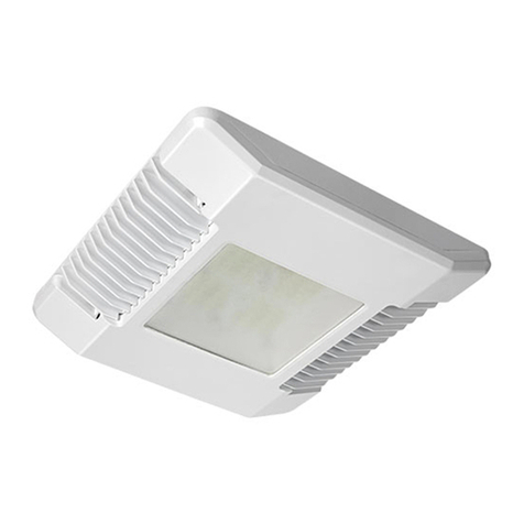
LED RECESSED CANOPY LUMINAIRE
Includes: XCTA SERIES
CI372X01R1
Page 1 of 2
TO INSTALL:
CAUTIONS
F1
LUMINAIRE INSTALLATION
STEP 1:
Cut an appropriate sized hole in the canopy based on the
following table.
LED COUNT CUTOUT DIMENSION TOLERANCE
30 LED 7 - 3/8” BY 11 - 3/8” + 1/16”
- 1/32”
60 LED 7 - 3/8” BY 16 - 1/8”
90 LED 7 - 3/8” BY 20 - 15/16”
STEP 2:
Insert luminaire through opening and place on canopy
channel as shown in Figure 1
STEP 3:
Position luminaire in opening and secure in place with
(2) retention clips by rotating clips over canopy and
tightening screws. See Figure 2.
STEP 4:
Wire luminaire per “Electrical Connections” section.
STEP 5:
On the bottom side of the canopy, install the trim frame
over the luminaire and secure using the retained screws.
Frame must be in contact with canopy around entire
perimeter. See Figure 3.
IMPORTANT SAFEGUARDS
When using electrical equipment, basic safety precautions should always be followed including the following:
READ AND FOLLOW ALL SAFETY INSTRUCTIONS
1. To avoid the possibility of electrical shock, turn off power supply before installation or servicing.
2. This luminaire must be installed in accordance with the NEC or your local electrical code. If you are not familiar
with these codes and requirements, consult a qualified electrician.
3. Luminaires that are UL Listed for Wet LocationS are intended for typical outdoor use, including rain and snow.
These luminaires are not intended to be submerged or subjected to standing water for long periods of time.
4. This luminaire is not thermally protected and is intended for installation in an outdoor canopy or marquee.
5. Damage to fixture will result when improper voltage is applied. Verify fixture is suitable for supply voltage by
checking electrical label on fixture.
NOTE: Some products may require marked spacings for installation, refer to luminaire label for specific spacing
requirements.
SAVE THESE INSTRUCTIONS FOR FUTURE REFERENCE
F2
SENSOR DOOR
F3
CI372X01R1
Page 2 of 3
30 LED LUMINAIRE
Switch
Position
1050mA Max 700mA Max 525mA Max
Drive
Current
Power
Multiplier
Lumen
Multiplier
Drive
Current
Power
Multiplier
Lumen
Multiplier
Drive
Current
Power
Multiplier
Lumen
Multiplier
1525 0.44 0.59 350 0.49 0.55 175 0.36 0.54
2 600 0.51 0.66 425 0.60 0.66 225 0.45 0.60
3675 0.59 0.74 475 0.67 0.72 275 0.55 0.70
4750 0.65 0.79 525 0.73 0.79 325 0.64 0.76
5 825 0.72 0.85 550 0.78 0.82 350 0.67 0.82
6 900 0.78 0.90 575 0.81 0.84 375 0.72 0.88
7950 0.83 0.93 625 0.88 0.91 425 0.83 0.92
8 1000 0.87 0.97 650 0.92 0.92 475 0.92 0.96
9 1050 1.00 1.00 700 1.00 1.00 525 1.00 1.00
60 LED LUMINAIRE
Switch
Position
900mA Max 700mA Max 525mA Max 350mA Max
Drive
Current
Power
Multiplier
Lumen
Multiplier
Drive
Current
Power
Multiplier
Lumen
Multiplier
Drive
Current
Power
Multiplier
Lumen
Multiplier
Drive
Current
Power
Multiplier
Lumen
Multiplier
1350 0.40 0.46 350 0.49 0.55 175 0.36 0.39 175 0.49 0.55
2 425 0.52 0.54 425 0.60 0.66 225 0.45 0.51 213 0.60 0.66
3475 0.53 0.60 475 0.67 0.72 275 0.55 0.63 238 0.67 0.72
4525 0.58 0.65 525 0.73 0.79 325 0.64 0.70 263 0.73 0.79
5 600 0.67 0.72 550 0.78 0.82 350 0.67 0.76 275 0.78 0.82
6675 0.75 0.79 575 0.81 0.84 375 0.72 0.81 288 0.81 0.84
7750 0.83 0.87 625 0.88 0.91 425 0.83 0.87 313 0.88 0.91
8 825 0.92 0.92 650 0.92 0.92 475 0.92 0.94 325 0.92 0.92
9 900 1.00 1.00 700 1.00 1.00 525 1.00 1.00 350 1.00 1.00
90 LED LUMINAIRE
Switch
Position
700mA Max 525mA Max 350mA Max
Drive
Current
Power
Multiplier
Lumen
Multiplier
Drive
Current
Power
Multiplier
Lumen
Multiplier
Drive
Current
Power
Multiplier
Lumen
Multiplier
1350 0.49 0.55 175 0.36 0.39 175 0.49 0.55
2 425 0.60 0.66 225 0.45 0.51 213 0.60 0.66
3475 0.67 0.72 275 0.55 0.63 238 0.67 0.72
4525 0.73 0.79 325 0.64 0.70 263 0.73 0.79
5 550 0.78 0.82 350 0.67 0.76 275 0.78 0.82
6575 0.81 0.84 375 0.72 0.81 288 0.81 0.84
7 625 0.88 0.91 425 0.83 0.87 313 0.88 0.91
8 650 0.92 0.92 475 0.92 0.94 325 0.92 0.92
9700 1.00 1.00 525 1.00 1.00 350 1.00 1.00
FIELD ADJUSTABLE DIMMING
STEP 1:
This luminaire is provided
with field adjustable dimming.
Luminaires leave the factory
adjusted to the maximum
setting which is Position 9 as
shown in Figure 6.
STEP 2:
Locate the luminaires electrical
label and verify the luminaires
LED count and the maximum
current available.
STEP 3:
The Dimming module is located
inside the luminaire. Open
the sensor door by loosening
the (4) self retained screws
and carefully lower the door.
See Figure 3 on page 1.
STEP 4:
Establish the desired drive
current on the following tables
and turn the switch to the
correlating position on the
Dimming Control Module.
STEP 5:
Adjust the Dimming Module to
the selected position, replace
the door ensuring no wires are
pinched. Tighten the screws
that were loosened in Step 3.
F6
CI372X01R1
Page 3 of 3
The information in this document in subject to change without notice.
Visit website for patents that cover these products: Patent http://www.cree.com/patents
Visit website for warranties that cover Cree® BetaLED® Technology products:
Warranties http://www.cree.com/lighting/products/warranty
ELECTRICAL CONNECTIONS
STEP 1:
Remove Junction Box Cover.
STEP 2:
Remove one of the plugs from the Junction Box and attach
incoming supply conduit (supplied by others) with a listed liquid-
tight conduit connector.
STEP 3:
With the power off, connect branch circuit conductors to LED
driver input leads.
STEP 4:
Tighten all liquid-tight conduit connectors.
STEP 5:
Using 90°C minimum rated wire connectors, make the following
electrical connections within the Junction Box:
a. Connect the black fixture lead to the voltage supply lead or
Hot 1 (for 208/240V wiring).
b. Connect the white fixture lead to the neutral supply lead or
Hot 2 (for 208/240V wiring).
c. Connect the green or green/yellow ground lead to the
green lead.
d. If Dimming is an option; connect the violet dimming
positive lead to the supply dimming positive lead.
e. If Dimming is an option; connect the grey dimming negative
lead to the supply dimming negative lead.

This manual suits for next models

1

Other Cree Lantern manuals

Cree CS14 User manual

Cree

Cree CS14 User manual

Cree RUL Series User manual

Cree

Cree RUL Series User manual
Cree XSP Series User manual

Cree

Cree XSP Series User manual
Cree 228 Series User manual

Cree

Cree 228 Series User manual
Cree CR Series User manual

Cree

Cree CR Series User manual
Cree DPT Series User manual

Cree

Cree DPT Series User manual
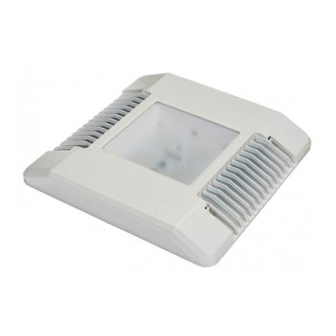
Cree CPY250 User manual

Cree

Cree CPY250 User manual
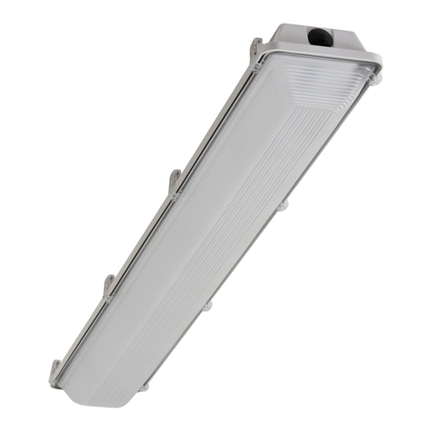
Cree WS Series User manual

Cree

Cree WS Series User manual
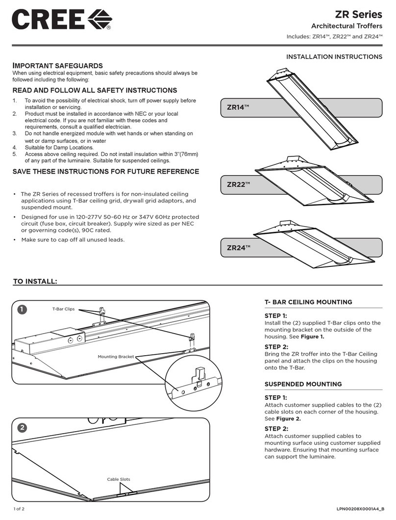
Cree ZR Series User manual

Cree

Cree ZR Series User manual
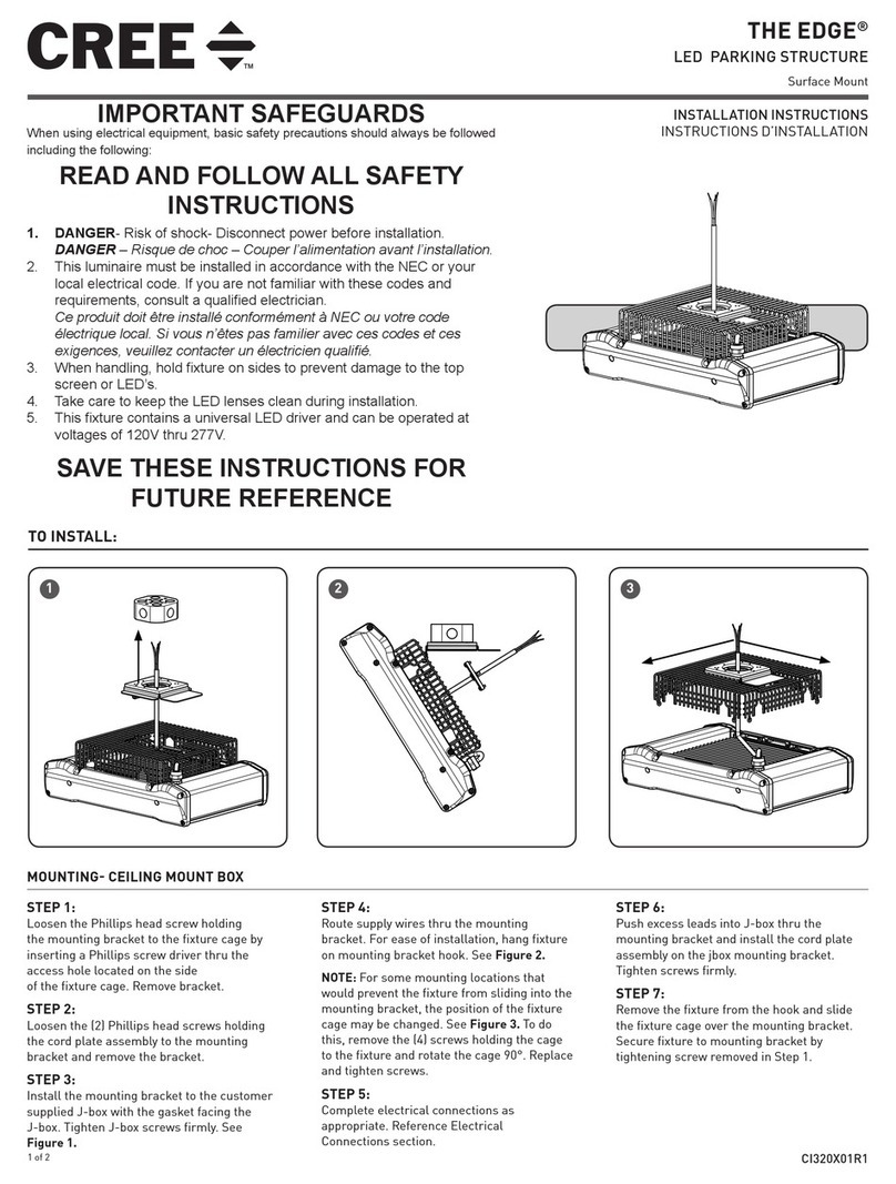
Cree THE EDGE Series User manual

Cree

Cree THE EDGE Series User manual
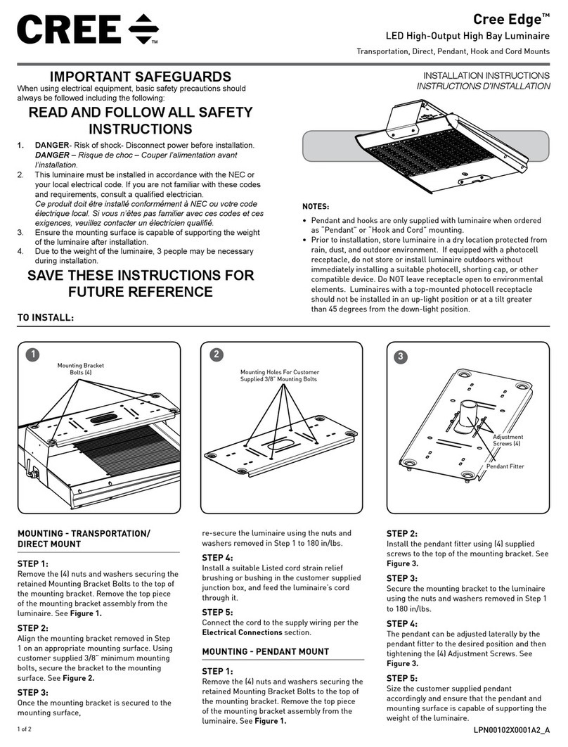
Cree Edge User manual

Cree

Cree Edge User manual

Cree RUL Series User manual

Cree

Cree RUL Series User manual

Cree KBL Series Installation instructions
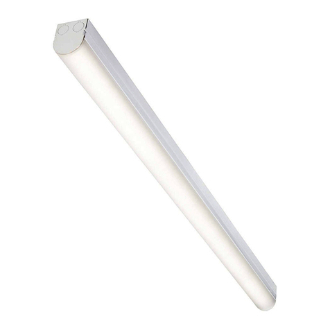
Cree

Cree KBL Series Installation instructions

Cree LS8 User manual

Cree

Cree LS8 User manual

Cree Essentia FP Series User manual

Cree

Cree Essentia FP Series User manual

Cree XRAAF Series User manual

Cree

Cree XRAAF Series User manual
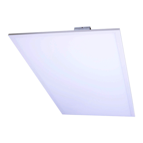
Cree C-Lite C-TR-A-FP User manual

Cree

Cree C-Lite C-TR-A-FP User manual
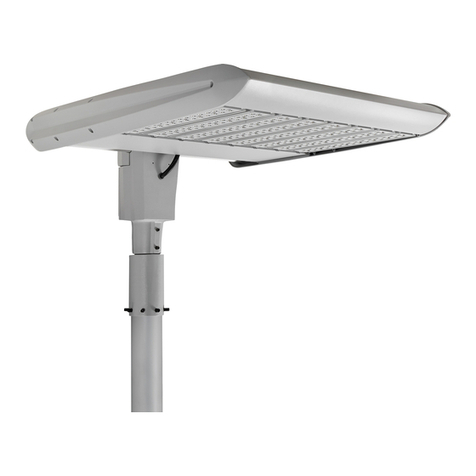
Cree XAK Series User manual

Cree

Cree XAK Series User manual
Cree IG Series User manual

Cree

Cree IG Series User manual
Cree Edge XAKE Series User manual

Cree

Cree Edge XAKE Series User manual

Cree CPY Series User manual

Cree

Cree CPY Series User manual

Cree FLEX Series User manual

Cree

Cree FLEX Series User manual

Popular Lantern manuals by other brands

Zephir ZHL116 instruction manual

Zephir

Zephir ZHL116 instruction manual

Wetelux 874256 instruction manual

Wetelux

Wetelux 874256 instruction manual

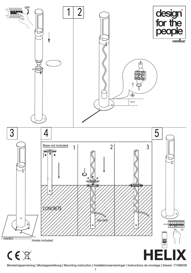
nordlux HELIX 77498038 Mounting instruction

nordlux

nordlux HELIX 77498038 Mounting instruction

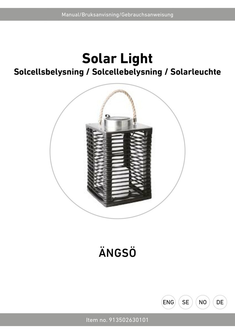
RUSTA ANGSO manual

RUSTA

RUSTA ANGSO manual

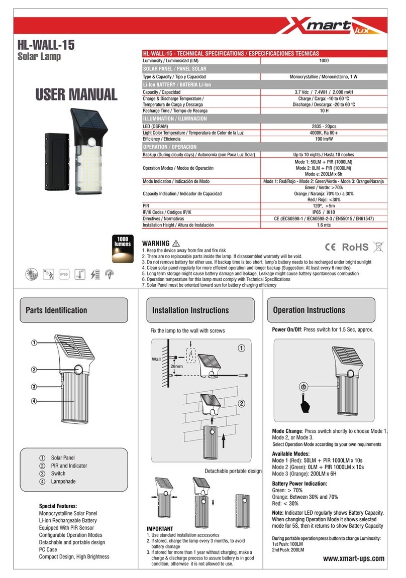
Xmart HL-WALL-15 user manual

Xmart

Xmart HL-WALL-15 user manual

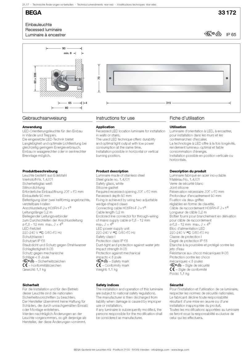
BEGA 33 172 Instructions for use

BEGA

BEGA 33 172 Instructions for use

ML Accessories RW5WW Installation & maintenance manual

ML Accessories

ML Accessories RW5WW Installation & maintenance manual

BEGA 24 210 Instructions for use

BEGA

BEGA 24 210 Instructions for use
Teknoware TWT17 Series Installation and maintenance manual
Teknoware

Teknoware TWT17 Series Installation and maintenance manual

Zumtobel ARC3 LED 3CD Series Instructions for mounting

Zumtobel

Zumtobel ARC3 LED 3CD Series Instructions for mounting

olympia electronics SLD-28/DZ quick start guide
olympia electronics

olympia electronics SLD-28/DZ quick start guide

Robus SOL RSO240P-01 quick start guide
Robus

Robus SOL RSO240P-01 quick start guide

CREE LIGHTING KBL Series installation instructions

CREE LIGHTING

CREE LIGHTING KBL Series installation instructions

Signature Hardware AMBLER 434134 Installation
Signature Hardware

Signature Hardware AMBLER 434134 Installation

Fusion 24812 Assembly instructions

Fusion

Fusion 24812 Assembly instructions
HYPERLITE WILL Series instruction manual

HYPERLITE

HYPERLITE WILL Series instruction manual

Coleman 4D XPS How to use

Coleman

Coleman 4D XPS How to use

I-VALO HITE LED Operation and maintenance instructions

I-VALO

I-VALO HITE LED Operation and maintenance instructions

manuals.online logo
manuals.online logoBrands
  • About & Mission
  • Contact us
  • Privacy Policy
  • Terms and Conditions

Copyright 2025 Manuals.Online. All Rights Reserved.