manuals.online logo
Brands
  1. Home
  2. •
  3. Brands
  4. •
  5. Cree
  6. •
  7. Lantern
  8. •
  9. Cree XAK Series User manual

Cree XAK Series User manual

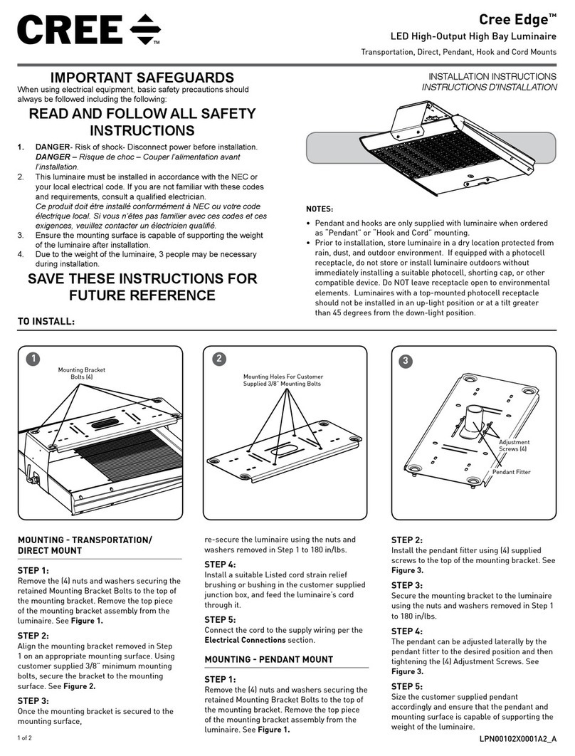
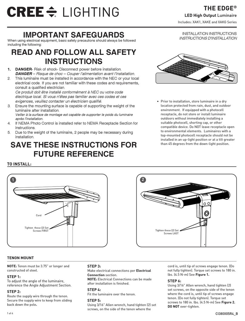
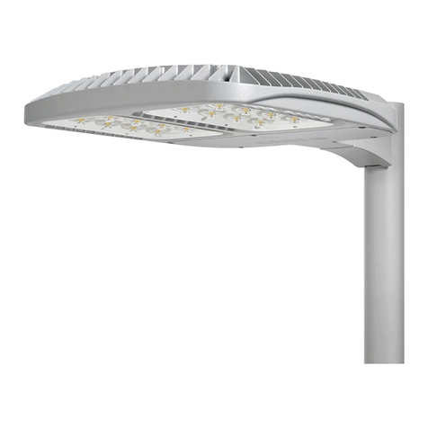
Cree Edge™
LED High Output Luminaire
Includes: XAK Series
1 of 3 CI380X01R5
INSTALLATION INSTRUCTIONS
INSTRUCTIONS D’INSTALLATION
TO INSTALL:
TENON MOUNT
NOTE: Tenon must be 3.75" or taller.
STEP 1:
To adjust the angle of the luminaire,
reference the Angle Adjustment Section.
STEP 2:
Remove (3) 8-32 Phillips head screws that
secure the Mounting Clamp Cover to the
mounting clamp and set aside. See Figure 1.
STEP 3:
Remove the mounting clamp cover exposing
the wire connections and set aside. See
Figure 1.
STEP 4:
Remove the terminal block bracket by
removing the (1) 8-32 Phillips head screw and
set aside. See Figure 1.
STEP 5:
Route the supply wire up the vertical tenon
and through the center hole of the adjustable
slip fitter. Secure the supply wire to keep from
sliding back down the pole. See Figure 2.
STEP 6:
Make electrical connections per Electrical
Connection section.
STEP 7:
Replace terminal block bracket into wiring
compartment removed in Step 4.
STEP 8:
Replace cover and cover gasket using the (3)
8-32 pan head screws remove in Step 2.
STEP 9:
Fit the Adjustable Slip Fitter over the vertical
tenon making sure the fitter is centered on the
tenon.
STEP 10:
Using 3/16" Allen wrench, hand tighten set
screws in a crossing pattern around tenon
until tip of screws engage tenon. (Do not fully
tighten). Torque set screws to 40 in. lbs. (4.5
N-m) See Cross Pattern Tightening Chart.
STEP 11:
Repeat torque set screws to 80 in. lbs. (9.0
N-m) following Cross Pattern chart.
STEP 12:
Repeat torque set screws to 120-130 in. lbs.
(13.5-14.5 N-m) following Cross Pattern chart.
DO NOT over-tighten.
*
*
*
*
*Bottom row of set-screws
1Mounting
Clamp Cover
Terminal
Block Bracket
Mounting
Clamp
Adjustable
Slip Fitter
Tenon
2
IMPORTANT SAFEGUARDS
When using electrical equipment, basic safety precautions should always be followed
including the following:
READ AND FOLLOW ALL SAFETY
INSTRUCTIONS
1. DANGER- Risk of shock- Disconnect power before installation.
DANGER – Risque de choc – Couper l’alimentation avant l’installation.
2. This luminaire must be installed in accordance with the NEC or your local electrical
code. If you are not familiar with these codes and requirements, consult a qualied
electrician.
Ce produit doit être installé conformément à NEC ou votre code électrique local.
Si vous n’êtes pas familier avec ces codes et ces exigences, veuillez contacter un
électricien qualié.
3. If NEMA® Photo Control is installed refer to NEMA® Receptacle Section for
instructions.
4. Ensure the mounting surface is capable of supporting the weight of the luminaire
after installation.
Veiller à la surface de montage est capable de supporter le poids du luminaire
après l’installation
5. Due to the weight of the luminaire, 2 people may be necessary during installation.
6. WARNING: This luminaire is intended to be mounted to a vertical tenon only.
SAVE THESE INSTRUCTIONS FOR
FUTURE REFERENCE
• Prior to installation, store luminaire in a dry location
protected from rain, dust, and outdoor environment.
If equipped with a photocell receptacle, do not store
or install luminaire outdoors without immediately
installing a suitable photocell, shorting cap, or
other compatible device. Do NOT leave receptacle
open to environmental elements. Luminaires with
a top-mounted photocell receptacle should not be
installed in an up-light position or at a tilt greater
than 45 degrees from the down-light position.
2 of 3 CI380X01R5
ANGLE ADJUSTMENT
STEP 1:
After the luminaire is installed, the angle of the
luminaire can be adjusted approximately 90° up or
down in 5° increments.
STEP 2:
To adjust the angle, loosen the four 3/8 – 16 X 1.5"
Socket Head Cap Screws located in the top section
of the Mounting Clamp using the provided 5/16” Hex
Wrench.
STEP 3:
Using the Angle Bracket, shown in Figure 3, as a
guide rotate the luminaire to the desired position and
retighten the screws loosened in Step 2 to 120 in.-lbs.
LATERAL ADJUSTMENT
STEP 1:
The position of the luminaire can also be adjusted
laterally. To adjust the Lateral position, loosen the four
3/8 – 16 X 1.5" Socket Head Cap Screws located in the
top section of the Mounting Clamp using the provided
5/16" Hex Wrench. See Figure 3.
STEP 2:
Remove the Angle Bracket and (2) screws and set aside.
See Figure 3
STEP 3:
The Angle Bracket can be secured using the existing
holes on the luminaire bar. Set the Mounting Clamp to
desired lateral adjustment using the following positions
on the bar (See Figure 4):
• Position 2 - Left justification.
• Position 4 - Center position (when angle
bracket is on the left side of the mounting
clamp).
• Position 5 - Center position (when angle
bracket is on the right side of the mounting
clamp).
• Position 7 - Right justification.
NOTE: Positions 1,3,6 and 8 will not be able to be used.
NOTE: Mounting two luminaires to a 24” Bullhorn
Tenon will require one luminaire mounted in position 2
and one luminaire mounted in position 7.
STEP 4:
Once desired position is achieved reinstall the Angle
Bracket using (2) screws that were removed in Step 2.
STEP 5:
Retighten screws that were loosened in Step 1 to 120
in-lbs.
NEMA® RECEPTACLE (OPTIONAL)
STEP 1:
DO NOT loosen/tighten pan head screws for the NEMA®
receptacle.
STEP 2:
Rotational adjustment of the photo control is tool-less.
STEP 3:
Engage/install photo control into NEMA® receptacle on
top of the fixture.
STEP 4:
Firmly rotate photo-control with its photo-eye
approximately in the ‘N’ north direction. Some photo-
controls operate best somewhere between NW and NE.
3
Mounting
Clamp
Angle
Bracket
Angle Markings
Socket Head
Cap Screws
Numbers on angle bracket are shown for illustration purpose
only. Actual bracket doesn’t show numbers.
4
4321 8765
Angle Bracket is Shown in Position 5 in This Illustration
Mounting Clamp
3 of 3 CI380X01R5
www.lighting.cree.com
© 2018 Cree, Inc. All rights reserved. For informational purposes only. Content is subject to change.
See http://lighting.cree.com/warranty for warranty and specifications. Cree®is a registered trademark, and the Cree logo and
Cree EdgeTM are trademarks of Cree, Inc. NEMA® is a registered trademark of the National Electrical Manufacturers Association.
FIELD ADJUSTABLE DIMMING - OPTIONAL
STEP 1:
This luminaire may be provided with field adjustable dimming.
Luminaires leave the factory adjusted to the maximum setting
which is Position 9 as shown in Figure 5.
STEP 2:
Locate the luminaires electrical label and verify the luminaires LED
count and the maximum current available.
STEP 3:
The Dimming module is located inside the Mounting Clamp
on the Terminal Block Bracket. Remove (3) 8-32 Phillips
head screws that secure the Mounting Clamp Cover to the
Mounting Clamp and set aside. See Figure 1 on page 1.
STEP 4:
Remove the mounting clamp cover exposing the wire connections
and set aside. See Figure 1 on page 1.
STEP 5:
Remove the terminal block bracket by removing the (1) 8-32 Phillips
head screw and set aside. See Figure 1 on page 1.
STEP 6:
Establish the desired input power multiplier by referring to the
product dimming spec sheet and turn the switch to the correlating
position.
STEP 7:
Adjust the Dimming Module to the selected position, replace the
terminal block bracket and the Mounting Clamp Cover ensuring no
wires are pinched and reinstall the screws that were removed in
Step 3.
5
ELECTRICAL CONNECTIONS
STEP 1:
Make the following Electrical Connections to supply cord:
a. For 120/277/347V connect the black fixture lead to the
voltage supply position of the terminal block or Hot 1 (for
208/240/480V wiring).
b. For 120/277/347V connect the white fixture lead to the
neutral supply position of the terminal block or Hot 2 (for
208/240/480V wiring).
c. Connect the green or green/yellow ground lead to the
green wire position of the terminal block.
d. If Dimming is an option; connect the violet dimming
positive lead to the supply dimming positive lead.
e. If Dimming is an option; connect the grey dimming
negative lead to the supply dimming negative lead
LINE
OR HOT 1
GREEN
LINE-BLACK
GROUND-GREEN
NEUTRAL-WHITE
DIM (-) GREY
DIM (+) VIOLET
NEUTRAL
OR HOT 2
VIOLET
GREY
SUPPLY WIRING
(DIMMING OPTIONAL)
LUMINAIRE
TERMINAL
BLOCK

This manual suits for next models

1

Other Cree Lantern manuals

Cree CPY250 User manual

Cree

Cree CPY250 User manual

Cree Edge User manual

Cree

Cree Edge User manual

Cree RUL Series User manual

Cree

Cree RUL Series User manual

Cree CPY Series User manual

Cree

Cree CPY Series User manual

Cree 228 Series User manual

Cree

Cree 228 Series User manual

Cree Edge XAKE Series User manual

Cree

Cree Edge XAKE Series User manual

Cree 228 Series User manual

Cree

Cree 228 Series User manual

Cree XSP Series User manual

Cree

Cree XSP Series User manual

Cree XRAAF Series User manual

Cree

Cree XRAAF Series User manual

Cree RUL Series User manual

Cree

Cree RUL Series User manual

Cree C-Lite C-TR-A-FP User manual

Cree

Cree C-Lite C-TR-A-FP User manual

Cree KBL Series Installation instructions

Cree

Cree KBL Series Installation instructions

Cree Essentia FP Series User manual

Cree

Cree Essentia FP Series User manual

Cree DPT Series User manual

Cree

Cree DPT Series User manual

Cree LS8 User manual

Cree

Cree LS8 User manual

Cree WS Series User manual

Cree

Cree WS Series User manual

Cree CS14 User manual

Cree

Cree CS14 User manual

Cree IG Series User manual

Cree

Cree IG Series User manual

Cree CR Series User manual

Cree

Cree CR Series User manual

Cree THE EDGE Series User manual

Cree

Cree THE EDGE Series User manual

Cree FLEX Series User manual

Cree

Cree FLEX Series User manual

Cree ZR Series User manual

Cree

Cree ZR Series User manual

Popular Lantern manuals by other brands

Velleman Perel Tools CSOL14 Mounting

Velleman

Velleman Perel Tools CSOL14 Mounting

WE-EF ETC130-FS LED Installation and maintenance instructions

WE-EF

WE-EF ETC130-FS LED Installation and maintenance instructions

Harbor Freight Tools 91771 Assembly and operating instructions

Harbor Freight Tools

Harbor Freight Tools 91771 Assembly and operating instructions

Trilux LUCEO SLIM ETDS LED operating instructions

Trilux

Trilux LUCEO SLIM ETDS LED operating instructions

WE-EF DLO200 Series Installation and maintenance instructions

WE-EF

WE-EF DLO200 Series Installation and maintenance instructions

Velvet Mini Power Series user manual

Velvet

Velvet Mini Power Series user manual

Up-shine Lighting UP-PL30120-27W-E Technical application guide

Up-shine Lighting

Up-shine Lighting UP-PL30120-27W-E Technical application guide

Kenroy Home VILLA PORTABLE POST LANTERN 93432 Use and care guide

Kenroy Home

Kenroy Home VILLA PORTABLE POST LANTERN 93432 Use and care guide

RUSTA 91301074 manual

RUSTA

RUSTA 91301074 manual

Craftmade Z9802 Mounting instructions

Craftmade

Craftmade Z9802 Mounting instructions

IKEA STRALA J2028 manual

IKEA

IKEA STRALA J2028 manual

Novah Solray Select III Installation

Novah

Novah Solray Select III Installation

BEGA 77 321 Instructions for use

BEGA

BEGA 77 321 Instructions for use

Endon Burford Bollard instruction manual

Endon

Endon Burford Bollard instruction manual

Quoizel NY8411K Assembly instruction sheet

Quoizel

Quoizel NY8411K Assembly instruction sheet

LUTEC TABLE CUBE 6908001331 user manual

LUTEC

LUTEC TABLE CUBE 6908001331 user manual

A. Mallios Pamal WP quick start guide

A. Mallios

A. Mallios Pamal WP quick start guide

unios LINEAR Series quick start guide

unios

unios LINEAR Series quick start guide

manuals.online logo
manuals.online logoBrands
  • About & Mission
  • Contact us
  • Privacy Policy
  • Terms and Conditions

Copyright 2025 Manuals.Online. All Rights Reserved.