manuals.online logo
Brands
  1. Home
  2. •
  3. Brands
  4. •
  5. Cree
  6. •
  7. Lantern
  8. •
  9. Cree CS14 User manual

Cree CS14 User manual

1 of 4 LPN00212X0003A8
CS Series With Cree SmartCast®Technology
CS14™, CS18™LED Linear Luminaire
8' and 4' Luminaires
INSTALLATION INSTRUCTIONS
INSTRUCTIONS D’INSTALLATION
• The CS Series LED linear luminaire is for
suspended, with cable or threaded rod, or
surface mount applications using appropriate
tong hangers. Reference individual mounting
accessory installation instructions for specific
mounting types.
• Designed for use in 120–277V, 50-60 Hertz
protected circuit (fuse box, circuit breaker) and
supply wire shall be rated minimum 12AWG,
600V, 90 C rated).
TO INSTALL:
NOTE: When removing luminaire from packaging, keeping
protective plastic wrap on fixture during installation and
construction.
FOR PLASTIC TONG HANGERS (TM):
NOTE: Center hole can accommodate 1/2" diameter rod
maximum.
STEP 1:
Remove cross brace and securely insert it into the “+” shaped
openings in the plastic tong hanger. See Figures 1 & 2. For
single units or end row fixtures, place the plastic tong hanger
assembly into center spine no more than 18" from each end
of fixture and twist approximately 45 degrees until the plastic
tong hanger assembly is securely in place and approximately 90
degrees to the length of fixture. See Figure 3.
STEP 2:
For continuous row installation, continue with next fixture using
a minimum of one tong hanger per unit. Each bracket should be
properly snug and be difficult to slide along the back spine.
1
2
Cross Brace
Cross Brace
IMPORTANT SAFEGUARDS
When using electrical equipment, basic safety precautions should always be
followed including the following:
READ AND FOLLOW ALL SAFETY
INSTRUCTIONS
1. DANGER- Risk of shock- Disconnect power before installation.
Danger – Risque de choc – Couper l’alimentation avant l’installation.
2. This luminaire must be installed in accordance with the NEC or your local
electrical code. If you are not familiar with these codes and requirements,
consult a qualied electrician.
Ce produit doit être installé conformément à NEC ou votre code électrique
local. Si vous n’êtes pas familier avec ces codes et ces exigences, veuillez
contacter un électricien qualié.
3. Check to make sure that all the xture connections have been properly made
and the xture is grounded to avoid potential electrical shocks.
4. Do not handle energized module with wet hands or when standing on wet or
damp surfaces, or in water.
5. Suitable for damp locations.
Convient aux emplacements humides.
SAVE THESE INSTRUCTIONS FOR
FUTURE REFERENCE
WARNING - Maximum connected load with a single power supply shall not exceed
maximum ampacity rating of #12 AWG THHN through-wire conductors. Use only
lighting controls with relay or FET-based outputs, or lighting controls with neutral
connection. Reference www.cree.com/lighting for recommended dimming control
options. Avoid handling LEDs directly. Not intended for use in environments
containing airborne corrosive agents such as chemical solvents, cleaners, or
cutting uids
2 of 4 LPN00212X0003A8
FOR OPTIONAL METAL TONG HANGERS (TMM):
NOTE: Center hole can accommodate 3/8" diameter rod
maximum. Recommended for surface mount installations.
STEP 1:
For single units or end row fixtures, place metal tong
hanger bracket over center spine no more than 18"
from each end of fixture. See Figure 3. Insert supplied
bolt through the metal tong hanger and secure with
lock washer and nut, tightening to secure spine to
the metal tong hanger. See Figure 4 & 5. Additional
suspension points are optional depending on field
conditions.
STEP 2:
For continuous row installation, continue with next
fixture using a minimum of one tong hanger per unit.
Each bracket should be properly snug and be difficult
to slide along the back spine.
FOR SUSPENDED MOUNTING:
STEP 1:
For suspended individual mount luminaires, one Power
Feed with Cable Support and one Cable Support is
required.
STEP 2:
For continuous row installation, begin row (luminaire
#1) with one Power Feed with Cable Support and one
Cable Support. Each subsequent luminaire, one Cable
Support is required; not to exceed 18" from end of
luminaire. For environments that do not allow proper
spacing of cable support, Unistrut may be required,
supplied by others.
ELECTRICAL CONNECTIONS
STEP 1:
For powering the fixture(s), open wiring compartment
swing door on end of the luminaire and extend wiring in
preparation for connections. See Figure 6.
STEP 2:
Bring AC feed into wiring compartment through
conduit hole on left side. Remove black connector and
terminate leads according to local codes.
STEP 3:
Make electrical connections referring to Figure 7.
STEP 4:
Close swing door assuring no leads are pinched. See
Figure 6.
LINE
DRIVER ASSEMBLY
BLACK
WHITE
NEUTRAL
AC Power
Compartment
Knockout
6
7
18"18"
3
4
5
3 of 4 LPN00212X0003A8
ELECTRICAL CONNECTIONS FOR CONNECTING
MULTIPLE LUMINAIRES TOGETHER:
STEP 1:
Attach two fixtures together with screws & nuts
provided. See Figure 8.
STEP 2:
Remove endcap cover of first fixture to reveal through-
wiring plug. Open swing door of connecting fixture and
remove knockout and extend wiring in preparation for
connections. See Figure 9.
STEP 3:
Carefully feed AC and dimming plugs into wiring
compartment through knockout opening. Remove black
connector and terminate leads according to local
codes.
STEP 4:
Connect male and female AC connectors.
See Figure 10.
STEP 5:
Tuck lead ferrite into far AC wiring compartment as
shown in Figure 10.
STEP 6:
Place AC connector assembly flat into AC wiring
compartment as shown in Figure 11.
STEP 7:
Close swing door assuring no leads are pinched.
Continue powering fixtures until entire row is complete.
STEP 8:
Remove protective plastic wrap and wire tie from
center stiffener.
8
9
10 AC
Connector
Ferrite
AC
Connectors
AC Wiring Com-
partment
11
4 of 4 LPN00212X0003A8
www.lighting.cree.com
© 2016 Cree, Inc. All rights reserved. For informational purposes only. Content is subject to change.
See http://lighting.cree.com/warranty for warranty and specifications. Cree®and SmartCast®are registered trademarks, and
the Cree logo, CS14 ™, and CS18 ™ are trademarks of Cree, Inc.
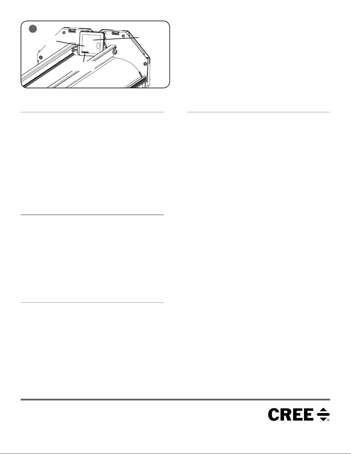
RESET RF MODULE
NOTE: The Blue LED is located behind the CREE logo on the RF
Module. The CREE logo with illuminate blue when the Blue LED is
active.
STEP 1:
Actuate RESET button through the access hole. Push and hold
until LED on RF Module begins blinking rapidly (approximately 6-7
seconds). See Figure 12.
STEP 2:
Release for 1 sec.
STEP 3:
Press/Hold RESET button for 0.5 sec. Light will turn off for a few
seconds then go to full bright and the Blue LED on the RF Module
should begin a 2 blink sequence. See Figure 12.
LED LUMINAIRE MAINTENANCE
Cleaning Instructions:
Regular cleaning of the light LED fixture is required to keep the LED
fixture operating at optical performance. Prior to cleaning fixtures,
turn power OFF to the fixture. Dust fixture regularly with a hand held
vacuum with a clean, non-lead, soft bristle brush to remove any dust
accumulation on the LED source on the LED and reflector surfaces.
Cleaning intervals to be no more than twelve months for clean
category environments and more frequently for dirtier conditions.
Care should be taken as to not damage the LED stick and/or the
interior reflective surface as these components are critical for optimal
performance. DO NOT use any type of cleaners or stiff brushes on the
LED fixture.
TROUBLESHOOTING:
Out of the box, if the light does not turn on when power is applied:
• Check Wiring with power off
• If wired correctly, check to see if Blue LED blinking on the
RF Module.
• If Blue LED is blinking, then perform a RESET (See RESET
RF MODULE section).
• If Blue LED is on solid or off, call Cree Customer Service.
• If you have done a RESET, and the light is still off, call Cree
Customer Service.
If light is unresponsive, use Cree Configuration Tool to verify
configuration.
FCC NOTICE
To comply with the FCC RF exposure compliance requirements,
this device and its antenna must not be co-located or operating to
conjunction with any other antenna or transmitter.
This equipment should be installed and operated with minimum
distance 5cm between the radiator & your body.
FCC COMPLIANCE STATEMENT
CAUTION: Changes or modifications not expressly approved could void
your authority to use this equipment.
This device complies with Part 15 of the FCC Rules. Operation to
the following two conditions: (1) This device may not cause harmful
interference, and (2) this device must accept any interference received,
including interference that may cause undesired operation
This device has been tested and found to comply with the limits
for a Class A digital device, pursuant to Part 15 of the FCC Rules.
These limits are designed to provide reasonable protection against
harmful interference when the device is operated in a commercial
environment. This device generates, uses, and can radiate radio
frequency energy and, if not installed and used in accordance with
the instruction manual, may cause harmful interference to radio
communications. Operation of this device in a residential area is likely
to cause harmful interference in which case the user will be required
to correct the interference at his own expense.
The LED in the front of this device operates within Risk Group 1 levels
per IEC 62471.
INDUSTRY CANADA STATEMENT
This device complies with Industry Canada licence-exempt RSS
standard(s). Operation is subject to the following two conditions: (1)
this device may not cause interference, and (2) this device must accept
any interference, including interference that may cause undesired
operation of the device. In addition, this device complies with ICES-003
of the Industry Canada (IC) Regulations.
Le présent appareil est conforme aux CNR d’Industrie Canada
applicables aux appareils radio exempts de licence. L’exploitation est
autorisée aux deux conditions suivantes : (1) l’appareil ne doit pas
produire de brouillage, et (2) l’utilisateur de l’appareil doit accepter
tout brouillage radioélectrique subi, même si le brouillage est
susceptible d’en compromettre le fonctionnement.
12
RF
Module
Access Hole, Reset
Button Inside
Blue LED Place-
ment

This manual suits for next models

1

Other Cree Lantern manuals

Cree 228 Series User manual

Cree

Cree 228 Series User manual

Cree DPT Series User manual

Cree

Cree DPT Series User manual

Cree RUL Series User manual

Cree

Cree RUL Series User manual

Cree THE EDGE Series User manual

Cree

Cree THE EDGE Series User manual

Cree CPY250 User manual

Cree

Cree CPY250 User manual

Cree C-Lite C-TR-A-FP User manual

Cree

Cree C-Lite C-TR-A-FP User manual

Cree IG Series User manual

Cree

Cree IG Series User manual

Cree FLEX Series User manual

Cree

Cree FLEX Series User manual

Cree Essentia FP Series User manual

Cree

Cree Essentia FP Series User manual

Cree KBL Series Installation instructions

Cree

Cree KBL Series Installation instructions

Cree WS Series User manual

Cree

Cree WS Series User manual

Cree Edge User manual

Cree

Cree Edge User manual

Cree 228 Series User manual

Cree

Cree 228 Series User manual

Cree XRAAF Series User manual

Cree

Cree XRAAF Series User manual

Cree XAK Series User manual

Cree

Cree XAK Series User manual

Cree Edge XAKE Series User manual

Cree

Cree Edge XAKE Series User manual

Cree CPY Series User manual

Cree

Cree CPY Series User manual

Cree ZR Series User manual

Cree

Cree ZR Series User manual

Cree LS8 User manual

Cree

Cree LS8 User manual

Cree XSP Series User manual

Cree

Cree XSP Series User manual

Cree CR Series User manual

Cree

Cree CR Series User manual

Cree RUL Series User manual

Cree

Cree RUL Series User manual

Popular Lantern manuals by other brands

GE High Mast Luminaire instructions

GE

GE High Mast Luminaire instructions

olympia electronics POWER LIGHT Series quick start guide

olympia electronics

olympia electronics POWER LIGHT Series quick start guide

Heitronic 36946 Installation and operating instructions

Heitronic

Heitronic 36946 Installation and operating instructions

WE-EF PFL230 Installation and maintenance instructions

WE-EF

WE-EF PFL230 Installation and maintenance instructions

Gama Sonic SOLAR COACH LANTERN manual

Gama Sonic

Gama Sonic SOLAR COACH LANTERN manual

IKEA STRALA J1834 manual

IKEA

IKEA STRALA J1834 manual

Singercon WIE-LED-80L user manual

Singercon

Singercon WIE-LED-80L user manual

Cooper safety STYLE Variant 58011 CGLine Fitting and operating instructions

Cooper safety

Cooper safety STYLE Variant 58011 CGLine Fitting and operating instructions

SIGNIFY Lumec Serenade DSX quick start guide

SIGNIFY

SIGNIFY Lumec Serenade DSX quick start guide

McLED Cala Series user manual

McLED

McLED Cala Series user manual

Allen + Roth WSL11BNK manual

Allen + Roth

Allen + Roth WSL11BNK manual

Venture Lighting SELECT-PRO Series user manual

Venture Lighting

Venture Lighting SELECT-PRO Series user manual

Siteco Monsun 41 manual

Siteco

Siteco Monsun 41 manual

Coleman 2000000870 How to use and enjoy

Coleman

Coleman 2000000870 How to use and enjoy

Trilux Belviso S CDP LED Series Mounting and operating instructions

Trilux

Trilux Belviso S CDP LED Series Mounting and operating instructions

Home Decorators Collection HBWI9002S86A Use and care guide

Home Decorators Collection

Home Decorators Collection HBWI9002S86A Use and care guide

Earth BRICK E.BR.01 Quick user guide

Earth

Earth BRICK E.BR.01 Quick user guide

SNOWJOE SUNJOE 24V-LGT500-CT Operator's manual

SNOWJOE

SNOWJOE SUNJOE 24V-LGT500-CT Operator's manual

manuals.online logo
manuals.online logoBrands
  • About & Mission
  • Contact us
  • Privacy Policy
  • Terms and Conditions

Copyright 2025 Manuals.Online. All Rights Reserved.