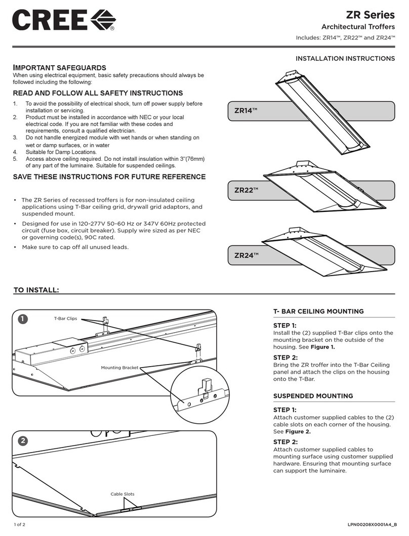
manuals.online logo
Brands
  1. Home
  2. •
  3. Brands
  4. •
  5. Cree
  6. •
  7. Lantern
  8. •
  9. Cree WS Series User manual

Cree WS Series User manual

WS Series
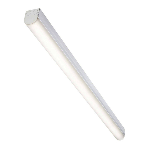
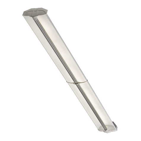
LED Linear Luminaire
Suspended Mount
INSTALLATION INSTRUCTIONS
1 of 3 LPN00501X0002A1_A
TO INSTALL:
SUSPENDED MOUNT
STEP 1:
Attach the bails to the mounting brackets
by gently pulling outward on the bail and
snapping it into the holes on the top of the
mounting bracket. See Figure 1 and 2.
STEP 2:
Attach air craft cables to the bracket
assembly. Attach the other end of the air
craft cable to ceiling. See Figure 2.
NOTE: It is recommended that the
dimensions between brackets equal about
70-80% of the luminaire’s length. The
luminaire will engage to the mounting
brackets at any point along it’s length,
except where there are latches.
Conduit Hole
Mounting Brackets
LED Tray
Lens Cover
Bail
Air Craft Cable
1
2
Bail
Air Craft Cable
Mounting Bracket
NOTES:
• For use with Cree Cable Suspension Kit.
• Liquid tight conduit fitting must be IP65 rated, supplied by
customer, to be used when attaching conduit to housing.
IMPORTANT SAFEGUARDS
When using electrical equipment, basic safety precautions should always
be followed including the following:
READ AND FOLLOW ALL SAFETY
INSTRUCTIONS
1. DANGER- Risk of shock- Disconnect power before installation.
DANGER – Risque de choc – Couper l’alimentation avant l’installation.
2. This luminaire must be installed in accordance with the NEC or your
local electrical code. If you are not familiar with these codes and
requirements, consult a qualied electrician.
Ce produit doit être installé conformément à NEC ou votre code
électrique local. Si vous n’êtes pas familier avec ces codes et ces
exigences, veuillez contacter un électricien qualié.
3. MIN. 75C SUPPLY CONDUCTORS.
LES FILS D’ALIMENTATION 75°C MIN.
4. SUITABLE FOR WET LOCATIONS.
CONVIENT AUX EMPLACEMENTS MOUILLES.
5. SUITABLE FOR OPERATION IN AMBIENT NOT EXCEEDING 40°C.
PEUT ETRE UTILISE A UNE TEMPERATURE AMBIANTE
N’EXCEDANT PAS 40°C.
6. SUITABLE FOR CONTINUOUS ROW MOUNTING.
PEUT ÊTRE MONTÉ EN RANGÉE CONTINUE.
SAVE THESE INSTRUCTIONS FOR
FUTURE REFERENCE
2 of 3 LPN00501X0002A1_A
STEP 3:
Insert one side of the luminaire
housing into the mounting brackets
as shown in Figure 3.
STEP 4:
Push up on the luminaire and then
press in on the mounting bracket
until the mounting bracket snaps into
place. See Figure 4.
STEP 5:
Remove lens cover by unhinging
the latches and set cover aside to
reinstall later.
STEP 6:
Let the LED Tray hang down from
bracket. See Figure 5.
STEP 7:
Insert customer supplied liquid tight
conduit and liquid tight conduit fitting
into desired conduit hole located on
the end of the housing. The dimension
of the conduit hole on the housing is
3/4” IP. Bring in customer supplied
cord and make wiring connections per
“Electrical Connection” section. See
Figure 1.
NOTE: Insert supplied plug into
unused conduit hole.
STEP 8:
Bring LED Tray back into housing and
secure by snapping in place using tray
brackets. See Figure 6.
STEP 9:
Reattach lens cover removed in Step 5
and secure using latches.
NOTE: If using tamper proof screws
(optional) insert screws into the (4)
latches located on the corners of the
housing before reattaching lens cover.
See Figure 7.
4
Mounting Bracket
Mounting Bracket
3
(4) Corner Latches
7
6Mounting Brackets
Tray Brackets
Tray
4
3 of 3 LPN00501X0002A1_A
lighting.cree.com
© 2018 Cree, Inc. All rights reserved. For informational purposes only. Content is subject to change.
See http://lighting.cree.com/warranty for warranty and specifications. Cree® is a registered trademark, and the Cree logo is a
trademark of Cree, Inc.
ELECTRICAL CONNECTIONS
STEP 1:
Using Listed 90°C minimum rated wire connectors make the following
electrical connections to the lever nuts:
a. For 120/277V connect the black fixture lead to the voltage supply
or Hot 1 (for 208/240/480V wiring).
b. For 120/277V connect the white fixture lead to the neutral supply
or Hot 2 (for 208/240/480V wiring).
c. Connect the green or green/yellow ground lead to ground.
d. If dimming is used; connect the violet dimming positive lead to
the supply dimming positive lead. If dimming is not being used,
ensure to cap off the violet lead
e. If dimming is used; connect the grey dimming negative lead to
the supply dimming negative lead. If dimming is not being used,
ensure to cap off the grey lead.
LINE
OR HOT 1
GREEN
LINE-BLACK
GROUND-GREEN
NEUTRAL-WHITE
DIM (-) GREY
DIM (+) VIOLET
NEUTRAL
OR HOT 2
VIOLET
GREY
SUPPLY WIRING
(DIMMING OPTIONAL)
LUMINAIRE

Other Cree Lantern manuals

Cree XSP Series User manual

Cree

Cree XSP Series User manual

Cree KBL Series Installation instructions

Cree

Cree KBL Series Installation instructions

Cree IG Series User manual

Cree

Cree IG Series User manual

Cree XRAAF Series User manual

Cree

Cree XRAAF Series User manual

Cree THE EDGE Series User manual

Cree

Cree THE EDGE Series User manual

Cree CPY250 User manual

Cree

Cree CPY250 User manual

Cree 228 Series User manual

Cree

Cree 228 Series User manual

Cree LS8 User manual

Cree

Cree LS8 User manual

Cree 228 Series User manual

Cree

Cree 228 Series User manual

Cree DPT Series User manual

Cree

Cree DPT Series User manual

Cree CPY Series User manual

Cree

Cree CPY Series User manual

Cree RUL Series User manual

Cree

Cree RUL Series User manual

Cree CS14 User manual

Cree

Cree CS14 User manual

Cree CR Series User manual

Cree

Cree CR Series User manual

Cree C-Lite C-TR-A-FP User manual

Cree

Cree C-Lite C-TR-A-FP User manual

Cree RUL Series User manual

Cree

Cree RUL Series User manual

Cree Edge User manual

Cree

Cree Edge User manual

Cree ZR Series User manual

Cree

Cree ZR Series User manual

Cree FLEX Series User manual

Cree

Cree FLEX Series User manual

Cree XAK Series User manual

Cree

Cree XAK Series User manual

Cree Essentia FP Series User manual

Cree

Cree Essentia FP Series User manual

Cree Edge XAKE Series User manual

Cree

Cree Edge XAKE Series User manual

Popular Lantern manuals by other brands

Philips HADCO IS_BL9 installation instructions

Philips

Philips HADCO IS_BL9 installation instructions

Kanlux HB PRO LED 100W-NW manual

Kanlux

Kanlux HB PRO LED 100W-NW manual

WHITECROFT LIGHTING ACL INDUSTRY Installation leaflet

WHITECROFT LIGHTING

WHITECROFT LIGHTING ACL INDUSTRY Installation leaflet

GE Lumination LRC Series installation guide

GE

GE Lumination LRC Series installation guide

Kichler Lighting LYNDON manual

Kichler Lighting

Kichler Lighting LYNDON manual

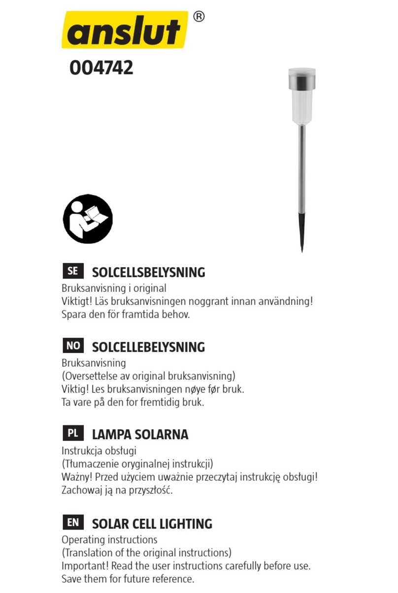
Anslut 004742 operating instructions

Anslut

Anslut 004742 operating instructions

DAVIS PANTHERA PTG Series Installation instruction

DAVIS

DAVIS PANTHERA PTG Series Installation instruction

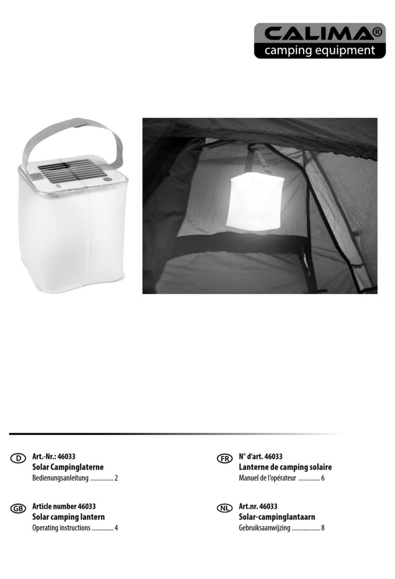
CALIMA 46033 operating instructions

CALIMA

CALIMA 46033 operating instructions

Soltech Cegonia user manual

Soltech

Soltech Cegonia user manual

Endon Burford Bollard instruction manual

Endon

Endon Burford Bollard instruction manual

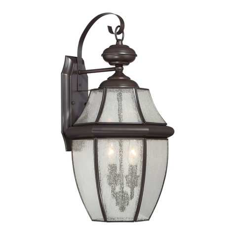
Quoizel NY8411K Assembly instruction sheet

Quoizel

Quoizel NY8411K Assembly instruction sheet

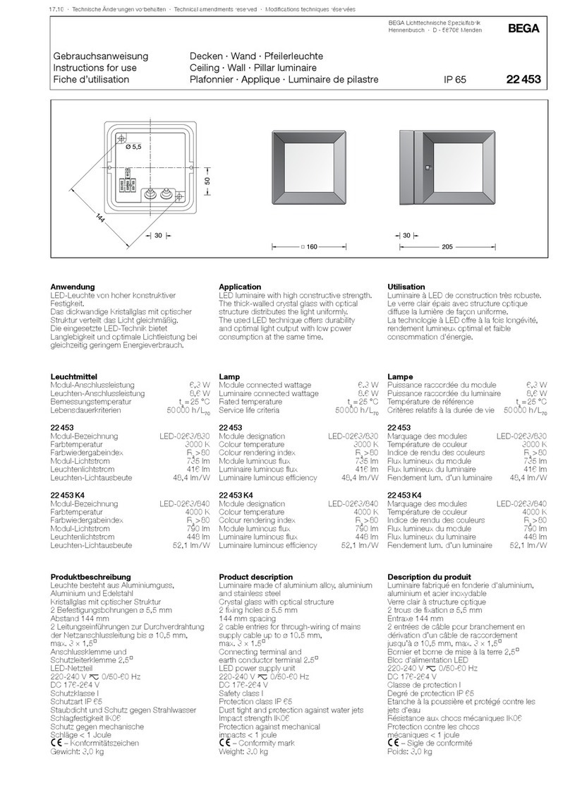
BEGA 22 453 Instructions for use

BEGA

BEGA 22 453 Instructions for use

RUSTA SCULLS manual

RUSTA

RUSTA SCULLS manual

WE-EF ETC330-GB LED Installation and maintenance instructions

WE-EF

WE-EF ETC330-GB LED Installation and maintenance instructions

BEGA 22 272 Instructions for use

BEGA

BEGA 22 272 Instructions for use

Nature Power 24801 instruction manual

Nature Power

Nature Power 24801 instruction manual

Bem EXO-900 user guide

Bem

Bem EXO-900 user guide

Targetti NANO PYROS 1E2827 manual

Targetti

Targetti NANO PYROS 1E2827 manual

manuals.online logo
manuals.online logoBrands
  • About & Mission
  • Contact us
  • Privacy Policy
  • Terms and Conditions

Copyright 2025 Manuals.Online. All Rights Reserved.