XLAMP®MH FAMILY LED SOLDERING & HANDLING
© 2014-2021 Cree LED. The information in this document is subject to change without notice. Cree®and the Cree logo are registered trademarks, and
the Cree LED logo is a trademark, of Cree, Inc. XLamp®is a registered trademark of Cree LED. Other trademarks, product and company names are
the property of their respective owners and do not imply specic product and/or vendor endorsement, sponsorship or association. This document is
provided for informational purposes only and is not a warranty or a specication. For product specications, please see the data sheets available at
www.cree-led.com.
CLD-AP193
REV 4 5
55
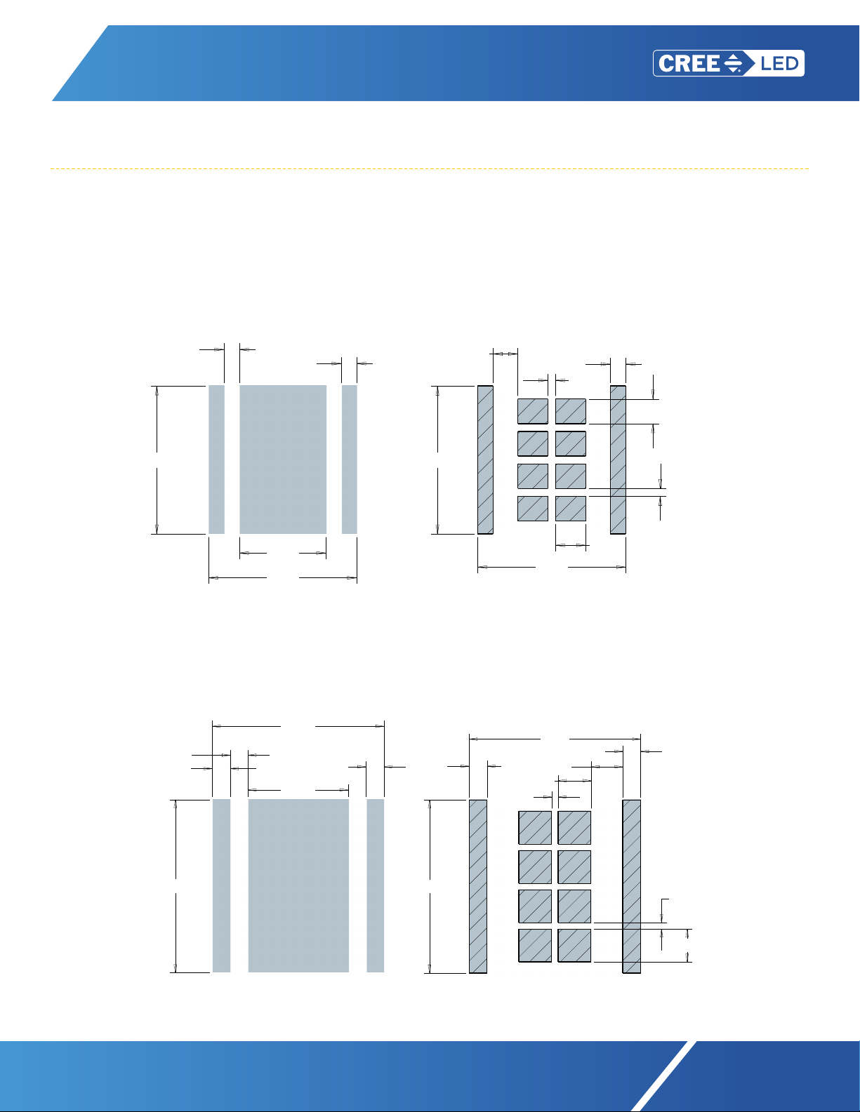
CIRCUIT BOARD PREPARATION & LAYOUTS
Printed circuit boards (PCBs) should be prepared and/or cleaned according to the manufacturer’s specications before placing or
soldering XLamp MH Family LEDs onto the PCB. The diagrams below show the recommended PCB solder pad layouts for XLamp MH
Family LEDs. The diagrams are not to scale.
All dimensions in mm
Tolerance: +0.13 mm
MHB-A 9-V, 18-V & 36-V Class
MHB-B 9-V, 18-V & 36-V Class
MHD-E 9-V/18-V Class - 9-V Conguration
MHD-E 36-V Class
MHD-G 18-V/36-V Class - 18-V Conguration
Recommended Stencil Pattern
(Shaded Area is Open)
Recommended PCB Solder Pad
SIZE
TITLE
OF
REV.
SHEET
C
DRAWING NO.
DATE
DATE
DATE
CHECK
FINAL PROTECTIVE FINISH
MATERIAL
APPROVED
DRAWN BY
THIRD ANGLE PROJECTION
SCALE
A
B
C
D
123456
6 5 4 3 2 1
A
B
C
D
Phone (919) 313-5300
Fax (919) 313-5558
4600 Silicon Drive
Durham, N.C 27703
UNAUTHORIZED PERSON WITHOUT
THE WRITTEN CONSENT
MAY NOT BE COPIED, REPRODUCED OR DISCLOSED TO ANY
CONFIDENTIAL INFORMATION OF CREE, INC. THIS PLOT
CONTAINED WITHIN ARE THE PROPRIETARY AND
CREE CONFIDENTIAL. THIS PLOT AND THE INFORMATION
OF CREE INC.
NOTICE
X° ± .5 °
.XXX ± .25
.XX ± .75
.X ± 1.5
FOR SHEET METAL PARTS ONLY
.XX ± .25
.XXX ± .125
X° ± .5 °
UNLESS OTHERWISE SPECIFIED
DIMENSIONS ARE IN
MILLIMETERS AND AFTER FINISH.
TOLERANCE UNLESS SPECIFIED:
SURFACE FINISH:
1.6
5.00
5.00
R2.26
3.02
0.73
.50
3.78
2.78
4.78
4.78
.50
4.78
.80
.50
.25
.80
.25
.97
4.78
.50
.50
2.78
4.78
4.78
1/116.000
B
2610-00032
OUTLINE DRAWING, 5050 XMLB
--
--
----
----
11/14/12D. CRONIN
REVISONS
REV DESCRIPTION BY DATE APP'D
RECOMMENDED PCB SOLDER PAD
RECOMMENDED STENCIL PATTERN
(HATCHED AREA IS OPENING)
ALL DIMENSIONS ARE ± .13MM UNLESS OTHERWISE NOTED
Recommended Stencil Pattern
(Shaded Area Is Open)
SIZE
TITLE
OF
REV.
SHEET
C
DRAWING NO.
DATE
DATE
DATE
CHECK
FINAL PROTECTIVE FINISH
MATERIAL
APPROVED
DRAWN BY
THIRD ANGLE PROJECTION
SCALE
A
B
C
D
123456
6 5 4 3 2 1
A
B
C
D
Phone (919) 313-5300
Fax (919) 313-5558
4600 Silicon Drive
Durham, N.C 27703
UNAUTHORIZED PERSON WITHOUT
THE WRITTEN CONSENT
MAY NOT BE COPIED, REPRODUCED OR DISCLOSED TO ANY
CONFIDENTIAL INFORMATION OF CREE, INC. THIS PLOT
CONTAINED WITHIN ARE THE PROPRIETARY AND
CREE CONFIDENTIAL. THIS PLOT AND THE INFORMATION
OF CREE INC.
NOTICE
X° ± .5 °
.XXX ± .25
.XX ± .75
.X ± 1.5
FOR SHEET METAL PARTS ONLY
.XX ± .25
.XXX ± .125
X° ± .5 °
UNLESS OTHERWISE SPECIFIED
DIMENSIONS ARE IN
MILLIMETERS AND AFTER FINISH.
TOLERANCE UNLESS SPECIFIED:
SURFACE FINISH:
1.6
7.00
7.00
0.75
±0.2 mm
.71
6.70
REF.
.35
±0.2 mm
6.70
REF.
6.70
.70
.50
6.70
4.30
2.95
.80
6.76
.70
.70
3.90
.70
6.70
6.76
6.70
1.24
1.29
.25
.70
.70
.25
1.29
1/115.000
B
2610-00051-OUTLINE
7x7 MHD-E 9V/36V
7x7 MHD-G 18V
11/12/14D. CRONIN
REVISONS
REV DESCRIPTION BY DATE APP'D
RECOMMENDED PCB SOLDER PAD
RECOMMENDED STENCIL PATTERN
(HATCHED AREA IS OPEN)
PRIMARY ALTERNATIVE
ALL DIMENSIONS ARE ± .13mm UNLESS OTHERWISE NOTED
Recommended PCB Solder Pad
SIZE
TITLE
OF
REV.
SHEET
C
DRAWING NO.
DATE
DATE
DATE
CHECK
FINAL PROTECTIVE FINISH
MATERIAL
APPROVED
DRAWN BY
THIRD ANGLE PROJECTION
SCALE
A
B
C
D
123456
6 5 4 3 2 1
A
B
C
D
Phone (919) 313-5300
Fax (919) 313-5558
4600 Silicon Drive
Durham, N.C 27703
UNAUTHORIZED PERSON WITHOUT
THE WRITTEN CONSENT
MAY NOT BE COPIED, REPRODUCED OR DISCLOSED TO ANY
CONFIDENTIAL INFORMATION OF CREE, INC. THIS PLOT
CONTAINED WITHIN ARE THE PROPRIETARY AND
CREE CONFIDENTIAL. THIS PLOT AND THE INFORMATION
OF CREE INC.
NOTICE
X° ± .5 °
.XXX ± .25
.XX ± .75
.X ± 1.5
FOR SHEET METAL PARTS ONLY
.XX ± .25
.XXX ± .125
X° ± .5 °
UNLESS OTHERWISE SPECIFIED
DIMENSIONS ARE IN
MILLIMETERS AND AFTER FINISH.
TOLERANCE UNLESS SPECIFIED:
SURFACE FINISH:
1.6
7.00
7.00
0.75
±0.2 mm
.71
6.70
REF.
.35
±0.2 mm
6.70
REF.
6.70
.70
.50
6.70
4.30
2.95
.80
6.76
.70
.70
3.90
.70
6.70
6.76
6.70
1.24
1.29
.25
.70
.70
.25
1.29
1/115.000
B
2610-00051-OUTLINE
7x7 MHD-E 9V/36V
7x7 MHD-G 18V
11/12/14D. CRONIN
REVISONS
REV DESCRIPTION BY DATE APP'D
RECOMMENDED PCB SOLDER PAD
RECOMMENDED STENCIL PATTERN
(HATCHED AREA IS OPEN)
PRIMARY ALTERNATIVE
ALL DIMENSIONS ARE ± .13mm UNLESS OTHERWISE NOTED