2 of 2 LPN00316X0001A3_A
www.lighting.cree.com
© 2018 Cree, Inc. All rights reserved. For informational purposes only. Content is subject to change.
See http://lighting.cree.com/warranty for warranty and specifications. Cree®is a registered trademark, and the Cree logo is a
trademark of Cree, Inc. NEMA®is a registered trademark of the National Electrical Manufacturers Association.
FIXTURE AIMING
STEP 1:
Remove the wiring compartment cover from the
adjustable fitter and set cover aside to reinstall
later. See Figure 1.
STEP 2:
Loosen 3/8" bolt in fitter wiring compartment.
STEP 3:
Adjust fixture to desired aiming angle, max 45
degree. The fixture may be aimed at 2-1/2°
increments. Markings are located on outside of fitter
for ease of aiming. See Figure 2.
STEP 4:
Tighten 3/8” bolt in fitter wiring compartment to
19 ft. lbs. (25 N•m).
STEP 5:
Replace the adjustable fitter wiring compartment
cover that was removed in Step 1 and secure with (3)
self retaining screws to 23 in. lbs (2.6 N•m). Make
sure not to pinch the O-ring or wires. See Figure 1.
NEMA®RECEPTACLE (OPTIONAL)
STEP 1:
Remove protective cap.
STEP 2:
Rotational adjustment of the photocontrol receptacle
is tool-less . DO NOT loosen/tighten the screws
securing the receptacle to the housing.
STEP 3:
Engage/install photocontrol into photocontrol
receptacle on to of luminaire.
STEP 4:
If necessary, rotate photo-control so its photo-eye is
aimed in the north direction. Some photo-controls
operate best somewhere between north-west and
north-east.
1/2" and 2" (51mm) Adjustable Fitter Positions
2
ELECTRICAL CONNECTIONS
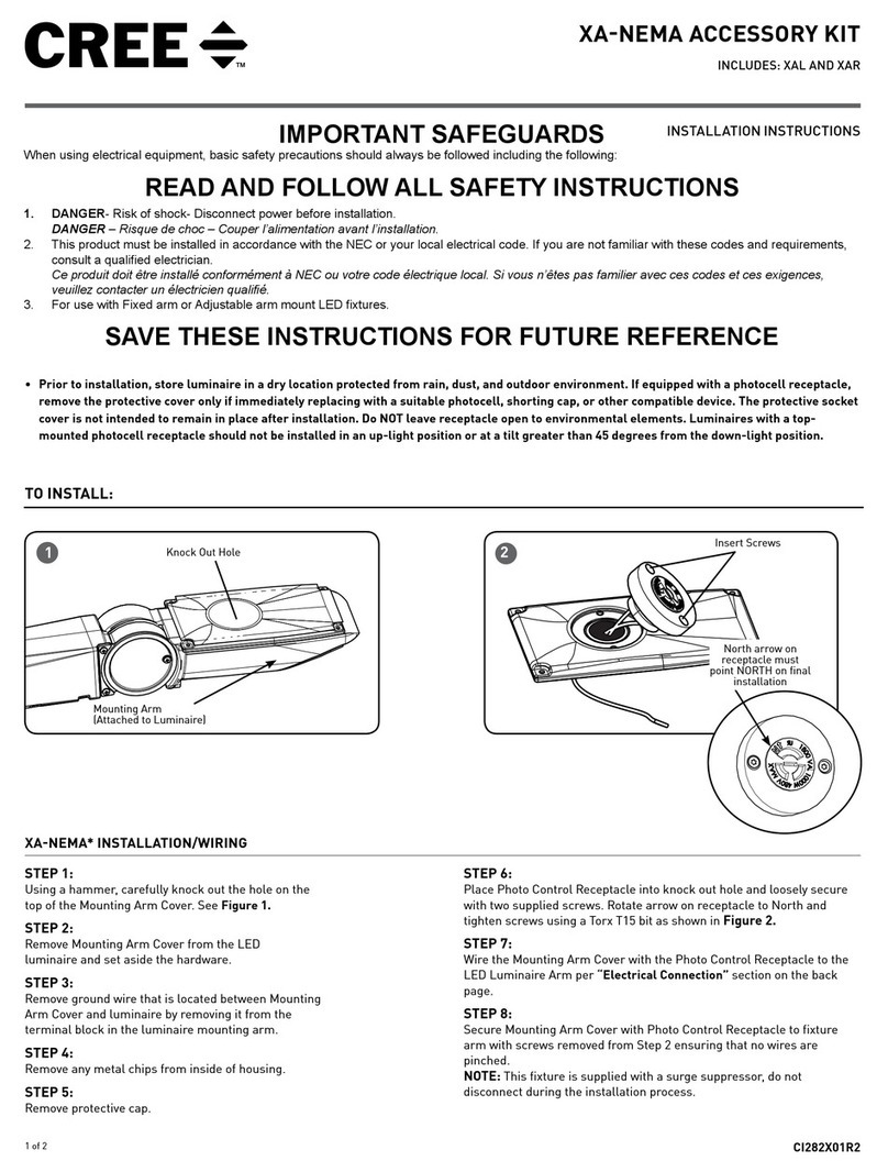
STEP 1:
Using Listed 90°C minimum rated wire connectors make the following
electrical connections within the pole:
a. For 120/277/347V connect the black fixture lead to the voltage
supply or Hot 1 (for 208/240/480V wiring).
b. For 120/277/347V connect the white fixture lead to the neutral
supply or Hot 2 (for 208/240/480V wiring).
c. Connect the green or green/yellow ground lead to ground.
d. If Dimming is an option; connect the violet dimming positive lead
to the supply dimming positive lead.
e. If Dimming is an option; connect the grey dimming negative lead
to the supply dimming negative lead.
LINE
OR HOT 1
GREEN
LINE-BLACK
GROUND-GREEN
NEUTRAL-WHITE
DIM (-) GREY
DIM (+) VIOLET
NEUTRAL
OR HOT 2
VIOLET
GREY
SUPPLY WIRING
(DIMMING OPTIONAL)
LUMINAIRE
Do Not Print After 10/24/18
