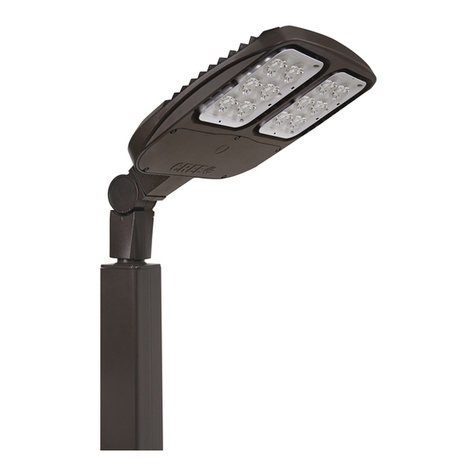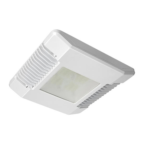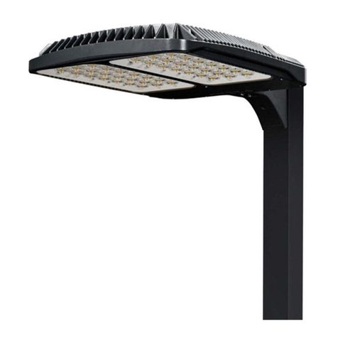
OSQ Series
LED Area Light
Adjustable Arm Mount
1 of 3 LPN00220X0001A4_A
INSTALLATION INSTRUCTIONS
INSTRUCTIONS D’INSTALLATION
IMPORTANT SAFEGUARDS
When using electrical equipment, basic safety precautions should always be followed including
the following:
READ AND FOLLOW ALL SAFETY INSTRUCTIONS
1. DANGER- Risk of shock- Disconnect power before installation.
DANGER – Risque de choc – Couper l’alimentation avant l’installation.
2. This luminaire must be installed in accordance with the NEC or your local electrical code.
If you are not familiar with these codes and requirements, consult a qualied electrician.
Ce produit doit être installé conformément à NEC ou votre code électrique local. Si vous
n’êtes pas familier avec ces codes et ces exigences, veuillez contacter un électricien
qualié.
SAVE THESE INSTRUCTIONS FOR FUTURE
REFERENCE
ADJUSTABLE ARM MOUNT INSTALLATION
NOTE: A 3/16" Allen screw driver is needed to
tighten the set screws.
NOTE: Access to Components Compartment
is not necessary for installation. To access the
Components Compartment, loosen (5) self-
retaining screws on the luminaire Cover Door.
See Figure 1.
STEP 1:
Remove the wiring compartment cover from the
adjustable fitter and set cover aside to reinstall
later. See Figure 1.
STEP 2:
Route the luminaire power supply cord into the
adjustable fitter wiring compartment.
STEP 3:
Engage the adjustable fitter onto the luminaire
using (4) 3/8"-16 set screws on the top of the
luminaire.
Torque set screws to 85 in-lbs (9.6 N•m).
STEP 4:
Cut leads 3" of length from the end of the
luminaire power supply cord and re-strip the
ends of the leads.
STEP 5:
Route the pole’s supply leads up through the
adjustable fitter and into the adjustable fitter
wiring compartment by puncturing the internal
seal with the supply leads. See
Figure 1.
STEP 6:
Strain relief is required for electrical
connections on the adjustable fitter mount for
mount heights of 25' (7.6 m) and higher. Tie a
knot in the supply wires above the hole in the
adjustable fitter wiring compartment to reduce
the strain on the connections. Make sure knot
will not slip through hole.
STEP 7:
Slip adjustable fitter over 2-3/8"
(60 mm) O.D. heavy wall pipe or tenon and
securely tighten two Allen head set screws with
3/16" Allen wrench to 18 ft. lbs. (24 N•m). See
Figure 1.
STEP 8:
Make wire connections in wiring compartment
of adjustable fitter per Electrical Connections
section on the back page.
STEP 9:
Replace the adjustable fitter compartment
cover that was removed in Step 1 and secure
with (3) self-retaining screws. Make sure not to
pinch the O-ring. See Figure 1.
TO INSTALL:
1Luminaire Cover
Door
Adjustable
Fitter Wiring
Compartment
O-Ring
Wiring
Compartment Cover Allen Head Set
Screws
Adjustable Fitter
(4) Set Screws
Fitter O-Ring
(Factory Installed)
DO NOT remove knockout
• Prior to installation, store luminaire in a dry location protected from rain, dust, and outdoor
environment. If equipped with a photocell receptacle, remove the protective cover only if
immediately replacing with a suitable photocell, shorting cap, or other compatible device.
The protective socket cover is not intended to remain in place after installation. Do NOT
leave receptacle open to environmental elements. Luminaires with a top-mounted photocell
receptacle should not be installed in an up-light position or at a tilt greater than 45 degrees
from the down-light position.
NOTE:
• DO NOT remove the knock out on the top of the
luminaire (See Figure 1 below). If a NEMA or
photocontrol is desired customer must order
OSQ luminaire with factory installed NEMA
Photocell Receptacle (R option).
NEMA photocell receptacle or photo control’s
are not field installable.
