manuals.online logo
Brands
  1. Home
  2. •
  3. Brands
  4. •
  5. Crestron
  6. •
  7. Switch
  8. •
  9. Crestron DM Lite HD-RX-4K-510-C-E User manual

Crestron DM Lite HD-RX-4K-510-C-E User manual

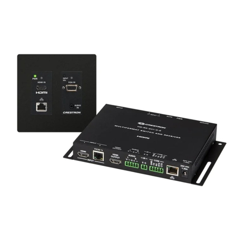
The Crestron® HD-RX-4K-510-C-E is a DM Lite™ 4K multiformat switch and receiver that
provides enhanced HDMI® video switching and audio presentation capabilities in areas such as
conference rooms and classrooms. The HD-RX-4K-510-C-E can be connected to up to three
DM Lite transmitters.
Check the Box
Item Qty
HD-RX-4K-510-C-E 1
Anchor, Drywall, Plastic (P/N 2053825) 4
Connector, 2-Pin (P/N 2003574) 5
Connector, 2-Pin (P/N 2044402) 2
Connector, 3-Pin (P/N 2003575) 3
Connector, 5-Pin (P/N 2003577) 5
Power Cord, 6 ft 7 in. (2 m) (P/N 2001134) 1
Screw, 8-15A x 3/4 in., Flat Head, Phillips (P/N 2053836) 4
Install the Device
To install the device, mount it onto drywall. Use the four included drywall anchors and the four
included 8-15A x 3/4 in. at head Phillips screws (one screw for each keyhole slot in the four
mounting anges of the device).
NOTE: For safety reasons, it is recommended that the mounting height of the device be no more
than 6-1/2 ft (2 m) from the oor or any platform above which the device is mounted.
Drywall Mounting
(4) Screws, 8-15A x 3/4 in.
(included)
Drywall
HD-RX-4K-510-C-E
(4) Mounting flange
keyhole slots
(2 each side)
(4) Anchors
(included)
Connect the Device
Connect the device as required for the application.
Front Panel Connection
SERVICE:
For firmware
and EDID
loading
PWR
LED
INPUT Selection
1-5
LEDs and
push buttons
AUTO
LED and
push button
SETUP
LED and
push button
Rear Panel Connections
DM LITE
INPUTS 5, 4, 3:
From
DM Lite™
transmitters
HDMI
INPUTS 2, 1:
From HDMI®
audio/video
sources
HDMI
OUTPUT:
To HDMI
display
:
100BASE-TX/
1000BASE-T
Ethernet to
local area network
IR:
To IR
controllable
device
COM:
To RS-232
device
SPEAKER L/R OUT:
To 4-ohm or
8-ohm
stereo speakers
100-240V~2.0A
50/60 Hz:
From AC
power outlet
I/O 1-2:
To I/O
controllable
devices
RLY 1-2:
To contact
closure
devices
LINE L/R 1-2 :
From balanced/
unbalanced stereo line
level audio sources
MIC 1-2:
From balanced
microphone
audio sources
AUX:
From balanced
auxiliary
audio source
AUX OUT 1-2:
To balanced/
unbalanced
auxiliary
audio devices
NOTES:
• Cabling that connects the HD-RX-4K-510-C-E to a DM Lite transmitter is designed for
intrabuilding use only.
• The HD-RX-4K-510-C-E can power three DM Lite transmitters simultaneously. Do not
connect power to transmitters that are to be connected to the HD-RX-4K-510-C-E.
• The HD-RX-4K-510-C-E is grounded by connection of the included power cord to an
AC power outlet with proper grounding.
• There are no user-serviceable parts inside this device. If repair of the device is needed,
contact an authorized Crestron dealer for return of the device to the factory.
LINE 1-2 Connector Pin Assignments
The LINE 1 and LINE 2 connectors use 5-pin terminal blocks for balanced or unbalanced analog
audio inputs.
LINE 1-2 Connector
+ +
–
–
Refer to the following table and diagrams for analog audio input pin assignments and
connection information.
Signal Name Balanced Audio Input Unbalanced Audio Input
+ L+ L+ In
–L– L– signal return, jumper to GND
G Shield/ground Ground
+ R+ R+ In
–R– R– signal return, jumper to GND
Jumpers
+ -
G
+ -
+
+
L R
Source L
Source R
Shield
Shield
+ -
G
+ -
+
+
Shield
L R
Source L
Source R
Unbalanced Input
Balanced Input
AUX OUT 1-2 Connector Pin Assignments
The AUX OUT 1 and AUX OUT 2 connectors use 5-pin terminal blocks for balanced or unbalanced
analog audio outputs.
AUX OUT 1-2 Connector
+ +
–
–
Refer to the following table and diagrams for analog audio output pin assignments and
connection information.
Signal Name Balanced Audio Output Unbalanced Audio Output
+ L+ L+ Out
–L– Open
G Shield/ground Common ground
+ R+ R+ Out
–R– Open
AMP
Left
Right
+ - G+ -
Unbalanced Output
L R
+
+
Shield
AMP
Left
Right
+ - G+ -
Balanced Output
L R
+
+
HD-RX-4K-510-C-E
DM Lite™ 4K Multiformat Switch and Receiver
LED Indicators
Refer to the following table for information about the LED indicators on the device.
LED Indicator Color Meaning
PWR Amber Power is being applied to the device. The device is booting.
Green Power is being applied to the device. The device is
operational.
INPUT 1-5 Green The corresponding input is selected. Video is detected and
switched.
Amber The corresponding input is selected. Video is detected but
is not switched.
AUTO Green Automatic switching is enabled.
SETUP Red The SETUP button is pressed.
DM LITE Green
(right LED)
A DM Lite link is established.
Flashing amber Non-HDCP video is detected.
Steady amber HDCP video is detected.
LAN Green An Ethernet link is established.
Flashing amber Data activity is occurring on the Ethernet link.
Configure the Device
Using the web interface, congure the HD-RX-4K-510-C-E. The HD-RX-4K-510-C-E also hosts
the conguration of the connected transmitters.
To access the web interface, open a web browser and then go to the IP address of the
HD-RX-4K-510-C-E. By default, DHCP is enabled. To display the IP address on the connected
HDMI display, press the SETUP button on the front panel of the HD-RX-4K-510-C-E. If the
transmitter has a SETUP button, pressing the button on the transmitter will also display the IP
address of the HD-RX-4K-510-C-E.
To log in to the web interface, enter the user name and password. The default user name and
password are both admin.
Upgrade the Firmware
Before using the device, upgrade the rmware. The latest rmware can be downloaded from the
HD-RX-4K-510-C-E product page on the Crestron website (www.crestron.com).
Additional Information
Scan or click the QR code for detailed product information.
HD-RX-4K-510-C-E
Compliance and Legal
Original Instructions: The U.S. English version of this document is the original instructions. All other languages are a translation
of the original instructions.
Regulatory Model: M1845002
Federal Communications Commission (FCC) Compliance Statement
This device complies with part 15 of the FCC Rules. Operation is subject to the following conditions: (1) This device may not
cause harmful interference and (2) this device must accept any interference received, including interference that may cause
undesired operation.
CAUTION: Changes or modications not expressly approved by the manufacturer responsible for compliance could void the
user’s authority to operate the equipment.
NOTE: This equipment has been tested and found to comply with the limits for a Class B digital device, pursuant to part 15
of the FCC Rules. These limits are designed to provide reasonable protection against harmful interference in a residential
installation. This equipment generates, uses and can radiate radio frequency energy and, if not installed and used in
accordance with the instructions, may cause harmful interference to radio communications. However, there is no guarantee
that interference will not occur in a particular installation. If this equipment does cause harmful interference to radio or
television reception, which can be determined by turning the equipment o and on, the user is encouraged to try to correct the
interference by one or more of the following measures:
• Reorient or relocate the receiving antenna.
• Increase the separation between the equipment and receiver.
• Connect the equipment into an outlet on a circuit dierent from that to which the receiver is connected.
• Consult the dealer or an experienced radio/TV technician for help.
Industry Canada (IC) Compliance Statement
CAN ICES-3 (B)/NMB-3(B)
As of the date of manufacture, the product has been tested and found to comply with specications for CE marking.
This product is Listed to applicable UL® Standards and requirements tested by Underwriters Laboratories Inc.
Ce produit est homologué selon les normes et les exigences UL applicables par Underwriters Laboratories Inc.
The product warranty can be found at www.crestron.com/warranty.
The specic patents that cover Crestron products are listed at www.crestron.com/legal/patents.
Certain Crestron products contain open source software. For specic information, please visit www.crestron.com/opensource.
Crestron, the Crestron logo, and DM Lite are either trademarks or registered trademarks of Crestron Electronics, Inc. in the
United States and/or other countries. HDMI and the HDMI logo are either trademarks or registered trademarks of HDMI
Licensing in the United States and/or other countries. UL and the UL logo are either trademarks or registered trademarks of
Underwriters Laboratories, Inc. in the United States and/or other countries. Other trademarks, registered trademarks, and
trade names may be used in this document to refer to either the entities claiming the marks and names or their products.
Crestron disclaims any proprietary interest in the marks and names of others. Crestron is not responsible for errors in
typography or photography.
©2019 Crestron Electronics, Inc.
Crestron Electronics, Inc.
15 Volvo Drive, Rockleigh, NJ 07647
Tel: 888.CRESTRON
Fax: 201.767.7576
www.crestron.com
Quick Start - Doc. 8456B
(2053624)
06/27/19
Specications subject to
change without notice.
Other Crestron Switch manuals

Crestron CNXHUB User manual

Crestron

Crestron CNXHUB User manual

Crestron CLX-4HSW4 User manual

Crestron

Crestron CLX-4HSW4 User manual

Crestron DigitalMedia DM-MD64X64 User manual

Crestron

Crestron DigitalMedia DM-MD64X64 User manual

Crestron infiNET CLW-SLVS1RF User manual

Crestron

Crestron infiNET CLW-SLVS1RF User manual

Crestron CEN-SWPOE-16 User manual

Crestron

Crestron CEN-SWPOE-16 User manual

Crestron HD-MD-300-C-E User manual

Crestron

Crestron HD-MD-300-C-E User manual

Crestron CEN-SW-POE-5 User manual

Crestron

Crestron CEN-SW-POE-5 User manual

Crestron HD-TX-301-C-E Dimensional drawing

Crestron

Crestron HD-TX-301-C-E Dimensional drawing

Crestron CLCI-1SW2EX-W User manual

Crestron

Crestron CLCI-1SW2EX-W User manual

Crestron ZUM-FLOOR-HUB Dimensional drawing

Crestron

Crestron ZUM-FLOOR-HUB Dimensional drawing

Crestron Green Light GL-IPAC-SW8 User manual

Crestron

Crestron Green Light GL-IPAC-SW8 User manual

Crestron DM NVX Director DM-NVX-DIR Series User manual

Crestron

Crestron DM NVX Director DM-NVX-DIR Series User manual

Crestron DigitalMedia DM-MD6X1 User manual

Crestron

Crestron DigitalMedia DM-MD6X1 User manual

Crestron infiNET CLW-SLVS1RF User manual

Crestron

Crestron infiNET CLW-SLVS1RF User manual

Crestron DigitalMedia XiO Director DM-XIO-DIR-160 Dimensional drawing

Crestron

Crestron DigitalMedia XiO Director DM-XIO-DIR-160 Dimensional drawing

Crestron DM-MD8X1-4K-C Dimensional drawing

Crestron

Crestron DM-MD8X1-4K-C Dimensional drawing

Crestron DM NVX Series User manual

Crestron

Crestron DM NVX Series User manual

Crestron Network Device PWE-4803RU User manual

Crestron

Crestron Network Device PWE-4803RU User manual

Crestron DigitalMedia DM-MD64X64 User manual

Crestron

Crestron DigitalMedia DM-MD64X64 User manual

Crestron Sonnex SWE-8 User manual

Crestron

Crestron Sonnex SWE-8 User manual

Crestron HD-MD6X2-4K-E Owner's manual

Crestron

Crestron HD-MD6X2-4K-E Owner's manual

Crestron HD-SCALER-HD-E Dimensional drawing

Crestron

Crestron HD-SCALER-HD-E Dimensional drawing

Crestron 8x8 DigitalMedia DM-MD8X8 User manual

Crestron

Crestron 8x8 DigitalMedia DM-MD8X8 User manual

Crestron CEN-SWPOE-16 Dimensional drawing

Crestron

Crestron CEN-SWPOE-16 Dimensional drawing

Popular Switch manuals by other brands

ACS Thermocont TS4L Technical manual

ACS

ACS Thermocont TS4L Technical manual

TILLIG BAHN 85640 Assembly instructions

TILLIG BAHN

TILLIG BAHN 85640 Assembly instructions

Garland EdgeSafe M10GMSBPv2 user guide

Garland

Garland EdgeSafe M10GMSBPv2 user guide

PRO SIGNAL PSG3055 quick start guide

PRO SIGNAL

PRO SIGNAL PSG3055 quick start guide

Belkin OMNIVIEW P74696 user manual

Belkin

Belkin OMNIVIEW P74696 user manual

Lantech IPES-5222T Series user manual

Lantech

Lantech IPES-5222T Series user manual

VigilLink VLIP-JP4k3K user manual

VigilLink

VigilLink VLIP-JP4k3K user manual

Grizzly T25448 instructions

Grizzly

Grizzly T25448 instructions

Belden Hirschmann DRAGON MACH Series user manual

Belden

Belden Hirschmann DRAGON MACH Series user manual

steute Ex 95 Mounting and wiring instructions

steute

steute Ex 95 Mounting and wiring instructions

NETGEAR FS108 - ProSafe 10/100 Desktop Switch Product data

NETGEAR

NETGEAR FS108 - ProSafe 10/100 Desktop Switch Product data

Cisco MGX 8950 Product overview

Cisco

Cisco MGX 8950 Product overview

Multico EW-K1302DPC4K Quick installation guide

Multico

Multico EW-K1302DPC4K Quick installation guide

Icy Box IB-HUB1429-CPD user manual

Icy Box

Icy Box IB-HUB1429-CPD user manual

Symbol WS 2000 System reference

Symbol

Symbol WS 2000 System reference

CyberData 011508 Installation quick reference

CyberData

CyberData 011508 Installation quick reference

United Electric Controls Spectra 12 Series Installation and maintenance instructions

United Electric Controls

United Electric Controls Spectra 12 Series Installation and maintenance instructions

ZyXEL Communications ZyXEL Dimension ES-2724 Specifications

ZyXEL Communications

ZyXEL Communications ZyXEL Dimension ES-2724 Specifications

manuals.online logo
manuals.online logoBrands
  • About & Mission
  • Contact us
  • Privacy Policy
  • Terms and Conditions

Copyright 2025 Manuals.Online. All Rights Reserved.