manuals.online logo
Brands
  1. Home
  2. •
  3. Brands
  4. •
  5. Crestron
  6. •
  7. Switch
  8. •
  9. Crestron HD-TX-201-C-2G-E Dimensional drawing

Crestron HD-TX-201-C-2G-E Dimensional drawing

DO GUIDE
HD-TX-201-C-2G-E
DM Lite Multiformat Switch and Transmitter
2. Using a Phillips screwdriver (not included), attach the device to the electrical box using the
four included #6-32 x 3/4-inch truss combo head screws.
3. Attach a decorator-style faceplate (sold separately) to the front panel of the device using
four screws (not included).
DO Install the Device
Install the device into a 2-gang electrical box (not included). A minimum mounting depth of 2 inches
(51 mm) is required.
To install the device:
1. On the rear of the device, make connections to the TO RX and Ethernet ports.
NOTES:
• For the 24 Vdc power connection, connect a power pack to either the transmitter or
a compatible receiver. Do not connect a power pack to both devices simultaneously.
Power is transmitted over the cable that connects the TO RX port on the transmitter to
the FROM RX port on the receiver.
A power pack is not included with the transmitter. When the transmitter is used with a
DM Lite surface-mount receiver, the transmitter receives power from the power pack
that ships with and connects to the receiver.
• Cabling that connects the TO RX port to the FROM TX port is designed for
intrabuilding use only.
DO Check the Box
QTY ITEM PART NUM.
4 Screw, 6-32 x 3/4", Truss Head, Combo 2009211
TO RX:
To FROM TX
link input of
receiver
Passive
pass-through
to front panel
Ethernet port
:
24 V
1.25 A:
From power pack
(not included)
24 G
DO GUIDE DOC. 8333A (2052143) 06.18
Specications subject to change without notice.
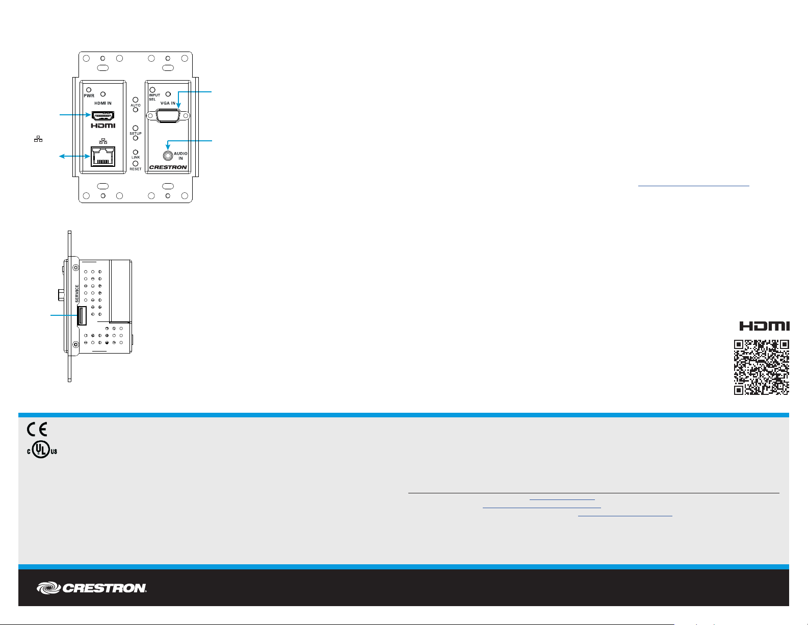
DO Connect the Device
Connect the device as required for the application.
The SERVICE port is for factory use only.
DO Congure the Device
To congure the device, do either of the following:
• If the transmitter connects to an HD-RX-201-C-E, the HD-RX-201-C-E hosts the
conguration of the transmitter. As a result, congure the transmitter using the web
interface of the HD-RX-201-C-E.
To access the web interface, open a web browser and then go to the IP address of the
HD-RX-201-C-E. By default, DHCP is enabled. To display the IP address on the
connected HDMI®display, press the SETUP button on the front panel of the
HD-RX-201-C-E. Pressing the SETUP button on the transmitter will also display the
IP address of the HD-RX-201-C-E.
To log in to the web interface, enter the user name and password. The default user name
and password are both admin.
• If the transmitter does not connect to an HD-RX-201-C-E, refer to Answer ID 1000168
in the Online Help section of the Crestron website (www.crestron.com/onlinehelp) for
conguration information.
NOTE: When the transmitter does not connect to the HD-RX-201-C-E, pressing the
SETUP button on the transmitter has no effect.
As of the date of manufacture, the product has been tested and found to comply with specications for CE marking.
This product is Listed to applicable UL®Standards and requirements tested by Underwriters Laboratories Inc.
Ce produit est homologué selon les normes et les exigences UL applicables par Underwriters Laboratories Inc.
Federal Communications Commission (FCC) Compliance Statement
This device complies with part 15 of the FCC Rules. Operation is subject to the following two conditions:
(1) This device may not cause harmful interference, and (2) this device must accept any interference received, including interference
that may cause undesired operation.
CAUTION:Changes or modications not expressly approved by the manufacturer responsible for compliance could void the user’s
authority to operate the equipment.
NOTE: This equipment has been tested and found to comply with the limits for a Class B digital device, pursuant to part 15 of the
FCC Rules. These limits are designed to provide reasonable protection against harmful interference in a residential installation.
This equipment generates, uses and can radiate radio frequency energy and, if not installed and used in accordance with the
instructions, may cause harmful interference to radio communications. However, there is no guarantee that interference will not
occur in a particular installation.
If this equipment does cause harmful interference to radio or television reception, which can be determined by turning the
equipment off and on, the user is encouraged to try to correct the interference by one or more of the following measures:
• Reorient or relocate the receiving antenna.
• Increase the separation between the equipment and receiver.
• Connect the equipment into an outlet on a circuit different from that to which the receiver is connected.
• Consult the dealer or an experienced radio/TV technician for help.
Industry Canada (IC) Compliance Statement
CAN ICES-3(B)/NMB-3(B)
The specic patents that cover Crestron products are listed at www.crestron.com/legal/patents.
The product warranty can be found at www.crestron.com/legal/sales-terms-conditions-warranties.
Certain Crestron products contain open source software. For specic information, visit www.crestron.com/legal/open-source-software.
Crestron and the Crestron logo are either trademarks or registered trademarks of Crestron Electronics, Inc., in the United States and/or other countries. HDMI and the HDMI logo are either
trademarks or registered trademarks of HDMI Licensing LLC in the United States and/or other countries. UL and the UL logo are either trademarks or registered trademarks of Underwriters
Laboratories, Inc. in the United States and/or other countries. Other trademarks, registered trademarks, and trade names may be used in this document to refer to either the entities claiming
the marks and names or their products. Crestron disclaims any proprietary interest in the marks and names of others. Crestron is not responsible for errors in typography or photography.
This document was written by the Technical Publications department at Crestron.
©2018 Crestron Electronics, Inc.
SERVICE:
For factory
use only
Passive
pass-through
to rear panel
Ethernet port
HDMI IN:
From HDMI®
audio/video
source
:
VGA IN:
From RGB (VGA)
or component
video output
AUDIO IN:
From unbalanced
stereo line level
audio output
DO Learn More
Visit the website for additional information and the latest rmware updates. To learn
more about this product, use a QR reader application on your mobile device to scan
the QR image.
Crestron Electronics
15 Volvo Drive, Rockleigh, NJ 07647
888.CRESTRON | www.crestron.com

Other Crestron Switch manuals

Crestron DigitalMedia DM-MD8X8-CPU3 User manual

Crestron

Crestron DigitalMedia DM-MD8X8-CPU3 User manual

Crestron 8x8 DigitalMedia DM-MD8X8 User manual

Crestron

Crestron 8x8 DigitalMedia DM-MD8X8 User manual

Crestron HD-MD6X2-4K-E Owner's manual

Crestron

Crestron HD-MD6X2-4K-E Owner's manual

Crestron DigitalMedia User manual

Crestron

Crestron DigitalMedia User manual

Crestron 8x8 DigitalMedia DM-MD8X8 User manual

Crestron

Crestron 8x8 DigitalMedia DM-MD8X8 User manual

Crestron C2N-MMS User manual

Crestron

Crestron C2N-MMS User manual

Crestron CNLGE-8 User manual

Crestron

Crestron CNLGE-8 User manual

Crestron ZUM-FLOOR-HUB Dimensional drawing

Crestron

Crestron ZUM-FLOOR-HUB Dimensional drawing

Crestron 8x8 DigitalMedia DM-MD8X8 User manual

Crestron

Crestron 8x8 DigitalMedia DM-MD8X8 User manual

Crestron CLW-LSWEX-1GD Operating instructions

Crestron

Crestron CLW-LSWEX-1GD Operating instructions

Crestron HDI-TX-301-C-2G-E Dimensional drawing

Crestron

Crestron HDI-TX-301-C-2G-E Dimensional drawing

Crestron CLX-4HSW4 User manual

Crestron

Crestron CLX-4HSW4 User manual

Crestron CNLGE-8 User manual

Crestron

Crestron CNLGE-8 User manual

Crestron CEN-SW-POE-5 User manual

Crestron

Crestron CEN-SW-POE-5 User manual

Crestron HD-RX-4K-210-C-E User manual

Crestron

Crestron HD-RX-4K-210-C-E User manual

Crestron infiNET CLW-SLVS1RF User manual

Crestron

Crestron infiNET CLW-SLVS1RF User manual

Crestron DigitalMedia XiO Director DM-XIO-DIR-160 Dimensional drawing

Crestron

Crestron DigitalMedia XiO Director DM-XIO-DIR-160 Dimensional drawing

Crestron Prodigy P-LSWEX User manual

Crestron

Crestron Prodigy P-LSWEX User manual

Crestron MPI-WP100 User manual

Crestron

Crestron MPI-WP100 User manual

Crestron infiNET CLW-SLVS1RF User manual

Crestron

Crestron infiNET CLW-SLVS1RF User manual

Crestron CNXHUB User manual

Crestron

Crestron CNXHUB User manual

Crestron ZUM-FLOOR-HUB User manual

Crestron

Crestron ZUM-FLOOR-HUB User manual

Crestron HD-TX-301-C-E Dimensional drawing

Crestron

Crestron HD-TX-301-C-E Dimensional drawing

Crestron Sonnex SWE-8 User manual

Crestron

Crestron Sonnex SWE-8 User manual

Popular Switch manuals by other brands

OT Systems IET8242MPpH-S-DR manual

OT Systems

OT Systems IET8242MPpH-S-DR manual

Vigatec MGVC 1280 Operation manual

Vigatec

Vigatec MGVC 1280 Operation manual

NETGEAR FS108P - ProSafe Switch Brochure & specs

NETGEAR

NETGEAR FS108P - ProSafe Switch Brochure & specs

steute KF Mounting and wiring instructions

steute

steute KF Mounting and wiring instructions

Ocean Optics FOS-2x2-TTL Installation and operation manual

Ocean Optics

Ocean Optics FOS-2x2-TTL Installation and operation manual

Avocent 120 Quick installation guide

Avocent

Avocent 120 Quick installation guide

Honeywell MICRO SWITCH GSX installation instructions

Honeywell

Honeywell MICRO SWITCH GSX installation instructions

Dell S4820T Configuration guide

Dell

Dell S4820T Configuration guide

LEGRAND DMX installation manual

LEGRAND

LEGRAND DMX installation manual

Hitachi MS-1 quick guide

Hitachi

Hitachi MS-1 quick guide

StarTech.com SV1107IPEXT instruction manual

StarTech.com

StarTech.com SV1107IPEXT instruction manual

Konig CMP-KVMSWIT20 manual 

Konig

Konig CMP-KVMSWIT20 manual 

Nortel 5510 Configuration

Nortel

Nortel 5510 Configuration

Arista 7000 Series quick start guide

Arista

Arista 7000 Series quick start guide

Roland FS-1-WL Connection guide

Roland

Roland FS-1-WL Connection guide

Chima STE-2226-GW user manual

Chima

Chima STE-2226-GW user manual

TRENDnet TEG-2224WS Specifications

TRENDnet

TRENDnet TEG-2224WS Specifications

axing basic-line Series Operation instructions

axing

axing basic-line Series Operation instructions

manuals.online logo
manuals.online logoBrands
  • About & Mission
  • Contact us
  • Privacy Policy
  • Terms and Conditions

Copyright 2025 Manuals.Online. All Rights Reserved.