manuals.online logo
Brands
  1. Home
  2. •
  3. Brands
  4. •
  5. Crow
  6. •
  7. Security Sensor
  8. •
  9. Crow TLC-360 User manual

Crow TLC-360 User manual

1 2 3
TLC-360
4ELEMENT
CEILINGMOUNT
PASSIVE INFRAREDDETECTOR
INSTALLATIONINSTRUCTIONS
P/N7151069 REV.EA.Y.
TLC-360 FEATURES
∗Fullysealedsensorchamber.
∗VLSI Technology(VeryLargeScale
Integration).
∗MaximumRFI &EMI Immunity.
∗4Element PyroSensor.
∗PulseCount.
∗Sophisticatedsignalprocessing.
∗Memoryfunction.
∗HardSphericalLens360°coverage.
∗Bidirectionaltemperaturecompensation.
∗Flourescent light stability.
INTRODUCTION
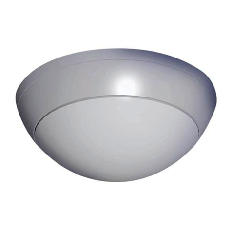
TheTLC-360 isa4-element passiveinfrared
intrusiondetectorforusein electronic
securitysystemsin ceiling mount
applications.
Youwill obtain optimumperformancefrom
yourTLC-360 PIRdetectorbyfollowing this
manual.
TheTLC-360 reducesfalsealarmstoan
unprecedentedminimallevelduetoits
effectiveeliminationofbackground noisesand
nuisancestimuli. TheTLC-360 employs
AutomaticPulseCount making it extremely
adaptabletovariousenvironments. The
uniqueVLSI, using sophisticatedsignal
processing, makesthisdetectorvirtuallyfree
offalsealarms.
TheTLC-360 integratesVLSI &SMD
(surfacemount device)totheirfull advantage.
Thedetectoriseasytoinstall, withno
necessaryadjustments.
HARDSPHERICAL LENS
TheTLC-360 isequippedwithaspecialhard
lens. Thislensisthelatest development in the
securityfield and complieswithall thenew
standardsrequirements. It giveswide
coveragepatterns, evenat lowmounting
heights. It isespeciallyimmunetosunlight,
halogenlightsand fluorescent lightsand is
impervioustoattack.
4 5 6
MOUNTINGTHEDETECTOR
Chooselocationmost likelytointercept an
intruder. Refertothedetectionpattern.
1.Hold thedetectorin yourhand and
releasethemounting platebyturning it
counter-clock-wise, and separateit
fromthecase(Fig. 1).
2.Insert thewiresthrough theholein the
centerofthemounting plate(Fig. 2).
3.Mount theplateusing theholesmarked
mounting holes.
WIRESIZEREQUIREMENTS
Use#22 AWG(0.5mm)orwireswitha
largerdiameter. Usethefollowing tableto
determinerequiredwiregauge(diameter)
and lengthofwirebetweenthedetectorand
thecontrolpanel.
WireLengthm200 300 400 800
WireDiametermm .5.75 1.01.5
WireLengthft. 800 1200 2000 3400
WireGauge#22 20 18 16
FIG. 1-TLC-360 . EXTERNAL VIEW
FIG. 2-TLC-360. INTERNAL VIEW
7 8 9
TERMINAL BLOCK CONNECTIONS
Run thecablethrough thecableentryhole
and connect thewiresin accordancewith
thefollowing instructions:
Terminal 1-Marked “-”(GND )
Connect toground ofthecontrolpanel.
Terminal 2-Marked “+”(+12V)
Connect toapositiveVoltageoutput of8.2-
16 Vdcsource(usuallyfromthealarm
controlunit).
Terminals3&4-Marked “RELAY”
Thesearetheoutput relaycontactsofthe
detector. Connect toanormallyclosedzone
in thecontrolpanel.
Terminals5&6-Marked “TAMPER”
IfaTamperfunctionisrequiredconnect
theseterminalstoa24 hournormallyclosed
protectivezonein thecontrolunit. Ifthefront
coverofthedetectorisopened, an
immediatealarmsignalwill besent tothe
controlunit.
Terminal 7-Marked “MEM”
End OfLineoption
PULSE COUNT/LEDEnable DIPSwitch
(Fig.3and DIP-SWITCH Setting).
TochangepositionsoftheDIP-switchyou
havetoopenthedetector:
1.Turnthedetectorcounter-clockwiseand
separateit fromthemounting base.
2.Changepositionoftheswitch.
3.Closethedetectorand reinstall assembly
screws.
PulseCount /
LEDEnableSwitch
Sensitivity/Range
Adjustment
Rubber
Insulation
TerminalStrip
OPEN CLOSE
O
C
Separatecover
frombase
10 11 12
FIG. 3-TLC-360 BOTTOMVIEW
IMPORTANT:
1.Donot install thedetectorwhereit may
encounterwater, steamoroil.
2.Donot aimthedetectordirectlyat
sourcesofrapid heating orcooling such
as: forcedairducts, heaters.
3.Besuretolocatethedetectorsothat
valuablesarewell within itscoverage
pattern.
4.Rangemayvaryin accordancewith
ambient temperature.
DETECTIONPATTERNFORTLC-360
InstallationHeight Detection Diameter
(Effective Range)
2.4m 8 ft 11m 36 ft
3m 10ft 14m 46ft
3.6m 12ft 16m 52ft
Example: (See Fig. 4). Ifinstalledat a
height of3m(10 ft), thedetectorwill covera
circleof20m(65.5ft)at floorlevel, withan
effectivedetectionrangeof14m(45.9ft)in
diameter.
Note: Thedetectionrangeisthecircle
patternat floorlevel. Theeffectiverangeis
therangeat whichanintruderwill triggeran
alarm.
WALKTEST
Aftertheinstallation, performawalktest to
checkthat thedetectoroperatesproperly.
FIG. 4-TLC-360 DETECTIONAREA
13 14 15
DIP-SWITCHSETTINGS
PULSE COUNT -DIP-SWITCH, “PULSE” -
providescontrolfornormalorhigh risk
operating environments.
Position “1” (ON)-thissetting isfora
stableenvironment.
Position “Auto” (OFF)-theTLC-360 will
automaticallyselect theappropriatepulse
count level(2or3)according tothestrength
oftheincoming signals. Thissetting isfor
operationwithin aharshenvironment.
Whenanintrusionisdetected, theLEDwill
activateand thealarmrelaywill switchinto
alarmcondition(opencircuit)for1.6sec.
LEDENABLE- DIP-SWITCH, “LED”-
toenableordisabletheLED.
Position “ON” -LEDenable.
Position “OFF” -LEDdisable.
FIG. 5-LENSPATTERN
TECHNICAL SPECIFICATIONS
PowerInput8.2-16 Vdc
Current DrawActive/ Standby: 9mA
Detection Method 4(Four) element PIR
Sensitivity ∆2°C (∆3.6°F) at
0.6m/sec(2ft/sec)
Detection Speed 0.5-1.5m/sec
(1.5-5ft/sec)
BiDirectional
TemperatureYES
PulseCount1,2-automatic switchfrom
2to3depending on
AlarmPeriod 1.6sec
AlarmOutputN.C 28VDC 0.1A
with10 Ohmseries
protection resistor
TamperSwitchN.C 28VDC 0.1Awith
10 Ohmseriesprotection
resistor-open when
coveris removed
16 17 18
TECHNICAL SPECIFICATIONS(CONT.)
WarmUpPeriod 20 sec
LED IndicatorLED is blinking
during warmup period
and self testing, LED is
ON during alarm
Operating Temperature-20°C to+50°C
(-4°Fto+122°F)
RFIProtection ≥30V/m
10 -1000MHz
EMIProtection 50,000Vof
electrical
interferencefrom
lightning orpower
through
VisibleLight Protection stableagainst
halogen light 2.4m
(8ft)orreflected
light
Dimensions ∅110mm x45mm
(∅4.33”x1.77”)
Weight123 gr. (4.37 oz)
SECURITYMERCHANTSAUSTRALIAP/L (SMA)
WARRANTYPOLICYCERTIFICATE
ThisWarrantyCertificateisgiven infavorofthe purchaser(hereunderthe "Purchaser")purchasing the
productsdirectlyfromSecurityMerchantsAustraliaP/L, hereinreferred toasSMA.
SMAwarrantstheseproductstobe free fromdefectsinmaterialsand workmanshipundernormaluse
and serviceforaperiod of24 monthsfromthe lastdayofthe weekand yearwhosenumbersareprinted
on the printed circuitboardinside theseproducts(hereunderthe "WarrantyPeriod").
Subjecttothe provisionsofthisWarrantyCertificate,during the WarrantyPeriod,SMAundertakes,atits
solediscretion and subjecttoSMA’sprocedures,assuchproceduresarefromtimetotime,torepairor
replace,free ofcharge formaterialsand/orlabor,productsproved tobe defectiveinmaterialsor
workmanshipundernormaluseand service.Repaired productsshall be warranted forthe remainderof
the originalWarrantyPeriod.
All transportation costsand in-transitrisk ofloss ordamage related,directlyorindirectly,toproducts
returned toSMAforrepairorreplacementshall be borne solelybythe Purchaser.
SMA’swarrantyunderthisWarrantyCertificatedoesnotcoverproductsthataredefective(orshall
becomedefective)due to:(a)alteration ofthe products(oranypartthereof)byanyone otherthan SMA;
(b)accident,abuse,negligence,orimpropermaintenance;(c)failurecaused byaproductwhichSMA
didnotprovide;(d)failurecaused bysoftwareorhardwarewhichSMAdidnotprovide; (e)useorstorage
otherthan inaccordancewithSMA’sspecified operating and storage instructions.
Thereareno warranties, expressed orimplied, ofmerchantabilityorfitness ofthe productsforaparticular
purposeorotherwise, whichextend beyond the description on the facehereof.
Thislimited WarrantyCertificateisthe Purchaser'ssoleand exclusiveremedyagainstSMAand SMA's
soleand exclusiveliabilitytowardthe Purchaserinconnection withthe products, including withoutlimitation
-fordefectsormalfunctionsofthe products.ThisWarrantyCertificatereplacesall otherwarrantiesand
liabilities, whetheroral, written, (non-mandatory)statutory, contractual, intortorotherwise.
Inno caseshall SMAbe liabletoanyone foranyconsequentialorincidentaldamages(inclusiveofloss of
profit,and whetheroccasioned bynegligenceofthe SMAoranythirdpartyon itsbehalf)forbreachofthis
oranyotherwarranty,expressed orimplied,orupon anyotherbasisofliabilitywhatsoever.SMAdoes
notrepresentthattheseproductscan notbe compromised orcircumvented;thattheseproductswill
preventanyperson injuryorpropertyloss ordamage byburglary, robbery, fireorotherwise; orthatthese
productswill inall casesprovide adequatewarning orprotection.
Purchaserunderstandsthataproperlyinstalled and maintained productmayinsomecasesreducethe
risk ofburglary,fire,robberyorothereventsoccurring withoutproviding an alarm,butitisnotinsurance
oraguarantee thatsuchwill notoccurorthattherewill be no personalinjuryorpropertyloss ordamage
asaresult.
Consequently,SMAshall haveno liabilityforanypersonalinjury;propertydamage oranyotherloss
based on claimthattheseproductsfailed togiveanywarning.
If SMAisheldliable,whetherdirectlyorindirectly,foranyloss ordamage withregardstotheseproducts,
regardless ofcauseororigin, SMA’smaximumliabilityshall notinanycaseexceed the purchasepriceof
theseproducts, whichshall be the completeand exclusiveremedyagainstSMA.
SecurityMerchantsAustraliaP/L
VICTORIA
MountWaverley
Unit 144, 45 GilbyRoadPh:(03)9558 8455 Fax(03)9558 8466
Tullamarine
Unit 7, 4-6CommercialCourt. Ph:(03)9338 2427. Fax(03)9338 1873
NEWSOUTHWALES
Northmead
Unit 3, 1BKleins Road. Ph:(02)9890 5300. Fax(02)9890 5600
Alexandria
Unit 33, 56 O’RiordanStreet. Ph:(02)9693 5966. Fax(02)9693 5433
QUEENSLAND
Brisbane
Unit 11, 81 BishopStreet. Ph:(07)3552 5966. Fax:(07)3552 5977
SOUTHAUSTRALIA
Marleston
Unit 1, 60 Grove Ave. Ph:(08)8297 5555. Fax:(08)8297 5500
WESTERN AUSTRALIA
Balcatta
Unit 5, 30 Erindale Road. Ph:(08)9240 7500. Fax:(08)9240 7511
SMAEdit Quip TLC360 Manual.doc
Ceiling
3m(10ft)high
14m(46ft)
0.8m(2.6ft)
Effective
Detection
Diameter
Floor 20m(65.5ft)
0(0)
3.6(12)
3(10)
2.4(8)
TOPVIEW
SIDEVIEW
m(ft)
32.8
21.6
10.8
0
10.8
21.6
32.8
ft
10
6.6
3.3
0
3.3
6.6
10
m
20m(65.6ft)

Other Crow Security Sensor manuals

Crow SH-FLOOD-8F User manual

Crow

Crow SH-FLOOD-8F User manual

Crow SH-FLOOD-9F User manual

Crow

Crow SH-FLOOD-9F User manual

Crow SRDT-15 User manual

Crow

Crow SRDT-15 User manual

Crow SH-SIRINT-9F User manual

Crow

Crow SH-SIRINT-9F User manual

Crow NEO QUAD User manual

Crow

Crow NEO QUAD User manual

Crow SH-SIRINT-8F User manual

Crow

Crow SH-SIRINT-8F User manual

Crow SH-MAG-SHOCK-8F User manual

Crow

Crow SH-MAG-SHOCK-8F User manual

Crow FW2 FLOOD 8F User manual

Crow

Crow FW2 FLOOD 8F User manual

Crow EDS-2000 Manual

Crow

Crow EDS-2000 Manual

Crow FW2-SMK User manual

Crow

Crow FW2-SMK User manual

Crow GENIUS Setup guide

Crow

Crow GENIUS Setup guide

Crow EDS-2000AM User manual

Crow

Crow EDS-2000AM User manual

Crow SRDT-15 User manual

Crow

Crow SRDT-15 User manual

Crow SWAN 1000 User manual

Crow

Crow SWAN 1000 User manual

Crow SH-SIRINT-8F User manual

Crow

Crow SH-SIRINT-8F User manual

Crow SH-PIR-8F User manual

Crow

Crow SH-PIR-8F User manual

Crow BS-1 Manual

Crow

Crow BS-1 Manual

Crow MRX-220N User manual

Crow

Crow MRX-220N User manual

Crow FREEWAVE FW-P100 User manual

Crow

Crow FREEWAVE FW-P100 User manual

Crow SWAN QUAD User manual

Crow

Crow SWAN QUAD User manual

Crow SH-CRT-8F User manual

Crow

Crow SH-CRT-8F User manual

Crow TL-360 User manual

Crow

Crow TL-360 User manual

Crow SWAN QUAD User manual

Crow

Crow SWAN QUAD User manual

Crow EDS-2000 Manual

Crow

Crow EDS-2000 Manual

Popular Security Sensor manuals by other brands

C-LOGIC 660-MD instruction manual

C-LOGIC

C-LOGIC 660-MD instruction manual

Simpnic SiMP PIR-01-SW Quick installation guide

Simpnic

Simpnic SiMP PIR-01-SW Quick installation guide

Hiltron security XR200 user manual

Hiltron security

Hiltron security XR200 user manual

ADT TSSC System manual

ADT

ADT TSSC System manual

Nivetec BULLETIN 824A Installation & operation

Nivetec

Nivetec BULLETIN 824A Installation & operation

EMX CarSense 101 operating instructions

EMX

EMX CarSense 101 operating instructions

Omron MS2800 Brochure & specs

Omron

Omron MS2800 Brochure & specs

Buckingham 5004BQ2 instructions

Buckingham

Buckingham 5004BQ2 instructions

Optex Fiber SenSys Laser Defender LD308SH Application note

Optex

Optex Fiber SenSys Laser Defender LD308SH Application note

Nora Lighting NX-504-LED installation instructions

Nora Lighting

Nora Lighting NX-504-LED installation instructions

GST I-9602LW Installation and operation manual

GST

GST I-9602LW Installation and operation manual

Underground Magnetics Mag 3 quick start guide

Underground Magnetics

Underground Magnetics Mag 3 quick start guide

Perenio PECWS01 quick start guide

Perenio

Perenio PECWS01 quick start guide

MGC MIX-4020 Installation and maintenance instructions

MGC

MGC MIX-4020 Installation and maintenance instructions

LEGRAND Mallia Senses with Netatmo 2 815 02DS/MB/MW Quick installation instructions

LEGRAND

LEGRAND Mallia Senses with Netatmo 2 815 02DS/MB/MW Quick installation instructions

Toshiba TCB-LDS1 Product installation manual

Toshiba

Toshiba TCB-LDS1 Product installation manual

Center 389 instruction manual

Center

Center 389 instruction manual

HOKUYO AUTOMATIC Photo Master PNX Series instruction manual

HOKUYO AUTOMATIC

HOKUYO AUTOMATIC Photo Master PNX Series instruction manual

manuals.online logo
manuals.online logoBrands
  • About & Mission
  • Contact us
  • Privacy Policy
  • Terms and Conditions

Copyright 2025 Manuals.Online. All Rights Reserved.