Cuppone VENERE 10 User manual

VENERE
Mixer
10/20/30
PREINSTALLATION
INSTALLATION
Translation of the original instructions

2
This product has been designed with the utmost care
and has undergone rigorous tests in our laboratories
and for this reason we guarantee its absolute safety and
functionality.
The installation must be carried out by professionally
qualified staff that can take responsibility for the instal-
lation and guarantee the best safe operating conditions.
Before the installation, read the content of this manual
carefully: it contains important information regarding
product assembly and safety regulations.
TECHNICAL SERVICE
The Dealer can solve any technical problem regarding
installation.
Do not hesitate to contact him in case of doubt.
INTRODUCTION CONTENTS
1CHECKS BEFORE PURCHASING .................................................................................... 3
2
TECHNICAL DATA ................................................................................................................. 4
Machine description......................................................................................................................................4
Electrical data.....................................................................................................................................................4
Technical data | Overall dimensions.................................................................................................6
3SAFETY INSTRUCTIONS...................................................................................................... 7
Symbols applied to the machine........................................................................................................8
4
INSTALLATION........................................................................................................................ 9
Transport................................................................................................................................................................9
Preliminary operations................................................................................................................................9
Packaging disposal........................................................................................................................................9
Positioning............................................................................................................................................................10
Serial number plate reading...................................................................................................................10
Electrical connection....................................................................................................................................11
Belt tension adjustment............................................................................................................................12
Installation | Electrical diagrams.........................................................................................................13
5
FINAL OPERATIONS............................................................................................................. 14
Pre-testing and final inspection..........................................................................................................14
Checking the installation is correct...................................................................................................14
Checking the correct direction of rotation of the bowl.....................................................15
Checking the operation and first start-up...................................................................................15
Warranty activation........................................................................................................................................15
CUPPONE since 1963
CUPPONE S.R.L.
Via Sile, 36
31057 Silea (TV) - ITALY
T +39 0422 361143
F +39 0422 360993

Ed. 0423 - 70702630 REV00 VENERE - Pre-installation 3
min.
500 mm
( in. 19,7)
Max 35°C
Max 70%
Min 5°C
Max 104°F
Min 41°C
Fig.1
Fig.2
Before purchasing the product and installing it, check
the following conditions, necessary for the correct instal-
lation, operation and maintenance of the product.
A Transport (Owner’s inspection)
√Make sure that, on the day when you receive the
product or it is installed:
■ Fig.1 lifting equipment is available that can
handle the appliance safely (check weight
and dimensions in the following pages), to-
gether with staff qualified to carry out this
operation;
■ personal protection equipment is available
(e.g. safety shoes, gloves, etc.)
B Installation room (Owner’s inspection)
√Make sure that:
■ the floor of the installation room is fireproof,
level and capable of withstanding the
weight of the appliance;
■ Fig.2 the installation room:
is dedicated and suitable to cooking food;
has adequate air ventilation;
complies with the current regulations on
health and safety and systems in the work-
place;
is protected from the weather;
has a maximum temperature of between
+5°C (41°F) and +35°C (104°F);
has a maximum humidity of 70%.
■ the appliance easily passes through door-
ways;
■ Fig.2 there are NO other sources of heat
(i.e. grills, fryers, etc.), highly flammable sub-
stances or fuels (i.e. gasoline, petrol, bottles of
alcohol, etc...) in the vicinity of the appliance.
It is absolutely necessary to comply with
the minimum safety distances between the
product and other flammable equipment or
materials. The distances indicated must be
increased in case of objects in heat-sensitive
materials.
CElectrical connection (qualified electrician’s in-
spection)
√For a correct connection during the installation:
■ provide a socket connecting to the electrical
network near the product.
■ machines have the power cable already in-
stalled; a plug (not supplied) must be fitted
to it of suitable capacity. This operation must
be carried out by qualified personnel.
■ check that the systems in the room com-
ply with the legal provisions in force in the
country of use and meet the specifications
on the serial number plate. For a correct elec-
trical connection, the appliance must:
■ must be grounded to the mains
(green-yellow wire);
■ must be connected to a circuit breaker in
compliance with the regulations in force
(0.03A A type);
■ must be connected to an omnipolar circuit
breaker allowing complete disconnection in
overvoltage III category conditions.
CHECKS BEFORE PURCHASING
1

4
4
5
6
8
3
9
12
10
1
4
5
3
2
7
Fig.3
MACHINE DESCRIPTION
Fig.3
The main parts of the machine are:
1 Base in varnished steel
2 Pivoting wheels
3 AISI 304 stainless steel rotating mixing bowl
4 AISI 304 stainless steel spiral tool
5 AISI 304 stainless steel contrast column
6 AISI 304 stainless flour guard (not present in model VN10)
7 AISI 304 polished stainless steel protection grille: prevents
you from inserting your hands into the bowl while the cycle is
in progress; if the protection is lifted during mixing, the move-
ment of both the spiral and the bowl is stopped
8 Control panel
9 Arrow: shows the correct direction of rotation of the bowl
10 Power cable
TECHNICAL DATA
2
Electrical data
Model Power supply First
speed power Second
speed power Absorption Cable type Customer
panel protection
(V) (kW) (kW) (A) (N x mm2) NxA
VENERE 10 3N x 400 V 0.55 0.75 1.1 4x0.75 3x16
VENERE 20 3N x 400 V 1.1 1.1 1.6 4x0.75 3x16
VENERE 30 3N x 400 V 1.5 1.5 2.2 4 x 0.75 3x16

Ed. 0423 - 70702630 REV00 VENERE - Pre-installation 5
VENERE 10 VENERE 20
ø350 mm [ø13,77”] 580 mm [22,83”]
605 mm [23,8”]
508 mm [20”]
103 mm [4”] 550 mm [21,6”]
1000 mm [39,37”]
653 mm [25,7”]
710 [28”]
103 [4”]
1083 [42,6”]
ø420 mm [ø16,5”]
750 mm [29,5”]
710 mm [28”]
103 mm [4”]
570 mm [22,4”]
1145 mm [45,0”]
733 mm [28,8”]
630 mm [24,8”]
Technical data | Overall dimensions
bowl diameter 317 mm [12.4"]
bowl height 210 mm [8.27"]
bowl capacity 16 litres [4.2 gal.]
bowl diameter 400 mm [15.7"]
bowl height 260 mm [10.2"]
bowl capacity 32 litres [8.4 gal.]
RPM
(revolutions per minute)
bowl (1st speed | 2nd speed) 13 RPM | 20 RPM
spiral (1st speed | 2nd speed) 83 | 129 RPM
RPM
(revolutions per minute)
bowl (1st speed | 2nd speed) 12 | 19 RPM
spiral (1st speed | 2nd speed) 103 | 160 RPM
mixer weight 54 kg [119 lb]
weight of packaging + mixer 61 kg [134,5 lb]
mixer packaging measurements 730 x 390 x 850 mm
[28,7” x 15,3” x 33,4”]
mixer weight 78 kg [172 lb]
weight of packaging + mixer 88 kg [194 lb]
mixer packaging measurements 810 x 475 x 880 mm
[31,8” x 18,7” x 34,6”]
finished dough 10 kg [22 lbs] finished dough 20 kg [44 lbs]

6
VENERE 30
740 mm [29,1”]
ø480 mm [ø18,9”]
830 mm [32,6”]
103 mm [4”]
620 mm [24,4”]
1325 mm [52,1”]
843 mm [33,2”]
780 mm [30,7”]
bowl diameter 452 mm [17.8"]
bowl height 260 mm [10.2"]
bowl capacity 41 litres [10.8 gal.]
RPM
(revolutions per minute)
bowl (1st speed | 2nd speed) 10 | 16 RPM
spiral (1st speed | 2nd speed) 88 | 137 RPM
mixer weight 131 kg [289 lb]
weight of packaging + mixer 143 kg [315 lb]
mixer packaging measurements 875 x 540 x 970 mm
[34,4” x 21,2” x 398,1”]
finished dough 30 kg [66 lbs]
Technical data | Overall dimensions

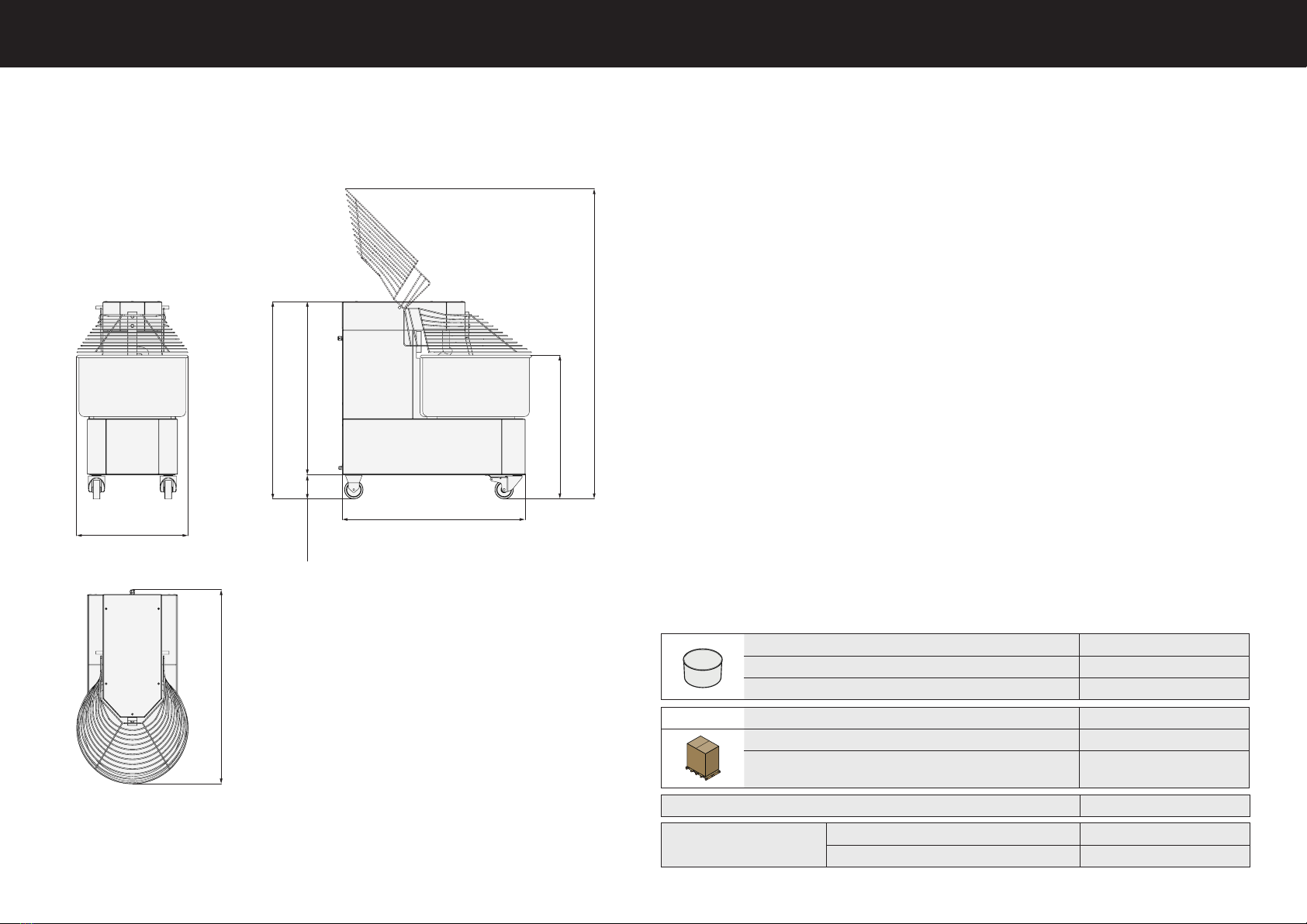
Ed. 0423 - 70702630 REV00 VENERE - Pre-installation 7
• Read this guide carefully before install-
ing the appliance, and keep it with care
in an accessible place for any future
consultation by the various operators.
• Moreover, the manual must always ac-
company the product through its life,
even in case of transfer.
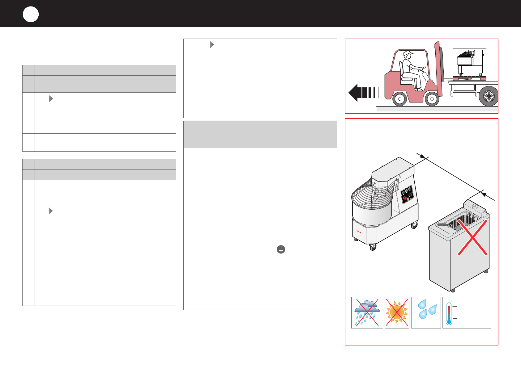
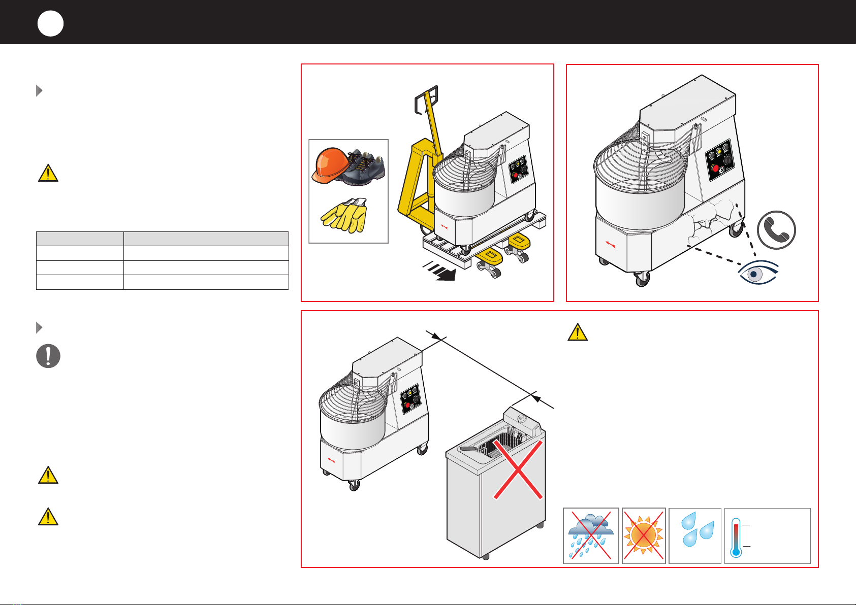
• Before any movement or installation,
check that the room is suitable and
systems comply with the installation
country standards and the specifica-
tions indicated on the appliance rating
plate.
• All installation, assembly and non-rou-
tine maintenance operations must
be performed exclusively by qualified
technicians that are authorised by the
Manufacturer, in compliance with the
regulations in force in the user country,
and with the regulations on systems
and work safety.
• Before performing any installation or
maintenance, disconnect the electric-
ity supply.
• Unauthorised actions, tampering or
modifications that do not follow the in-
formation provided in this manual can
cause damages, injuries or fatal acci-
dents and null and void the warranty.
• It is forbidden to install the product in
environments at risk of explosion.
• Installation or maintenance that fails
to comply with the instructions in this
manual may cause damage, injury or
fatal accidents.
• Do not obstruct the ventilation and ex-
haust holes of this or other equipment.
• Persons not involved with the appli-
ance installation may not pass through
or stand in the work area during appli-
ance assembly.
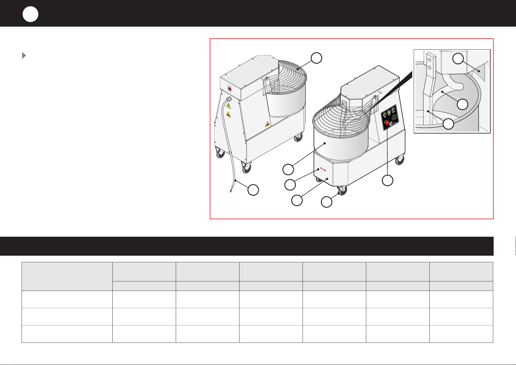
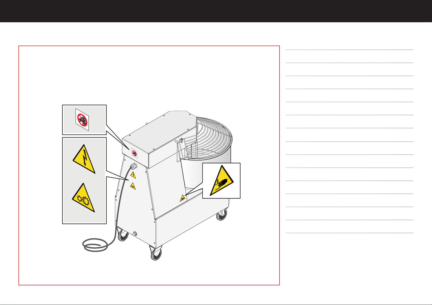
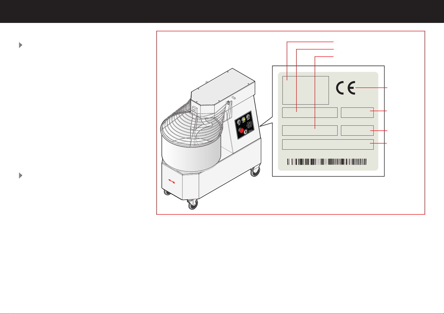
• The serial plate provides important
technical information. This is vital in
case of a request for maintenance or
repair of the equipment: please do not
remove, damage or modify it.
• These appliances are intended to be
used for commercial applications, for
example in restaurant kitchens, can-
teens, hospitals and commercial com-
panies such as bakeries, butcher shops,
etc., but not for the continuous and
mass production of food.
• To avoid risks, if the power cable is
damaged, it must be replaced by the
Retailer, its service agent or qualified
personnel.
• Failure to follow these regulations may
cause damage or even fatal injury, sub-
sequently invalidating the guarantee
and relieving the Manufacturer of all
liability.
• Noise levels lower than 70 dB.
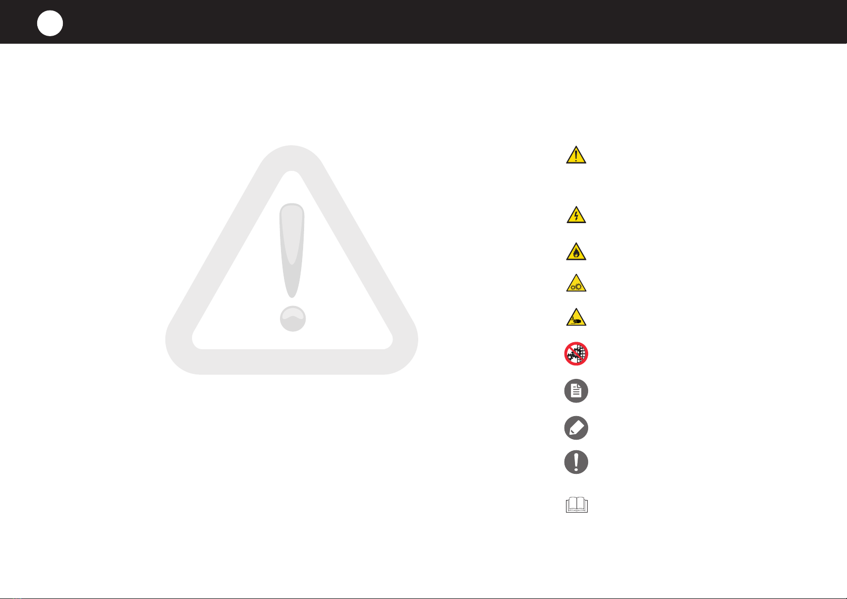
SYMBOLS USED IN THE MANUAL
AND ON THE LABELS APPLIED TO
THE MACHINE
Indicates that caution is required when perfor-
ming an operation described in a paragraph
that bears this symbol. The symbol also indi-
cates that maximum operator awareness is
required in order to avoid unwanted or dange-
rous consequences
Dangerous voltage
Risk of explosion
Gears danger
Hand crushing hazard
Do not remove the guard
Reference to another chapter where the
subject is dealt with in more detail.
Manufacturer’s tip
Manufacturer’s warning
Indicates that it is necessary to read carefully
the paragraph marked with this symbol befo-
re installing, using and maintaining the equi-
pment
SAFETY INSTRUCTIONS
3

8
Fig.4
Electricity
hazard
Gears danger
Hand crushing
hazard
Do not remove
the guard
Safety instructions
SYMBOLS APPLIED TO THE MACHINE NOTES
The company cannot be held liable for any print or transcrip-
tion errors, reserving the right to make changes where deemed
suitable without prior notice.
Partial reproduction without the Manufacturer’s consent is pro-
hibited. Measurements are purely indicative and not binding.
The original language used to prepare this manual is Italian: the
Manufacturer is not responsible for any translation/interpreta-
tion or print errors.

Ed. 0423 - 70702630 REV00 VENERE - Pre-installation 9
min.
500 mm
( in. 19,7)
Max 35°C
Max 70%
Min 5°C
Max 104°F
Min 41°C
Fig.5 Fig.6
Fig.7
min.
500 mm
( in. 19,7)
Max 35°C
Max 70%
Min 5°C
Max 104°F
Min 41°C
TRANSPORT
Fig.5
Equipped with personal protection equipment, trans-
port the appliance to the installation location.
Use a suitable vehicle capable of withstanding the
weight of the same.
Persons not involved with the appliance instal-
lation may not pass through or stand in the
work area during the transport of the appliance.
During the transport, pay particular attention to passing
through openings and/or doors.
VENERE model Weight
10 54 kg [119 lb]
20 78 kg [172 lb]
30 131 kg [289 lb]
PRELIMINARY OPERATIONS
Fig.6
Check that all the parts making up the appli-
ance are in good condition and without any
faults or breakages, if that is not the case, con-
tact the Dealer for the procedures to follow.
PACKAGING DISPOSAL
Before starting to install the appliance, dispose of the
packaging in compliance with the regulations in force in
the country of installation.
Caution, suffocation hazard! If left unattended,
packaging could be potentially dangerous for
both children and animals.
Caution, hindrance hazard! If left unattended,
packaging could hinder the assembly operations.
To reduce the risk of a fire, comply with the
stated minimum distances and install the ap-
pliance in fireproof rooms and not at risk of
explosion. The floor of the installation room must
also have a fireproof surface finish.
INSTALLATION
4

10
Fig.8
MADE IN ITALY
Mod. __________________
VOLT AC ________________ KW xx
2023
S/N ___________________________________
POSITIONING
Fig.7
Install the appliance in a room:
■ dedicated and suitable to the cooking of food;
■ having adequate air ventilation;
■ containing no flammable or explosive elements;
■ thatcomplieswith thecurrentregulationsonhealth
and safety and systems in your country;
■ is protected from the weather;
■ hasamaximumtemperatureofbetween+5°C(41°F)
and +35°C (95°F);
■ has a maximum humidity of 70%.
SERIAL NUMBER PLATE READING
Fig.8
The serial number is on the back of the appliance.
It provides important technical information that is vital
in case of a request for maintenance or repair of the ap-
pliance: please do not remove, damage or modify it.
Installation
Model
Name and address of the
Manufacturer
Electrical parameters
Absorption
Year of
construction
CE marking
Serial number

Ed. 0423 - 70702630 REV00 VENERE - Pre-installation 11
F - R - S - T...L:
AC 3N 400 V
T
N
S
R
Fig.9
ELECTRICAL CONNECTION
The electrical connection must be carried out
exclusively by qualified personnel after read-
ing the safety warnings at the beginning of the
manual.
Before installing the product, check that the
systems comply with the regulations in force
in the country of use and with the specifica-
tions indicated on the rating plate on the back
of the product.
Fig.9
The appliances have the power cable already installed;
a plug (not supplied) of suitable capacity must be fitted
to it. This operation must be carried out by qualified per-
sonnel.
For a correct electrical connection, the appliance must:
■ must be grounded to the mains (green-yellow
wire);
■ mustbeconnectedtoathermal differential switch
in compliance with the regulations in force (0.03A A
type);
■ must be connected to an omnipolar circuit break-
er allowing complete disconnection in overvoltage
III category conditions.
The Manufacturer accepts no liability for failure to com-
ply with the above.
Installation
earth
phases
The following pages show the electrical
diagrams: please refer to the one of the
specific model to connect.
This diagram is supplied for the replacement
of the connection cable with a new one, as the
machines come with the connection cable al-
ready fitted.
Fit a plug (not supplied) with a capacity suitable
for the power consumption of the product

12
17 mm
Fig.10 Fig.11
Fig.12
Installation
Fig.10 After connection, make sure that the cable:
■ is not hindering the passage of people or objects (e.g. trolleys on wheels);
■ is not crushed or bent;
■ is not placed near sharp edges or hot surfaces.
Extending the cable or using extension cables is not permitted.
If required, the cable must be replaced by the Dealer or its technical ser-
vice or by a person with similar qualifications to prevent any risk. The cable
must be replaced with one of equal characteristics and adequate for the
power consumption of the unit. For its replacement refer to the Fig.9
Electrical data tables on page 4
BELT TENSION ADJUSTMENT
The belt tension gradually loosens with use: this slows down or completely blocks the
rotation of the bowl, a problem not related to a malfunction of the motor.
Fig.11. In case of tank slowdown or blockage:
■ start the machine;
■ with a 17 mm wrench screw in slowly in a clockwise direction the tie rod locat-
ed on the rear panel of the machine;
■ when the bowl starts to rotate normally, stop screwing in the tie rod: the belt has
the correct tension again.
This operation can also be done by the end user if necessary.
CHAIN CONTROL
Check the tension of the chains and grease them every six months.
Fig.12. To access the chains, cut off power to the machine, wait for the capacitive
components to discharge (about 5 minutes) and remove the upper, rear and lower
protections.
Only an authorized and qualified technician can carry out this operation.

Ed. 0423 - 70702630 REV00 VENERE - Pre-installation 13
Installation | Electrical diagrams
Abbreviation Description
RP Contactor
M Motor
TM Transformer
F Fuse
LAMP Light
PT Thermal relay
MC Timer
STOP Emergency button
START Start button
RP Contactor coil
Bowl and spiral motor

14
PRETESTING AND FINAL INSPECTION
The product is checked and tested in the Manufacturer’s plant before being delivered to the customer.
The “production process check sheet” enclosed with it guarantees that each step in the production process, from assembly to packaging, was carefully checked from both the
operating and safety standpoints.
After installing the appliance, to complete the installation, carry out A, B, Cand D.
ACHECKING THE INSTALLATION IS CORRECT
Mark with a “√” all the boxes of the table below: this will confirm the installation is complete and correct.
√ POSITIONING CHECKS
Is the installation room adequate and compliant with regulations? (minimum, maximum temperature, etc.)
Is the appliance resting on a perfectly level floor?
Have the minimum distances stated been complied with?
√ ELECTRICAL CHECKS
Does the mains voltage match the data on the rating plate?
Do electric connections meet current regulations in the country of installation and follow the diagrams supplied?
√ MISCELLANEOUS
Does the user have all the documentation relative to the product?
FINAL OPERATIONS
5

Ed. 0423 - 70702630 REV00 VENERE - Pre-installation 15
Fig.13
Final operations
Fig.13 Make sure that the bowl rotates in the direction of the arrow. If this condition is not met, reverse two phases
(e.g. black cable with brown cable).
Start the appliance following the instructions in the “Use and Maintenance” manual annexed: monitor it during the
whole test and check that all the electrical components work properly.
The warranty MUST be activated at the end of the test.
IF NOT REGULARLY ACTIVATED, THE VALIDITY OF THE SAME STARTS FROM THE INVOICE DATE AND NOT FROM THE ACTU
AL INSTALLATION DATE.
CHECKING THE CORRECT DIRECTION OF ROTATION OF THE BOWL
CHECKING THE OPERATION AND FIRST STARTUP
WARRANTY ACTIVATION
B
C
D

This manual suits for next models
2
Table of contents
Other Cuppone Kitchen Appliance manuals

Cuppone
Cuppone Michelangelo User manual

Cuppone
Cuppone Michelangelo ML435 User manual

Cuppone
Cuppone Pizzaform PZF/30DS Operating manual

Cuppone
Cuppone Giotto GT110 User manual

Cuppone
Cuppone Leonardo VPR User manual

Cuppone
Cuppone Donatello DN 435 User manual

Cuppone
Cuppone Michelangelo User manual

Cuppone
Cuppone Michelangelo User manual

Cuppone
Cuppone Tiziano TZ420 Operating manual

Cuppone
Cuppone Gas G4 - 33 Operating manual