CYCMOTOR PHOTON User manual

photon
user manual

Dear PHOTON Owner,
We hope you enjoy this ebike kit as much as we do!
To make things easier for you, we've made a few useful notes here:
1. You can download the user manual and other general resources here: www.cycmotor.com/cycmotor-downloads.
2. Be sure to go through the user guide including the app and display section so that you can familiarise yourself with
how the system works.
3. Initial set-up
Initial set-up can be done on the display & does not require the app. Note that to change it on the display, you need to
enter the display’s settings by holding the MENU button down within the rst 15 seconds of the kit being powered on.
a. Check that your battery voltage is set up to match your battery pack.
b. Check that your wheel size is set to match your bike.
4. Race and Street Mode
You can switch between Race and Street mode on the display or on the app. Note that to change it on the display, you
need to enter into the display’s settings by holding the MENU button down within the rst 15 seconds of the kit being
powered on.
5. For changing advanced settings, please download the CYC Ride Control mobile app available on iOS and Android
devices. Contact our team for assistance if needed.
WARNING
Note the arrows on the connectors of peripherals to ensure you do not damage the pins upon installation.
Wires should not be pinched in between components or bent at.
Thanks for your support!
Cheers for now,
CYC Team

1
SAFETY & PRECAUTION
•General Safety
•Before the Ride
•Installation & Use
•Disclaimer
01
SPECIFICATIONS
•Description
•Specications
•Parts List
•Dimensions
•68/ 73/ 83mm version
•BB92 version
•100mm version
•120mm version
02
INSTALLATION
•Required Tools
•Operating Notice
•Preparing Your Frame
•Mounting Options
•Adjusting the Width of Bottom Bracket
•Assembly Instruction
•Torque Requirement for Bolts
•Wiring & Connection
03
CYC RIDE CONTROL
•Overview
•Disclaimer
•Privacy Policy
MAINTENANCE
•Error Codes
•General Maintenance
TERMS & CONDITIONS
•Warranty
•Purchases from a CYC Dealer
DOWNLOADS
04
SW102 DISPLAY GUIDE05
DS103 DISPLAY GUIDE06
07
08
09

Kindly read through the entire user manual. This manual contains
important information to reduce user risk as well as instructions for this
product’s proper use. Do not discard the manual but keep it for reference.
Note that the user’s personal safety remains the user’s responsibility and
that the user must contact CYCMOTOR LTD or an ocial product dealer
directly for any further guidelines or assistance.
Never interfere with the movable parts when the drive unit is connected
to a power supply. This could result in serious injury if the system is
accidently engaged.
This product is a powerful motor system that is dangerous for children
and must be handled by an adult at all times. Small components and
accessories may also present a choking hazard. Keep the motor system
and accessories out of reach from children.
All components and accessories may only be replaced with identical
components directly supplied by CYCMOTOR LTD or an ocial product
dealer. CYCMOTOR LTD cannot be held liable for any damages as a result
of using unapproved parts.
This product only complies with local, state, and federal regulations if
speed limits are set accordingly. Ensure that you have set up your e-bike
kit according to your local, state, and federal regulations when using and
registering this product on a public road/ area.
Ensure that the drive unit chain has proper tension. Incorrect tension
could cause jamming of the system and result in injury while riding.
Inspect the chain tension regularly.
Ensure that the chain is are properly lubricated.
When connecting a power supply, make sure that the power supply is
completely connected. Faulty connection could result in a short-circuit
and damage the controller or batteries.
Inspect all electrical wires and connectors for damage. Ensure that no
wires and/ or connectors are pinched in between the components or
bent at.
Secure all wires properly. Ensure that no loose wires are dangling from the
bike that could be jammed into any moving parts.
Before turning on the system, ensure that the throttle can be twisted
freely without friction and that the throttle can return to its original
position without restriction. This is to prevent any uncontrolled responses
from the system.
2

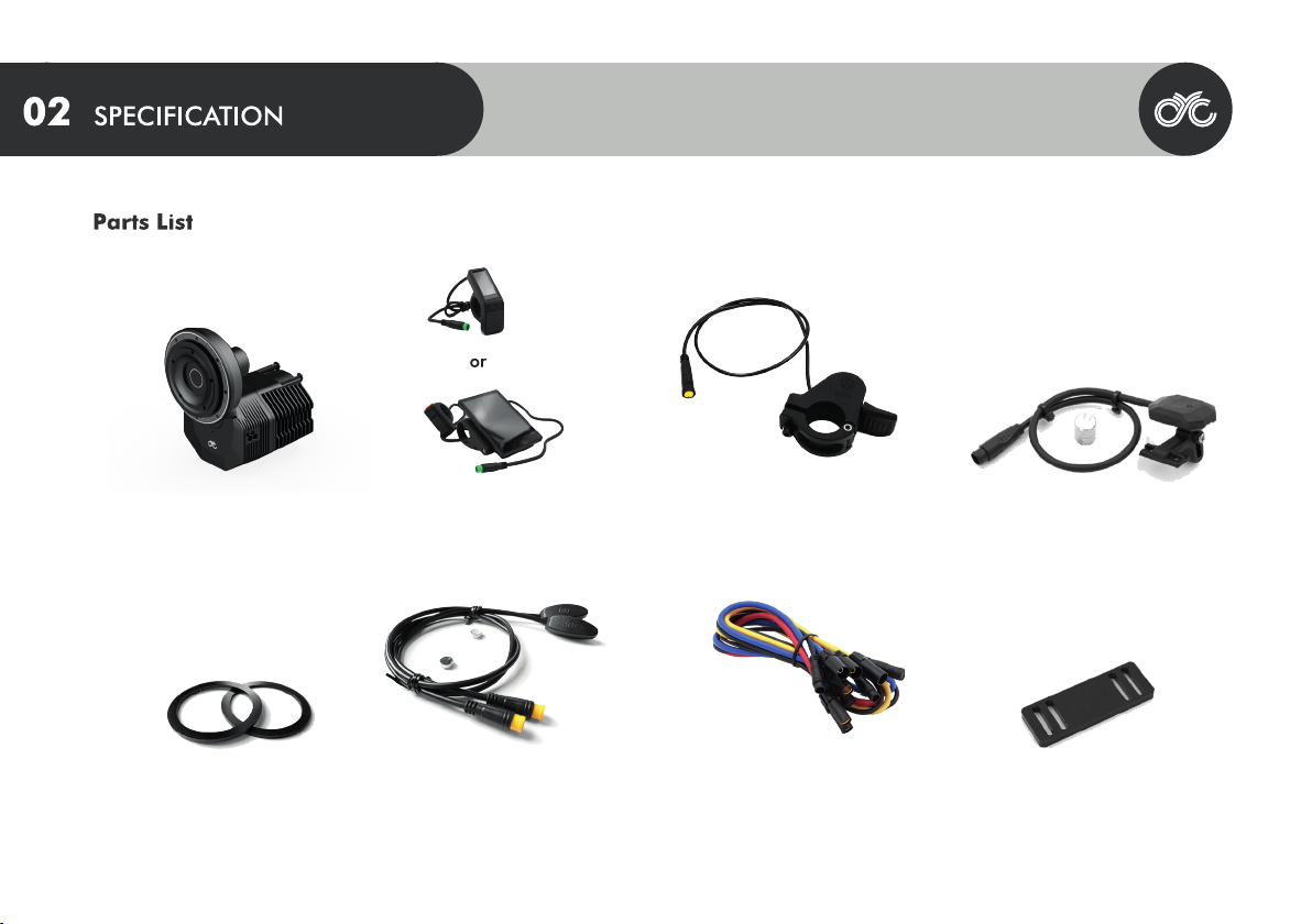
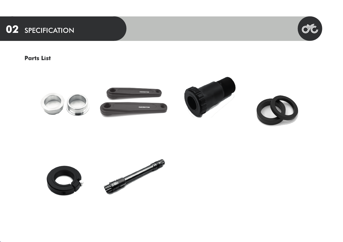
Do not install anything other than the parts and accessories that came
with this drive unit. Doing so could damage the product.
The drive system can be activated and deactivated by holding down the
POWER button the display.
Avoid changing the bike gear (note: this is dierent from the drive unit’s
assist level) while the drive unit is powering the bike. This may lead to
excessive wear on the chain and chainrings or other gear related failure.
When changing gear, it is advised to use human input only. After the gear
is changed, you may accelerate again with the throttle or continue using
the pedal assist system.
WARNING
Take o with the appropriate assist level & bike gear.
This product is splash proof and rain proof but NOT WATER PROOF. Do
not submerge it underwater.
Modications of any kind is not advised. Any issues with this product’s
performance or damages sustained to the product as a result of
modications will not be supported or warrantied by CYCMOTOR LTD or
any authorised product dealer. If this product or its components have
been found to be modied, warranty of the product may be limited in the
case where troubleshooting and/ or replacement may be needed.
If you require any more information or have any questions about the user
manual CYCMOTOR LTD disclaimer, please feel free to contact us via email
at support@cycmotor.com or call +852 3690 8938.
All the information contained in this manual is published in good faith
and for general informational purposes only. CYCMOTOR LTD does not
make any warranties about the completeness of this information and
encourages further inquries if needed. CYCMOTOR LTD will not be held
liable for any losses and/ or damages in connection with the use of this
product. The use of this product is at own risk.
Please contact CYCMOTOR LTD if you are unsure about the assembly
instructions or for any further assistance as CYCMOTOR LTD will be held
liable for any losses and/ or damages created by the assembly.
The control unit's hardware and software are under the GPL V3
opensource license. VESC® is a trademark and copyright of Mr. Benjamin
Vedder. More information can be found at
https://www.gnu.org/licenses/gpl-3.0.html. CYCMOTOR LTD's source
code can be found at https://github.com/CYC-MOTOR. Dierent rmware
can be loaded to this controller.
WARNING
Any issues with this product's performance or damages sustained to the
product as a result of loading unauthorised rmware, will not be
supported or warrantied by CYCMOTOR LTD or any authorised product
dealer.
3

4
36 - 52V
>300 RPM
750W (CYC XP6)
110 N.m. (CYC XP6)
Anodized Black
3.2kg
4.5kg
165mm or 175mm
FOC
Hall & Temp. Sensor
68-83mm, 100mm, 120mm BSA Threaded
>92mm Presst (with adaptor)
34T, 38T, & 50T
This product is an electric bike (ebike) drive unit kit which includes a programmed control unit and peripherals. This product is designed to be installed as a
conversion system to convert a standard bicycle into an electric bicycle.
*Bottom brackets not specied may be compatible. Contact CYCMOTOR LTD for more information before making a purchase if your bottom bracket type is
not listed above.
Max. Torque at Crank
Weight of Motor Unit

5
SW102 or DS103 Display Magnetic Bluetooth
Speed Sensor
Thumb ThrottlePHOTON motor assembly
Controller Extension Wires
(optional)
Mounting Support
Plate
Magnetic Brake Sensors
(optional)
Bottom Bracket Spacers

6
Left BB CupBB92 to BSA adaptors Crankarms with
crankarm bolts
SpindleRetaining Lock Ring
Spindle Spacers

7
BSA Threaded 68/73/83mm Version
O
P
Q
R
S
A
B
C
D
E
F
G
H
I
J
K
L
MM
N
96mm
128mm
150mm / 170mm/ 210mm
69mm
165mm / 175mm
47mm
60.5mm
83mm
13.3mm
54.8mm
64.6mm
77.8mm
88.9mm
104.4mm
80.1mm
95.6mm
30.55mm
14mm
200mm

8
O
P
Q
R
S
A
B
C
D
E
F
G
H
I
J
K
L
MM
N
96mm
128mm
150mm / 170mm/ 210mm
69mm
165mm / 175mm
52.5mm
55mm
92mm
13.3mm
60.3mm
70.1mm
83.3mm
94.4mm
109.9mm
94.6mm
110.1mm
30.55mm
14mm
220mm

S220mm
A96mm
128mm
150mm / 170mm/ 210mm
69mm
165mm / 175mm
55.5mm
52mm
100mm
13.3mm
63.3mm
73.1mm
86.26mm
97.4mm
B
C
D
E
F
G
H
I
J
K
L
MM
N112.9mm
O
P
Q
R
91.6mm
107.1mm
30.65mm
14mm
BSA Threaded 100mm Version
9

10
BSA Threaded 120mm Version
A
B
C
D
E
F
G
H
I
J
K
L
M
N
96mm
128mm
150mm / 170mm/ 210mm
69mm
165mm / 175mm
65.5mm
42mm
120mm
13.3mm
73.3mm
83.1mm
96.26mm
107.4mm
122.9mm
101.6mm
107.1mm
30.65mm
14mm
240mm
O
P
Q
R
S

Required Tools
Hex Keys ( 2.5mm & 10mm) Adjustable Wrench Crank Puller
Press Fit Bottom Bracket Removal Tools
Only for BB92 version
Ø44mm, 16 Notch Bottom Bracket Tool
11

RIGHT-HAND and LEFT-HAND sides are determined by the bike handle;
Right-hand corresponds to the right handle.
In order for this product to t on various dierent widths of bottom
brackets, there are several spacers that come with the kit. These spacers
are designed to provide the bottom brackets with necessary spacing
between the this product brackets.
Note that the spacers can be adjusted to accommodate dierent chain
lines as needed.
Before you begin, ensure that you have removed the original crankset
and bottom bracket from the bicycle frame. This includes any bearings,
bottom bracket cups, inserts, and/ or adaptors that might have been
tted. Clean up any grease and/ or debris from your frame's bottom
bracket shell and wipe o any excess dirt from your frame around the
areas where the drive unit and its peripherals will be installed.
Preparing Your Frame
This product can be mounted in any position around the bicycle frame's
bottom bracket shell that supports the drivetrain's movement without
obstruction. The chainring assembly together with your bicycle chain
must be able to move freely and not come into contact with other
components or areas on the bicycle frame.
Mounting Options
Operating Notice
The motor body must be supported against either the bicycle frame or
supporting structures in order to prevent the motor body from
movement during use.
WARNING
12

Assembly Instruction
▪Install the chainring assembly to the motor unit.
▪The chainring assembly splines onto the gear of the motor unit.
▪The retaining cap can be threaded on with the provided tool. Please take note of the tightening direction.
13

▪Insert the motor so that the back of the motor sits closest to the drive side of the bottom bracket.
▪Ensure that the motor is mounted from the right hand side of the bicycle frame.
14
Assembly Instruction

▪Take note of the clearance between the chainstay of the bike and the motor unit. Sometimes the motor unit will need to be spaced out
additionally to create space for the chainring and chainstay.
15
Assembly Instruction

▪The PHOTON motor is designed for an eective BB width of 83mm. Thus, the required length needed for a 68 or 73mm bottom bracket
needs to be taken up by the provided bottom bracket spacers.
16
Assembly Instruction

▪When inserting the left BB cup with spacers, please ensure that the A-frame support is added to the left BB cup rst so that it sits
against the tool side of the BB cup. Then place the A-frame in the cutout of the motor housing while inserting the left BB cup into the
bottom bracket. Tighten by hand only. If done correctly, the A-frame support should be ush with the cutout of the motor body.
17
Assembly Instruction

▪Place the 8mm & 9mm spacers in the remaining open space of the motor cover and thread the two M4 screws through them and into
the body. Securely tighten these screws.
18
Assembly Instruction
Other manuals for PHOTON
1
Table of contents
Other CYCMOTOR Bicycle Accessories manuals

CYCMOTOR
CYCMOTOR X1 Stealth User manual

CYCMOTOR
CYCMOTOR X1 STEALTH GEN 3 User manual

CYCMOTOR
CYCMOTOR X1 PRO User manual

CYCMOTOR
CYCMOTOR PHOTON User manual

CYCMOTOR
CYCMOTOR APT 750c Display User manual

CYCMOTOR
CYCMOTOR X1 STEALTH GEN 3 User manual

CYCMOTOR
CYCMOTOR X1 PRO User manual

CYCMOTOR
CYCMOTOR DS103 User manual

CYCMOTOR
CYCMOTOR X1 PRO User manual

CYCMOTOR
CYCMOTOR PHOTON User manual