CYCMOTOR X1 PRO User manual

14S Controller Version 2.0
CYC MOTOR LTD
X1 PRO
USER MANUAL

2
01 SAFETY
General Safety
Operating Safety
Before the Ride
Proper Use
02 SPECIFICATION
General Specication
Variants and Dimensions
68 - 83mm Version
100mm Version
120mm Version
Motor & Controller
Part list
03 INSTALLATION
Required tools
Adjusting the Width of the Bottom Bracket
Mounting the X1 pro to the frame
PAS Sensor Installation
Mounting the Crankset (Gear Version)
Mounting the Crankset (Chain Version)
Wiring and Connection
04 MAINTANENCE
General Maintenance
Gear Version
05 MOBILE APP
Getting Started
Dashboard
Preset Modes
Trip Planner
Data Logger
06 DISPLAY
07 QUICK START
08 TERMS AND CONDITIONS
00 TABLE OF CONTENTS

3
Please read through the entire user manual as it con-
tains important information for the X1 PRO’s proper
usage and reduced user risk. Keep the manual for
reference.
Your personal safety is your own responsibility. If you
have any questions or misunderstanding, please con-
tact your X1 PRO dealer or component manufacturer.
Some X1 PRO accessories may present a choking
hazard to small children. Keep these accessories away
from children.
RIGHT-HAND and LEFT-HAND sides are determined by
the bike handle, RIGHT-HAND corresponds to the right
handle.
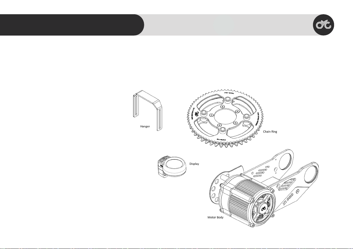
All components attached to the drive unit may be
replaced only with identical components or compo-
nents specically approved by the bicycle manufac-
turer. This protects the drive unit against overload and
damage.
The X1 PRO does not comply with EU or US e-bike regu-
lations, it is for off-road and private-track use only. User
please follow all local, state and federal regulations
when registering and using the drive unit.
Operating Safety
Before the ride:
Check that the drive unit chain has the proper tension.
Before connecting any power supply, make sure the
power supply is completely connected.
Make sure that no loose wire is dangling from the bike
that could be jammed into any moving parts.
Before turning on the system, ensure that the throttle
can be twisted freely without friction, that the throttle
can return to its original position and double check
that the throttle is restored to its ORIGINAL POSITION.
Ensure that the chains are properly lubricated.
Check the chains regularly for proper tension.
Check electrical wires and plugs to see if there is any
damage.
01 SAFETY 01 General Safety

4
Proper Use:
Do not install anything other than the parts and ac-
cessories that came with the drive unit, doing so could
damage the product,
Never interfere with the movable parts when the drive
unit is connected to power supply.
The drive system can be activated by holding down
the on/off button on the display.
Do not change the bike gear (note: this is different
from the electronic gear in your app) when the drive
unit is powering the bike, this will lead to excessive
wear on chain and chain rings leading to chain failure.
To change gear, please use only your own pedaling
power. After the gear is changed, you may accelerate
again with the throttle.
Take off with the appropriate gear; choose the gear
you can power at take off, then slowly twist the throttle
to reach the desired power.
Overloading the drive unit for an extended period of
time will damage the materials used.
The X1 PRO is splash proof, rain proof but not water
proof, do not submerge it underwater or ride through
streams.
01 SAFETY 02 Operating Safety

5
General
Rated Voltage 36 - 72V D.C.
Max. rpm > 180 rpm
Rated Power 3000W
Max Torque ≥ 180 N.m.
Overall efciency ≥ 80%
Bottom bracket BSA / PressFit
Color Black
Total Weight 3.5kg
Bracket Materials 7075-T6
Crank Arm 7075-T6 170mm
Q Factor 190mm - 210mm
Compatibility Bike frame with standard BB
thread and width of 68 / 73/
83 / 100, or press t frames
with 41mm diameter with
width of 92mm or less
Gearbox
First-stage 1:6 hardened steel planetary
Second-stage 1:6 72T Chainring
11:63 63T Chainring
11:53 53T Chainring
Overall reduction ratio ~1:36
02 SPECIFICATION 01 General Specication

6
Parts List
Common Parts
Motor body (includes controller)
Chainring
Display
Thumb Throttle
1 to 4 Controller Wire
E-Brakes
219H Chain
Bike Hanger (83mm or 100mm)
02 SPECIFICATION 02 Variants and Dimensions

7
83mm BSA Torque Sensing Version
Dimensions
A: 94mm
b: 253mm
c: 190mm
D: 34mm
e: 110mm
F: 178.6mm
G: 83mm
H: 190mm
83mm BSA Torque Sensing Version Extra Parts
• 83mm BSA Torque Sensing Version Crank Set
• 3mm, 5mm, 7mm Spacers
02 SPECIFICATION 03 Variants and Dimensions

8
92mm PressFit Torque Sensing Version
Dimensions
A: 94mm
b: 253mm
c: 190mm
D: 34mm
e: 110mm
F: 178.6mm
G: 92mm
H: 190mm
92mm PressFit Torque Sensing Version Extra
Parts
• 92mm PressFit Torque Sensing Version Crank Set
• 1mm, 2mm Spacers
02 SPECIFICATION 04 Variants and Dimensions

9
100mm BSA Torque Sensing Version
Dimensions
A: 94mm
b: 253mm
c: 190mm
D: 34mm
e: 110mm
F: 178.6mm
G: 100mm
H: 210mm
100mm BSA Torque Sensing
Version Extra Parts
• 100mm BSA Torque Sensing Version Crank Set
• Extra Plate & Spacers
02 SPECIFICATION 05 Variants and Dimensions

10
83mm BSA Cadence Sensor Version
Dimensions
A: 94mm
b: 253mm
c: 190mm
D: 34mm
e: 110mm
F: 178.6mm
G: 83mm
H: 190mm
83mm BSA Cadence Sensor Version Extra
Parts
• 83mm BSA Cadence Sensor Version Crank Set
• 3mm, 5mm, 7mm Spacers
02 SPECIFICATION 06 Variants and Dimensions

11
100mm BSA Cadence Sensor Version
Dimensions
A: 94mm
b: 253mm
c: 190mm
D: 34mm
e: 110mm
F: 178.6mm
G: 100mm
H: 210mm
100mm BSA Cadence Sensor Version Extra
Parts
• 100mm BSA Cadence Sensor Version Crank Set
• Extra Plate & Spacers
02 SPECIFICATION 07 Variants and Dimensions

12
Motor
Motor type In-runner
Stator O.D. 80mm
Stator I.D. 46.4mm
Thickness 40mm
Stator lamination 0.2mm
Magnet N45SH (>150°C)
Wiring 0.7mm
Efciency ≥ 90%
Maximum RPM ≈ 6500rpm
Rated Torque 4N.m.
Transparent cover Tempered glass
Epoxy sealed Yes
Controller
Chipset Spintrol
Rated Voltage 36-72V D.C.
Max. input current 65A
Bluetooth BLE
Mobile App IOS / Android
Throttle Control mode Current / Power / rpm
PAS Torque simulation 9-Axis gyroscope
Mounting position Integrated between bracket /
mounted separately
02 SPECIFICATION 08 Motor & Controller

13
WrenchHex Keys
3mm hex key for screws
&
10mm hex key for crank screws
Wire Cutter Press Fit Bottom
Bracket Removal Tools
Crank Puller
for removing the crank arms
Cutter Bottom Bracket Tool
for installing and removing the 20
splined cover caps
Bottom Bracket Tool
for installing and removing
the bottom bracket caps,
the tool needs to have an
opening on its end as shown
03 INSTALLATION 01 Required Tools

14
Mounting Options for Controller
The controller can be mounted right below the bottom
bracket or mounted under the seat.
NOTE: The controller comes pre-assembled at the bot-
tom bracket.
Adjusting the Width of the Bottom Bracket
In order for the X1 PRO to t on all different widths of
bottom brackets, there are several spacers that come
with the pack, these spacers are designed to provide
the 68mm and 73mm bottom brackets with necessary
spacing between the X1 PRO brackets.
The preferred mounting set-ups are shown on the right
for 68mm and 73mm bottom brackets.
Before mounting the motor body to your bike frame,
the existing crank system and bottom bracket must be
removed.
68mm bottom bracket requires a 7mm and a 5mm spacer
on the left and a 3mm spacer on the right as shown
73mm bottom bracket requires a 7mm spacer on
the left and a 3mm spacer on the right as shown
03 INSTALLATION 02 Adjusting the Width of
the Bottom Bracket

15
Mounting the Cadence Sensor
The Cadence Sensor is to be installed on the right side
of the X1PRO.
The outlet of the PAS sensor passes through the internal
side of the plate and connects to the controller via the
3-pin socket at the controller end.
03 INSTALLATION 03 Cadence Sensor Installation

16
1. Line up the motor body with your bike at the
bottom bracket. (Place a 3mm spacer between
the right mounting plate and the bottom bracket if
you have a 68mm wide bottom bracket)
2. Thread in the right mounting bracket through the
rear hole on the right mounting plate (and the
3mm spacer if required) into the bike’s bottom
bracket. Note that the thread is in reverse.
3. If you have a 68mm wide bottom bracket, use
a 5mm and a 7mm spacer, if you have a 73mm
wide bottom bracket, use a 3mm and a 7mm
spacer. Place the spacers between the left side of
the bike’s bottom bracket and the left mounting
plate.
4. Thread in the left mounting bracket through the
rear hole on the LEFT mounting plate (and the
spacers) into the bike’s bottom bracket.
Mounting the BSA Crank Versions to the Bike Frame
03 INSTALLATION 04 Mounting the X1 PRO
for BSA Versions

17
5. Hang your bike chain on the spindle.
6. Put on the golden chain, it lies on the outside of
the bike’s chain.
7. Put on the crank. Your bike chain should go on the
inner chainring and the golden chain should go on
the outer chainring. (If you nd it difcult to install
the golden chain, please unscrew the 5 counter-
sunk screws on the chainring, put on the golden
chain and then screw on the screws again.)
8. Put on the left crank arm and screw on with crank
bolt.
03 INSTALLATION 05 Mounting the X1 PRO
for BSA Versions

18
1. Line up the motor with your bike at the bottom bracket. (Place
the neccessary spacers between the LEFT mounting plate and
the bottom bracket if there is a gap between the two parts.)
2. Insert in the LEFT mounting bracket (The one with a wire coming
out) through the rear hole on the LEFT mounting plate into the
bike’s bottom bracket. Please use the presst installation tools.
3. Thread in the RIGHT mounting bracket through the rear hole on
the RIGHT mounting plate into the bike’s bottom bracket.
4. Insert the spindle from the RIGHT side of the rear mounting
bracket hole through to the LEFT side of the rear mounting
bracket hole.
Mounting the PressFit Crank Versions to the Bike Frame
03 INSTALLATION 06 Mounting the X1 PRO
for PressFit Versions

19
5. Screw on the left cap.
6. Hang your bike chain on the spindle.
7. Put on the golden chain, it lies on the outside of the bike’s chain.
8. Put on the crank. Your bike chain should go on the inner chain-
ring and the golden chain should go on the outer chainring. (If
you nd it difcult to install the golden chain, please unscrew the
5 countersunk screws on the chainring, put on the golden chain
and then screw on the screws again.)
9. Screw on the right cap.
10. Put on the right crank arm and screw on with crank bolt.
11. Put on the left crank arm and screw on with crank bolt.
03 INSTALLATION 07 Mounting the X1 PRO
for PressFit Versions

20
Install the Tensioner on to the X1 PRO
The spacers next to the sprocket should measure
25.5mm,use a M5*30mm countersunk screw for the
spacer.
The spacer for the full carbon cover should measure
31.35mm, use a M5*40mm countersunk screw for the
spacer.
Assemble the tensioner as shown on the right.
Make sure that the arm of the spring faces down-
wards.
Should the tensioner ever comes apart during installa-
tion, reassemble it according to the diagram below.
03 INSTALLATION 08 Install the Tensioner
on to the X1 PRO
Other manuals for X1 PRO
2
Table of contents
Other CYCMOTOR Bicycle Accessories manuals

CYCMOTOR
CYCMOTOR APT 500c Display User manual

CYCMOTOR
CYCMOTOR PHOTON User manual

CYCMOTOR
CYCMOTOR PHOTON User manual

CYCMOTOR
CYCMOTOR PHOTON User manual

CYCMOTOR
CYCMOTOR X1 PRO User manual

CYCMOTOR
CYCMOTOR DS103 User manual

CYCMOTOR
CYCMOTOR APT 750c Display User manual

CYCMOTOR
CYCMOTOR X1 STEALTH GEN 3 User manual

CYCMOTOR
CYCMOTOR X1 STEALTH GEN 3 User manual

CYCMOTOR
CYCMOTOR X1 Stealth User manual