CYCMOTOR X1 PRO User manual

X1 PRO GEN 3
User Manual
CYC MOTOR LTD
support@cycmotor.com +852 3690 8938

1
©2023 CYC MOTOR LTD
X1 PRO GEN 3 USER MANUAL
TABLE OF CONTENTS
SAFETY & PRECAUTION........................................................................3
General Safety ....................................................................................................................................3
Before the Ride...................................................................................................................................3
Installation & Use ...............................................................................................................................4
Disclaimer...........................................................................................................................................4
Warning............................................................................................................................................... 5
TECHNICAL SPECFICIATIONS .............................................................6
Description .........................................................................................................................................6
General ............................................................................................................................................... 6
Motor...................................................................................................................................................6
Controller............................................................................................................................................ 6
Gearbox ..............................................................................................................................................7
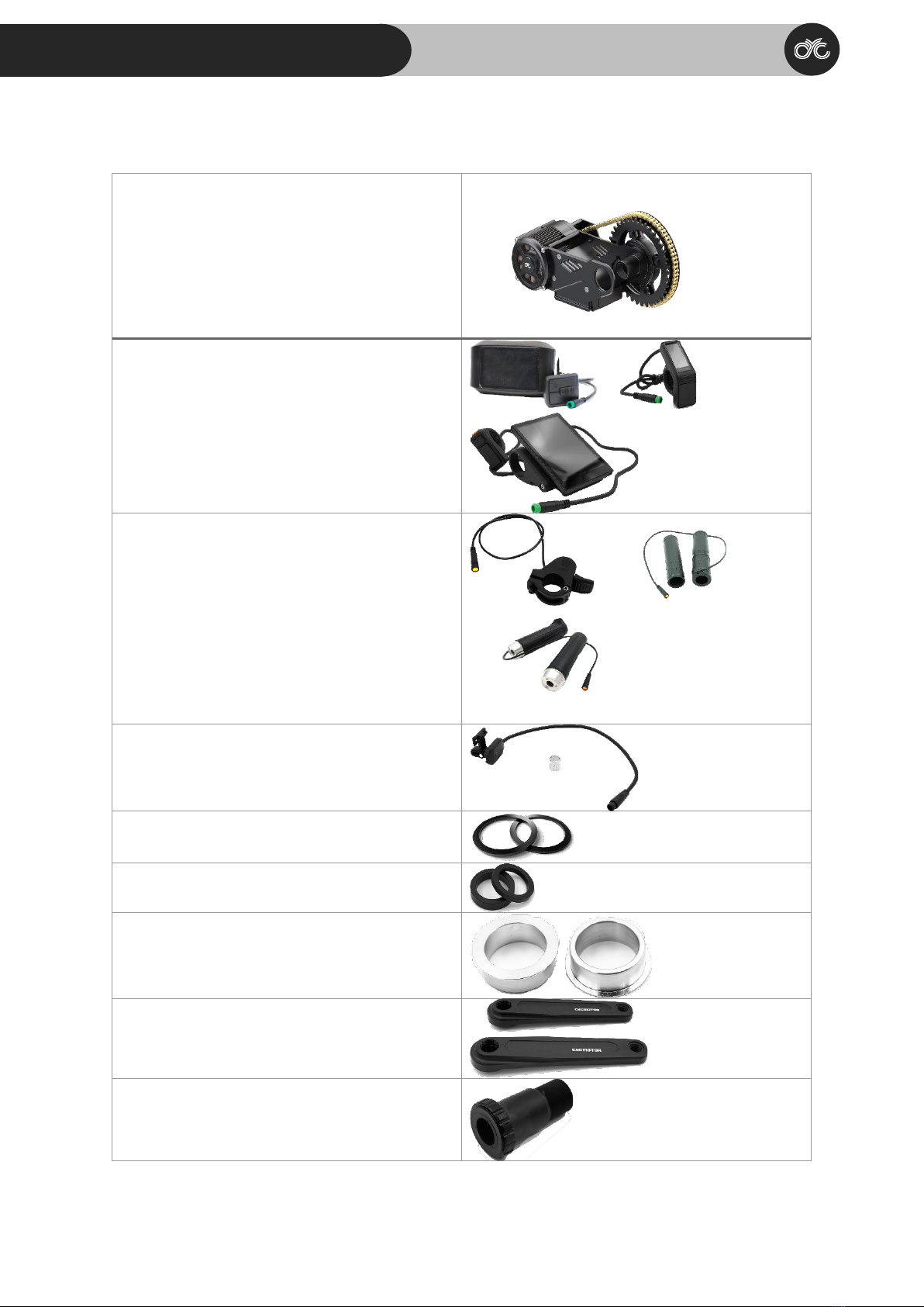
Parts List............................................................................................................................................. 8
Dimensions....................................................................................................................................... 10
BSA Threaded 68/73/83mm Version............................................................................................ 10
BSA Threaded 100mm Version .................................................................................................... 11
BSA Threaded 120mm Version .................................................................................................... 12
BB92 Version................................................................................................................................. 13
INSTALLATION....................................................................................... 14
Required Tools ................................................................................................................................. 14
Operating Notice.............................................................................................................................. 15
Mounting Options for Controller ..................................................................................................... 15
Adjusting the Width of the Bottom Bracket .................................................................................... 15
Installation of 68/73/83mm version ................................................................................................ 17
Installation of 100mm & 120mm version ........................................................................................ 21
Installation of BB92 version............................................................................................................. 25
Mounting the Hanger ....................................................................................................................... 29
Wiring & Connection......................................................................................................................... 31
MOBILE APP & DISPLAY.....................................................................32

2
©2023 CYC MOTOR LTD
X1 PRO GEN 3 USER MANUAL
GENERAL MAINTENANCE ..................................................................33
Torque Requirement for Bolts ......................................................................................................... 34
Bolt Specifications ........................................................................................................................... 34
WARRANTY.............................................................................................35
PURCHASES FROM A CYC DEALER ................................................35
CONTACT INFORMATION...................................................................35
PRIVACY POLICY...................................................................................36
INFORMATION COLLECTION AND USE..........................................36

3
©2023 CYC MOTOR LTD
X1 PRO GEN 3 USER MANUAL
SAFETY & PRECAUTION
General Safety
Kindly read through the entire user manual. This manual contains important information to
reduce user risk as well as instructions for this product’s proper use. Do not discard the manual
but keep it for reference.
Note that your personal safety remains your responsibility and that the user must contact
CYCMOTOR LTD or their official product dealer/distributor directly for any further guidelines or
assistance.
Never interfere with the movable parts when the drive unit is connected to a power supply. This
could result in serious injury if the system is accidently engaged.
This product is a powerful motor system that is dangerous for children and must be handled by an
adult at all times. Small components and accessories may also present a choking hazard. Keep the
motor system and accessories out of reach from children.
All components and accessories may only be replaced with identical components directly
supplied by CYC MOTOR LTD or an official product dealer/distributor. CYC MOTOR LTD cannot be
held liable for any damages as a result of using unapproved parts.
This product only complies with local, state, and federal regulations if speed limits are set
accordingly. Ensure that you have set up your X1 Pro kit according to your local, state, and federal
regulations when using and registering this drive unit on a public road/area.
Before the Ride
Ensure that the drive unit chain has the proper tension. Incorrect tension could cause jamming of
the system and result in injury while riding. Inspect the chain tension regularly.
Ensure that the chains are properly lubricated. Cleaning and lubricating your chain with a regular
bicycle chain cleaner, is advised regularly.
When plugging in your kit, please ensure that your peripherals are connected properly as faulty
connection could result in damage of the controller or batteries.

4
©2023 CYC MOTOR LTD
X1 PRO GEN 3 USER MANUAL
Inspect all electrical wires and plugs for damage regularly.
Secure all wires properly. Ensure that the throttle can bet twisted freely without friction and that
the throttle can return to its original position without restriction. This is to prevent any
uncontrolled response of the system.
Installation & Use
Do not install anything other than the parts and accessories that came with this drive unit. Doing
so could damage the product.
The drive system can be activated and deactivated by holding down the ON/OFF button of the
display.
Avoid changing the bike gear (note: this is different from the drive unit’s assist level) while the
drive unit is powering the bike. This may lead to excessive wear on the chain and chain rings or
other gear related failure. When changing gears, use human input only. After the gear is changed,
you may accelerate again with the throttle or continue using the PAS.
Take off with the appropriate assist level and bike gear.
This product is splash proof and rain proof but not waterproof. Do not submerge it underwater.
Disclaimer
If you require any more information or have any questions about the user manual disclaimer,
please feel free to contact us via email at support@cycmotor.com or call +852-3690-8938.
All the information contained in this manual is published in good faith and for general
informational purposes only. CYC MOTOR LTD does not make any warranties about the
completeness of this information and encourages further inquiries If needed. CYC MOTOR LTD will
not be held liable for any losses and/ or damages in connection with the use of this product. The
use of this product is at own risk.

5
©2023 CYC MOTOR LTD
X1 PRO GEN 3 USER MANUAL
Please contact CYC MOTOR LTD if you are unsure about the assembly instructions or for any
further assistance as CYC MOTOR LTD will be held liable for any losses and/ or damages created by
the assembly.
The control unit’s hardware and software are under the GPL V3 open-source license. VESC® is a
trademark of Benjamin Vedder. More information can be found at www.gnu.org/licenses/gpl-
3.0.html. CYCMOTOR LTD’s source code can be found at www.github.com/CYC-MOTOR. Different
firmware can be loaded to this controller.
Warning
Any issues with this product’s performance or damages sustained to the product as a result of
loading unauthorized firmware, will not be supported, or warrantied by CYC MOTOR LTD or any
authorised product dealer.
Modifications of any kind is not advised. Any issues with this product’s performance or damages
sustained to be the product as a result of modifications will not be supported or warrantied by
CYC MOTOR LTD or any authorized product dealer. If the product or its components have been
found to be modified, warranty of the product may be limited in the case where troubleshooting
and/ or replacement may be needed.

6
©2023 CYC MOTOR LTD
X1 PRO GEN 3 USER MANUAL
TECHNICAL SPECFICIATIONS
Description
This product is a high-powered electric bike (ebike) drive unit kit which includes a programmed
control unit and peripherals. This product is designed to be installed as a conversion system to
convert standard bicycles into electric bicycles.
General
Rated Nominal Voltage
36V – 72V
Max. RPM at Crank
Approx. 350 RPM
Rated Power
3500W (CYC X6) / 5000W (CYC X12)
Colour
Anodized Black
Weight of Motor & Controller
3.8 kg
Total Weight with Crank set & BB
5.6 kg
Bracket Materials
7075-T6
Crank Arm Length
165mm or 175mm
Q Factor
190 for BB83
Control Method
FOC
Motor Sensor
Hall & Temp. Sensor
Chain ring
32T with 52T motor chainring
38T with 63T motor chainring
40T with 72T motor chainring
Compatibility
68-83mm, 100mm, 120mm BSA Threaded
>109mm Pressfit (with adapter)
Motor
Motor Type
In-runner motor
No-load Motor Kv
150
Stator Lamination
0.35mm
Magnet
N45UH (>180 °C)
Efficiency (at 2N.m.)
92% at 70N.m.
Peak RPM
12,600 RPM
Epoxy sealed
Black Epoxy Potted Stator
Controller
Type
CYC X6 / X12 Controller
Nominal Voltage
24V – 86V
Max. Input Current
65A (CYC X6 Controller) 110A (CYC X12
Controller)
Bluetooth
Connectivity via speed sensor
Mobile App
CYC Ride Control App for iOS & Google Play

7
©2023 CYC MOTOR LTD
X1 PRO GEN 3 USER MANUAL
Mounting Position
Integrated between bottom bracket /
mounted separately
Gearbox
First Stage Reduction
Hardened steel sun & ring gear with brass
planetary gears 1:6
Second Stage Reduction
53T:11T = 4.82
63T:11T = 5.73
72T:11T = 6.55
Overall Reduction 1:28.9 (11/53T)
1:34.4 (11/63T)
1:39.3 (11/72T)

8
©2023 CYC MOTOR LTD
X1 PRO GEN 3 USER MANUAL
Parts List
X1 Pro Gen 3 Motor Assembly with Chainring
750c, SW102 or DS103 Display
or or
Thumb, Half-Twist or Full Throttle
or or
Magnetic Bluetooth Speed Sensor
Bottom Bracket Spacers
Spindle Spacers
BB92 to BSA adapters
Crankarms with Crankarm Bolts
Left Bottom Bracket Cup

9
©2023 CYC MOTOR LTD
X1 PRO GEN 3 USER MANUAL
Mounting Hanger
Retaining Lock Ring
Spindle
(OPTIONAL) Magnetic Brake Sensors
(OPTIONAL) Controller Extension Wires

10
©2023 CYC MOTOR LTD
X1 PRO GEN 3 USER MANUAL
Dimensions
BSA Threaded 68/73/83mm Version
A
94mm
B
253mm
C
140mm / 165mm / 190mm
D
177.9mm
E
165mm / 175mm
F
82.9mm
G
62.5mm
H
83mm
I
47.5mm
J
55.3mm
K
70.6mm
L
81.81mm
M
91.6mm
N
107.1mm

11
©2023 CYC MOTOR LTD
X1 PRO GEN 3 USER MANUAL
Dimensions
BSA Threaded 100mm Version
A
94mm
B
253mm
C
140mm / 165mm / 190mm
D
177.9mm
E
165mm / 175mm
F
91.4mm
G
54mm
H
100mm
I
56mm
J
63.8mm
K
79.1mm
L
90.3mm
M
100.1mm
N
115.6mm

12
©2023 CYC MOTOR LTD
X1 PRO GEN 3 USER MANUAL
Dimensions
BSA Threaded 120mm Version
A
94mm
B
253mm
C
140mm / 165mm / 190mm
D
177.9mm
E
165mm / 175mm
F
101.4mm
G
44mm
H
120mm
I
66mm
J
73.8mm
K
89.1mm
L
100.3mm
M
110.1mm
N
125.6mm

13
©2023 CYC MOTOR LTD
X1 PRO GEN 3 USER MANUAL
Dimensions
BB92 Version
A
94mm
B
253mm
C
190mm
D
177.9mm
E
165mm / 175mm
F
79.4mm
G
66mm
H
92mm
I
44mm
J
52.3mm
K
67.1mm
L
78.6mm
M
97.1mm
N
112.6mm

14
©2023 CYC MOTOR LTD
X1 PRO GEN 3 USER MANUAL
INSTALLATION
Required Tools
Hex Keys (3mm & 8mm)
Adjustable Wrench
PressFit Bottom Bracket Removal Tools (Only
for BB92 version)
16 Notch Bottom Bracket Tool
Crank Puller (for disassembly)

15
©2023 CYC MOTOR LTD
X1 PRO GEN 3 USER MANUAL
Operating Notice
RIGHT-HAND and LEFT-HAND sides are determined by the bike handle; Right-hand corresponds to
the right handle.
Mounting Options for Controller
The CYC X6 controller can be mounted below the bottom bracket (pre-assembled by default) or
mounted elsewhere on the bicycle frame at the user’s discretion using controller extension wires
that can be selected upon purchase or bought separately from the CYC online store or an
authorized dealer.
NOTE: The controller comes preassembled at the bottom bracket between the mounting plates.
Adjusting the Width of the Bottom Bracket
In order for the CYC kit to fit on various different widths of bottom brackets, there are several
spacers that come with the kit. These spacers are designed to provide the bottom brackets with
necessary spacing between the motor brackets.
Please note that the spacers can be adjusted to accommodate different chainlines as needed.
The preferred mounting set-ups are shown on the next page for 68mm and 73mm bottom
brackets. Note that the spacers can be adjusted to accommodate different chain lines as needed.
Before you begin, ensure that you have removed the original crank set and bottom bracket from
your frame. This includes any bearings and/or cups that might have been fitted previously. To
install your CYC kit, you will need a clean bottom bracket shell on your frame.

16
©2023 CYC MOTOR LTD
X1 PRO GEN 3 USER MANUAL
*68mm bottom brackets require a 7mm and a 5mm spacer on the left (non-drive side) and a 3mm
spacer on the right (drive side) as shown.
*73mm bottom brackets require a 7mm & 3mm spacer on the left (non-drive side) and no spacer
on the right (drive side) as shown.

17
©2023 CYC MOTOR LTD
X1 PRO GEN 3 USER MANUAL
Installation of 68/73/83mm version
1.
a. Remove the bolts as indicated within the circles in order to loosen the left (non-
drive) side mounting bracket.
b. Loosen the bolt as indicated within the square Do not remove completely.
c. Gently swing the left mounting bracket upward and line up the motor body with
your frame’s bottom bracket shell.
d. Insert the right (drive) side of the motor into the frame’s bottom bracket shell.
e. Once positioned into the frame’s bottom bracket, swing the left mounting bracket
back down and retighten all loosened/ removed bolts.
2.
a. Line up the 3, 5, and/ or 7mm bottom bracket spacer/s provided outside the
adapter bracket plate on the left (non-drive) side of the frame (spacer guidelines
mentioned below).
b. Thread the left (non-drive) side bottom bracket cup into the frame’s bottom
bracket shell through the spacer/s and the mounting bracket. Rotate clockwise.
i. For a 68mm bottom bracket shell, place the 5mm & 7mm bottom bracket
spacer over the left (non-drive) side bottom bracket cup before inserting it
into the frame’s bottom bracket shell.
ii. For a 73mm bottom bracket shell, place the 3mm & 7mm bottom bracket
over the left (non-drive) side bottom bracket cup before inserting it into
the frame’s bottom bracket shell.
iii. For an 83mm bottom bracket shell, there is no need to add in any bottom
bracket spacers on the left (non-drive) side.

18
©2023 CYC MOTOR LTD
X1 PRO GEN 3 USER MANUAL
iv. For 100mm and 120mm version, no spacers are needed.
*Kindly note that the bottom bracket spacer placement mentioned above are provided as
guidelines only for most general frames. You may place a spacer/s on either side of the bottom
bracket cups according to your desired chainline.
3. Insert the spindle from the right (drive) side. Note that you will need to line up the splines
from the chainring assembly. If your spindle does not go through or comes to a hard stop
before being fully inserted, rotate the spindle slightly and try again. Once the spindle is
lined up, a soft tip hammer may also be used to get the spindle all the way through.
4.
a. On the left (non-drive) side, thread in the lock ring.
b. Use a 3mm hex key to lightly thread in the lock ring further. There is a small
insertion made on the side of the lock ring for the hex key.

19
©2023 CYC MOTOR LTD
X1 PRO GEN 3 USER MANUAL
c. Lightly tighten the lock ring. The spindle should not be tensioned too much by the
lock ring and should still be able to rotate freely by hand.
5. Install the motor hanger and place the rubber padding provided in between the motor and
the frame.
Other manuals for X1 PRO
2
Table of contents
Other CYCMOTOR Bicycle Accessories manuals

CYCMOTOR
CYCMOTOR PHOTON User manual

CYCMOTOR
CYCMOTOR X1 Stealth User manual

CYCMOTOR
CYCMOTOR X1 STEALTH GEN 3 User manual

CYCMOTOR
CYCMOTOR X1 PRO User manual

CYCMOTOR
CYCMOTOR PHOTON User manual

CYCMOTOR
CYCMOTOR APT 500c Display User manual

CYCMOTOR
CYCMOTOR X1 PRO User manual

CYCMOTOR
CYCMOTOR X1 STEALTH GEN 3 User manual

CYCMOTOR
CYCMOTOR PHOTON User manual

CYCMOTOR
CYCMOTOR APT 750c Display User manual