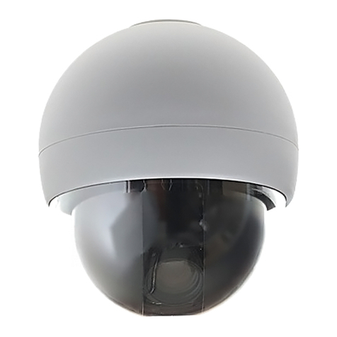
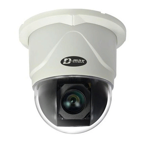
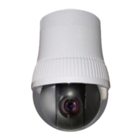
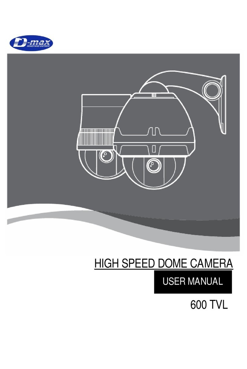
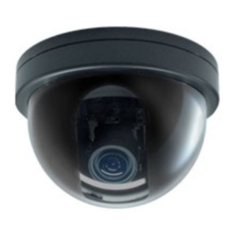
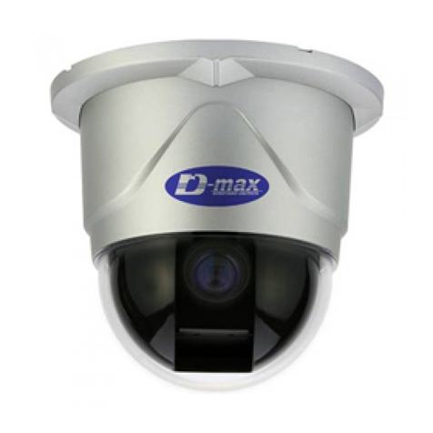
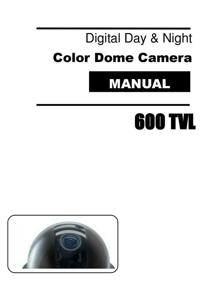
D-MAX DSC-230SI User manual

SUPERIOR SPEED DOME
USER MANUAL
DSC-230SI


S U P E R I O R S P E E D D O M E
INSTALLATION/OPERATION/PROGRAMMING MANUAL
22X Day / Night Speed Dome Camera

3
WARNING
Always have the unit installed by the store it was purchased from.
zImproper connections and/or installation could result in electrical shock, fire or other
serious injury or damage.
Do not place the unit on an unstable surface.
zAlways checks the strength and stability of the installation location.
zA falling unit will result in damage and could cause serious injury.
Never disassemble or attempt to repair or modify the unit.
zDisassemble by untrained personnel could result in serious electrical shock, fire and/or
malfunction.
Never use in locations where combustible materials are used.
zThe unit should never be used where combustible materials, such as gases, are being
used.
zFire, explosion or other serious accidents could occur
Never touch electrical connections with wet hands.
zTouching electrical connections with wet hands could result in serious electrical shock.
Never expose the unit to water.
zIf the unit becomes wet, turn off the power and unplug it immediately.
zStop using the unit if it becomes wet and contact your nearest supplier or manufacturer
representative.
Never use the unit if there is an abnormality.
zTurn off the power and unplug the unit immediately if there is any type of abnormality,
such as a strange smell or smoke.
zContinuing to use a unit that is not operation properly could result in serious injury or
damage to the unit.
Always use the designated power supply.
zFailure to use the proper power supply could result in fire, electrical shock, serious injury
and/or damage.
zAlways uses the designated power supply.
Always handle the connecting cords properly.
zNever damage or modify the connecting cords.
zNever pull on the connecting cord, expose them to extreme heat and/or place heavy
objects on top of them.
zFailure to follow these warnings could result in fire, electrical shock or other damage or
injury.

4
CAUTION
Always use the unit indoors.
zThe unit should never be used outdoors, or in any place where it will be exposed to rain
or other extremes of moisture.
zDirect exposure to water will result in rust and will damage the unit.
Never use in environments that have heavy concentrations of dust, smoke, steam or
humidity.
zEnvironments such as these could result in fire, electrical shock or other serious damage
or injury.
Never place the unit in extremes of high or low temperatures.
zExtreme temperatures will damage the unit.
zAlways use within an operating range of -10℃to 50℃(14℉~ 122℉) for indoor speed
dome camera.
Never place the unit near the magnetic.
zThe unit should never be placed near by magnetic.
zIt is reason for the malfunctions.
Never expose the unit to impact.
zStrong impact may seriously damage the unit.
FOR PROPER OPERATION
Never install the unit yourself.
zThe unit should be installed by trained personnel.
This product has been designed and manufactured in accordance with the harmonized European standards,
following the provisions of the below stated directives.
Electromagnetic Compatibility Directive 89/336/EEC(EN60065:1998, EN61000-6-3:2001, EN61000-6-1:1997)
This devise complies with part 15 of the fcc rules operation is subject to the following two conditions: (1) This
device may not cause harmful interference and (2) This device must accept any interference received including
interference that may cause undesired operation

5
1. WELCOME 6
2. INTRODUCTION OF PRODUCT 7
2.1 PRODUCT FEATURES 7
3. INSTALLING AND CONNECTING WITH EQUIPMENTS 8
3.1 NAME AND FUNCTION OF EACH PART 8
3.1.1 THE NAME OF EACH PART 8
3.1.2 INSTALLATION AND WIRING 9
3.2 CONNECTING WITH EQUIPMENTS 12
3.2.1 BASIC CONNECTION DIAGRAMS 12
3.2.2 CONNECTION DIAGRAMS IN DETAIL 13
4. HOW TO USE FUNCTIONAL DIP SWITCHES 14
4.1. SETTING DIP SWITCHES 14
4.1.1 SETTING OPTIONAL DIP SWITCHES 14
4.1.2 SETTING ADDRESS DIP SWITCHES 16
4.1.3
SETTING BAUD RATE WITH DIP SWITCHES 17
4.1.4
SETTING PROTOCOLS WITH DIP SWITCHES 18
5. HOW TO OPERATE YOUR DOME SYSTEM 19
5.1 HOW TO OPERATE YOUR DOME SYSTEM 19
5.2 ACCESSING OSD MENU 20
6. HOW TO PROGRAM YOUR DOME SYSTEM 21
7. DOME SETTING 22
8. PRESET PROGRAMMING 33
9. SWING PROGRAMMING 34
10. GROUP PROGRAMMING 35
11. TOUR PROGRAMMING 36
12. SPIRAL PROGRAMMING 37
13. PTZ TRACE 38
14. ERROR MESSAGES 39
15. TROUBLE SHOOTING 40
16. DIMENSIONS 41
17. SPECIFICATIONS 42
18. QUICK STARTING – OSD MENU TREE 43
TABLE OF CONTENTS

6
Getting Started
1. WELCOME
Thank you for purchasing the integrated speed dome system, Superior Speed
Dome. Your new system features a high-resolution, color camera/optics package with
Day/Night, DSS technology and programmable dome drive software with OSD menu.
This manual is designed to be a reference tool for the installation, operation and
programming of your system. Inside you will find information about Superior Speed
Dome’s features and commands in detailed menu tree.
You will need to install your dome system before using this manual. Refer to the
installation section in this manual for installation instruction.
Once installed apply power to the high speed dome system. The system will start an
initializing sequesnce. When initializing is done, the following information is displayed :
Speed Dome Camera
Memory checking
Address : XXX SP : 90
Please Wait ! ...
This information will display for a second after initializing.
Refer to the following pages to learn how to install, operate and program your dome
system.

7
2.1 Product Features
☺22x Zoom lens
22x optical zoom lens combined with an auto focus
system and digital zoom enables you to get
maximum 220x great pictures.
☺A low light function
Surveillance with optimum picture is possible owing
to digital-slow-shutter function and backlight
compensation function.
zDigital-slow-shutter function is improving the CCD
sensitivity by electrically lengthening exposure time
so that it should be under surveillance on the
condition of 0.01 Lux in color.
☺Various auto-surveillance functions
zPTZ trace
Realizes the registered manual operation for about
120 seconds.
zAuto swing
Repeat pan and tilt between two preset positions.
zGroup sequence
Switches and checks a maximum of 64 preset
positions in order.
zTour sequence
Switches and checks a maximum of 6 group
sequences in order.
☺128 Preset position
A maximum of 128 preset positions can be
programmable. The preset function enables to set
where you want on monitor at any time.
☺Smart pan/tilt function
zIt should be rotated pan travel by 360° endless.
zPan and tilt speed compensation function in
proportion to depth of zoom.
☺Day & Night function with filter
zIt allows make surveillance in the night or low
illumination condition with electronic sensitivity
system. (0.1 Lux)
zIn the darkness, it should be changed to black &
white mode automatically.
☺4ch alarm inputs
It can be directly connected sensor and used with
presets owing to built-in 4-channel sensor input
terminals. It can be also operated together other
equipment owing to built-in alarm output.
(1-Relay normal output)
☺Auto flip function
The unit can be track the moving object
automatically until 180° in vertical by using controller.
☺6 Privacy Zones
For the privacy, it can be programmed masking zone
up to 6 locations on the OSD menu screen.
☺OSD (On Screen Display) Menu
Provides character information displayed on the
monitor, such as the camera ID address, camera
name, preset number, sequence status, and sets
various functions of camera easily on the OSD menu
screen.
2. INTRODUCTION OF THE PRODUCT
8
3.1 Name and Function of each part
3.1.1 The name of each part
;
Figure 1. INDOOR SPEED DOME
3. INSTALLING AND CONNECTING WITH EQUIPMENT
A- BACK BOX
There is a dome drive in it,
connect power cable, data
cables and video cable and
sensors into it.
B- DOME DRIVE
It is a dome drive. All control
equipments and camera are
inside.
C- LOWER BUBBLE
Insert the dome drive into the
back box, then close to lower
bubble finally.

9
3.1.2 Installation and wiring
(1) Disassembly the camera for installation
Figure 2. Disassembly the dome
First, loose the dome drive from the
back box.
zLoose first, the dome drive from the
back box.
zLoose the bolt on the side of cover
with a screw driver and it could be
removed lower bubble in a way that
turn left to lower bubble softly with
both hands then pull out it.
zRemove the dome drive from back
box.
zThere are 3 bolts on the dome
drive. They should not be full
pulled out to prevent missing.
zLoose three of round-headed
bolts from the dome drive. It can
be out up to about 1cm to prevent
missing after loosen all.
zLoose the all of bolts and then
pull up the lip of dome drive with
both hands.
zRemove the dome drive from back
box.

10
(2) Inside of the back box for installation
Figure 3.
zPlease be careful while connecting as shown below.
Figure 4. WIRING PART OF THE BACK BOX
If you unscrew one of
bolt (with ‘+’ screw
driver) on the connector
cover, it is opened Open the connector cover.
Please connect Data,
Power and Video cables.
zPlug in one end of (-) RS-485 data cable.
zPlug in one end of (+) RS-485 data cable.
zPlug in one end of output (24Vac) from
the power supply.
zPlug in one end of video signal cable.

11
zDid you connect the power cable in normal?
Figure 5.
INPORTANT NOTICE BEFORE INSTALLATION
zNever extend the secondary cable of a power supply that is supplied in the pack. If it is extended the secondary cable, cause
serious damage to power unit of the dome.
zNever use UTP cable for power cable and please use solid or stranded wires.
zIf do not use a supplied power supply in the pack, please refer to as following recommended wiring distance chart.
Product Capacity Chart
A partial list of compatible products and the number of units that may be powered by each power supply are listed below. Capacity is
based on the VA rating of each product to be used with the power supply.
Product The capacity of applied power supply
36 W 144 W 288 W
Superior Speed Dome (24 VAC) 1 Dome 4 Domes 8 Domes
The following are the recommended maximum distances (transformer to load) and are calculated with 10-percent voltage drop. (Ten
percent is generally the maximum allowable voltage drop for AC powered devices.) Distances are calculated in meter; values in
parentheses are feet.
Recommended Wiring Distance Chart
Wire Gauge
Input
Voltage Input Current Q’ty of
Camera 18 AWG (1.0㎟) 16 AWG (1.5㎟)
24 VAC 1.5 A 1 45 m (150 ft) 72 m (238 ft)
24 VAC 3 A 2 19 m (64 ft) 31 m (102 ft)
28 VAC 1.5 A 1 62 m (204 ft) 99 m (325 ft)
zIf yes, 1) the power is
on, RED LED glows
which is in the
middle of connector.
z2) The input power source
is AC 24V with a terminal
and with a jack.
zBoth of them can be used.

12
OUTPUT
R
Y
O
UT
R
Y
O
UT
ALARM C
H1
C
H2
C
H4
C
H3
C
OC
OAC24V
48
5-
(4
22
-
48
5+
(4
22
+
IN)
42
2+
O
UT
42
2+
O
UT
G
N INPUT
INPUT
SENSOR DATA INPUT
AC24V
INPUT
RS-485/RS-422 DATA
TWIST PAIR SHIELD CABLE
3.2 Connecting with equipments
3.2.1 Basic connection diagrams
zUsing dedicated keyboard controller, it controls and connects a max. 255 of cameras. In the data box of
controller, there are two controlling terminal ports and it allows the each terminal port to connect with 128
cameras totally.
zIf it is used the twist paired shield cable (AWG23), allows connect up to distance of max. 1.2 Km. According to
the condition of place, it is only whether to be long or to be short.
zFirstly, it would be arranged the following:
-1 PC of power adaptor using of AC 24V / 1.5A for speed dome camera.
-1 PC of power adaptor using of DC 9V / 500 mA for keyboard controller.
-Wired cables from monitor to camera for video signals.
-Wired cables from keyboard controller to camera for data signals.
zConnect video cable from video output terminal in the back box to the video input terminal of monitor.
zConnect AC 24V / 1.5 A of the power supply from power input terminal in the back box to the power source.
Figure 6. CONNECTING WITH EQUIPMENTS
zConnect two pair-cables i.e. (+) and (-) signal of RS-485 terminals to the terminal of data box which is a
subsidiary of keyboard controller through hall of the back box. In wiring, please keep to match to (+) pole and (-)
pole.
zConnect RJ-45 cable of data box to the keyboard controller. To use data box, please use DC 9V / 500mA of
power supply at the same time as it is a power source for a keyboard controller.
zFinally, connect RJ-45 cable of data box to the keyboard. It can supply power to the keyboard.

13
3.2.2 Connection diagrams
Figure 7. CONNECTION DIAGRAM
-Sensor can be connected to a maximum of 4-Channels and if it activates to detect by sensor with PRESET
function, automatically the camera moves to the point by PRESET MODE.
-Alarm output is a relay switching voltage to be load up to AC/DC24V/0.5A and when it is detected by sensor, it is
automatically switching on, can be released through the times or by controller.
-For monitoring BNC video cable must be directly connected to the monitor.
-Data can be process by RS485 or RS422 and it can be used for parallel connection for connecting many
cameras.
-Even if it must be used 2-twist paired cable in use of RS422, the terminal port which it was connected with
RS485 cable port with 1-pair cable when it is not necessary to take a return data from camera.
NOTE: Power source must be used AC 24 V, 1.5 Amp output of electric current and use a Double
Winding Transformer as possible as.

14
4.1 Setting DIP switches
4.1.1 Setting optional DIP switches
- TERMINATION REGISTER (DIP SWITCH No. 1):
This switch allows the end of register to turn on the only last camera of the data lines. If data lines are
distributed to several directions, it has to be switched on such camera among the most far away cameras. It
switched off from factory defaults.
(Refer to part c of the figure 8)
- RS485 / RS422 SELECT (DIP SWITCH No. 2):
Select switch on / off so that the data type is to be proper to your actual using by RS485 or RS422. The
default setting is RS485 mode.
(Refer to part c of the figure 8)
-ADDR / INIT SELECT (DIP SWITCH No. 3):
This switch allows set up the communication baud rate, it sets to be proper data baud rate to be transferred
from controller. In switch off, it is to become 9600 bps and to become 4800 bps in switch on. Power off and
on so that changed speed is applied. The Default setting is 9600 bps.
(Refer to part c of the figure 8)
-NTSC / PAL SELECT (DIP SWITCH No. 4):
As a converting switch NTSC system to PAL system, this switch cannot be changed by user due to the
setting up a fix in the mill. Please do not change. If you want to change the switch, please check model of
this product which is a NTSC or PAL.
(Refer to part c of the figure 8)
-EXT / INT (DIP SWITCH No. 5):
The EXT switch is AC Line-Lock and the INT switch is internal sync. If you want to use the unit in the AC
line-Lock, switch to EXT, the default is EXT
(Refer to part c of the figure 8).
-TURN ON/OFF SWITCH:
To start the speed dome camera, turn on the switch. If in reverse, turn off the switch.
(Refer to part a of the figure 8)
4. HOW TO USE FUNCTIONAL DIP SWITCHES

15
Figure 8. DIP SIWTCH PANNEL ON THE DOME
NOTE: Please you have to set up the DIP switches in turn off the power then finish the set up, turn
on the power.
When you set the DIP switch, please
set the DIP switch condition of power
off firstly then turn on the power. Part A
is a power switch.
This part can be set up the address for
each camera. You can set up the
number of camera on the condition of
ADDR in Part C.
In ‘INIT’ of the part C, you can select
protocols and data communication
baud rate.
Please refer to next page
It is to notice whether power on and
data signal in normal. In power on, the
Green LED is lit and on operating, the
Green LED is lit at the same time the
Red LED is flickered.

16
4.1.2 Setting address of DIP Switches
Use address setting by DIP switches No. 1 to No. 8, It can be set 1 program to 255 programs.
TABLE OF ADDRESS SETTING
DIP SWITCH (HEX) DIP SWITCH (HEX)
RX
NO
(DEC) 1 2 3 4 5 6 7
RX
NO
(DEC) 1 2 3 4 5 6 7
1 ON OFF OFF OFF OFF OFF OFF 33 ON OFF OFF OFF OFF ON OFF
2 OFF ON OFF OFF OFF OFF OFF 34 OFF ON OFF OFF OFF ON OFF
3 ON ON OFF OFF OFF OFF OFF 35 ON ON OFF OFF OFF ON OFF
4 OFF OFF ON OFF OFF OFF OFF 36 OFF OFF ON OFF OFF ON OFF
5 ON OFF ON OFF OFF OFF OFF 37 ON OFF ON OFF OFF ON OFF
6 OFF ON ON OFF OFF OFF OFF 38 OFF ON ON OFF OFF ON OFF
7 ON ON ON OFF OFF OFF OFF 39 ON ON ON OFF OFF ON OFF
8 OFF OFF OFF ON OFF OFF OFF 40 OFF OFF OFF ON OFF ON OFF
9 ON OFF OFF ON OFF OFF OFF 41 ON OFF OFF ON OFF ON OFF
10 OFF ON OFF ON OFF OFF OFF 42 OFF ON OFF ON OFF ON OFF
11 ON ON OFF ON OFF OFF OFF 43 ON ON OFF ON OFF ON OFF
12 OFF OFF ON ON OFF OFF OFF 44 OFF OFF ON ON OFF ON OFF
13 ON OFF ON ON OFF OFF OFF 45 ON OFF ON ON OFF ON OFF
14 OFF ON ON ON OFF OFF OFF 46 OFF ON ON ON OFF ON OFF
15 ON ON ON ON OFF OFF OFF 47 ON ON ON ON OFF ON OFF
16 OFF OFF OFF OFF ON OFF OFF 48 OFF OFF OFF OFF ON ON OFF
17 ON OFF OFF OFF ON OFF OFF 49 ON OFF OFF OFF ON ON OFF
18 OFF ON OFF OFF ON OFF OFF 50 OFF ON OFF OFF ON ON OFF
19 ON ON OFF OFF ON OFF OFF 51 ON ON OFF OFF ON ON OFF
20 OFF OFF ON OFF ON OFF OFF 52 OFF OFF ON OFF ON ON OFF
21 ON OFF ON OFF ON OFF OFF 53 ON OFF ON OFF ON ON OFF
22 OFF ON ON OFF ON OFF OFF 54 OFF ON ON OFF ON ON OFF
23 ON ON ON OFF ON OFF OFF 55 ON ON ON OFF ON ON OFF
24 OFF OFF OFF ON ON OFF OFF 56 OFF OFF OFF ON ON ON OFF
25 ON OFF OFF ON ON OFF OFF 57 ON OFF OFF ON ON ON OFF
26 OFF ON OFF ON ON OFF OFF 58 OFF ON OFF ON ON ON OFF
27 ON ON OFF ON ON OFF OFF 59 ON ON OFF ON ON ON OFF
28 OFF OFF ON ON ON OFF OFF 60 OFF OFF ON ON ON ON OFF
29 ON OFF ON ON ON OFF OFF 61 ON OFF ON ON ON ON OFF
30 OFF ON ON ON ON OFF OFF 62 OFF ON ON ON ON ON OFF
31 ON ON ON ON ON OFF OFF 63 ON ON ON ON ON ON OFF
32 OFF OFF OFF OFF OFF ON OFF 64 OFF OFF OFF OFF OFF OFF ON
*** If No.7 of DIP switch is ON, Rx No.1 changes to Rx No.65 in the above table and in last, Rx No.64 changes to Rx.
No.128.
If No.7 of DIP switch is OFF and ext No.8 of IP switch is ON, then Rx No.1 changes to Rx No.129 in the above table
and if No.7, No.8 of DIP switches are ON, then Rx No.1 changes to Rx 193 so that it can be set up to Max 255 of
address. In the above table, Rx number is same to camera number.

17
4.1.3 Setting baud rate with DIP switches
These DIP switches allow the user to set data communication baud rate according to the desired protocol.
The protocols are selected with 2400 bps, 4800 bps and 9600 bps. Use baud rate for this speed dome with DIP switches as
bellows:
To program the baud rate, the power switch must be turned off in advance and then after setting of DIP switch, it must be
turned on the power.
The following steps should be taken care while setting for 2400 bps:
zTurn off the power on the dome.
zDIP SW (INITADDR) must be switched to ‘INIT’ first.
zDIP SW 7 is ON.
zTurn on the power to initialize 2400 bps.
zTurn off the power after initializing baud rate and switch from ‘INIT’ to ‘ADDR’ and DIP SW 7 is off.
zTurn on the power again. Now it is on 2400 bps.
The following steps should be taken care while setting for 4800 bps:
zTurn off the power on the dome.
zDIP SW (INITADDR) must be switched to ‘INIT’ first.
zDIP SW 8 is on.
zTurn on the power to initialize 4800 bps.
zTurn off the power after initializing baud rate and switch from ‘INIT’ to ‘ADDR’ and DIP SW 8 is off.
zTurn on the power again. Now it is on 4800 bps.
The following steps should be taken care while setting for 9600 bps:
zTurn off the power on the dome.
zDIP SW (INITADDR) must be switched to ‘INIT’ first.
zDIP SW 7 & 8 is off.
zTurn on the power to initialize 9600 bps.
zTurn off the power after initializing baud rate and switch from ‘INIT’ to ‘ADDR’.
zTurn on the power again. Now it is on 9600 bps. (9600 bps is default baud rate from factory.)
BAUD RATE DIP SW
‘INITADDR’ DIP SW 7 DIP SW 8
2400 bps INIT ON OFF
4800 bps INIT OFF ON
9600 bps INIT OFF OFF
1 2 3 4 5 6 7 8
O
N 4
2
2
I
N
I
T
P
A
L
I
N
T
.
ON
OFF
A D D R E S S
T
M 4
8
5
A
D
D
R
N
T
S
C
E
X
T
.
ON
O
F
F

18
4.1.4 Setting protocols with DIP switches
It allows user to operate this dome with various command protocols. It can be selected with DIP switches.
To set up the protocol, the power switch must be turned off in advance.
The following steps are the setting protocol:
zTurn off the power on the dome.
zDIP SW (INITADDR) must be switched to ‘INIT’ first.
zSwitch on the each DIP SW as desire.
zTurn on the power to initialize for the protocol.
zTurn off the power after initializing the protocol and all DIP SW that switched on for programming protocol is switched
off again. (DIP SW ‘INIT’ is switched to ‘ADDR’ also.)
zSet address switches as desire.
zTurn on the power again.
zNow it can be operated on desired protocol.
zThe default is D-MAX protocol, 9600 bps.
PROTOCOL DIP SW
‘INITADDR’ DIP SW 1 DIP SW 2 DIP SW 7 DIP SW 8
D-MAX (9600 bps) INIT OFF OFF OFF OFF
P-P (9600 bps) INIT ON OFF OFF OFF
P-P (4800 bps) INIT ON OFF OFF ON
P-P (2400 bps) INIT ON OFF ON OFF
P-D (4800 bps) INIT OFF ON OFF ON
P-D (2400 bps) INIT OFF ON ON OFF
AD (RS-422) INIT ON ON OFF ON
1 2 3 4 5 6 7 8
O
N 42
2
I
N
I
T
P
A
L
I
N
T
.
ON
OFF
A D D R E S S
T
M 48
5
A
D
D
R
N
T
S
C
E
X
T
.
ON
O
F
F

19
5.1 How to operate your dome system
* Digital zoom magnifies the image electronically and the picture may appear pixilated. The larger the digital zoom
limit the greater the reduction in resolution.
5. HOW TO OPERATE YOUR DOME SYSTEM
How to Control
Move joystick or press the direction keys left/right (PAN) and up/down (TILT).
To zoom out, do the following:
1. Press the Zoom In button or turn the joystick clockwise until zoom stops at the
44X zoom limit.
2. Release the button or joystick for one second.
3. To continue zooming (digitally), press the button or turn the joystick clockwise
again until you have the picture you want or reach the digital zoom* limit.
Press the Zoom-In button or turn the joystick counterclockwise.
[SET] + [SWING]
[SET] + [SWING]
Refer to the preset programming section in this manual as well as with the
keyboard’s manual.
Refer to the group programming section in this manual as well as with the
keyboard’s manual.
Refer to the tour programming section in this manual as well as with the keyboard’s
manual.
Refer to the privacy masking zone section as well as with the keyboard’s manual.
Refer to the alarms section in this manual as well as with the keyboard’s manual.
Refer to the Alarms section in this manual.
Turn on or off in the programming ODS menu. Refer to the Auto Tilt Move section
in this manual.
Operation
Pan and Tilt
Zoom Out
Zoom In
Swing
Pan Swing
Tilt Swing
Presets
Group Tour
Auto Tour
PTZ Trace
Privacy masking
Zones
Alarms
Auto Tilt Move
Table of contents
Other D-MAX Security Camera manuals

D-MAX
D-MAX DCC-500DV User manual

D-MAX
D-MAX DSC-737SE User manual

D-MAX
D-MAX 600 TVL User manual

D-MAX
D-MAX 680 TVL User manual

D-MAX
D-MAX DMC-20SEC User manual

D-MAX
D-MAX DCC-500F User manual

D-MAX
D-MAX 650 TVL User manual

D-MAX
D-MAX DSC-2000Si User manual

D-MAX
D-MAX DCC-520D series User manual

D-MAX
D-MAX DMS-200 User manual

D-MAX
D-MAX Pixim Seawolf DSP User manual

D-MAX
D-MAX DMS-200 User manual

D-MAX
D-MAX DIC-7030DV User manual

D-MAX
D-MAX DCC-500D User manual

D-MAX
D-MAX DWC-548DV User manual

D-MAX
D-MAX DCC-580D Series User manual

D-MAX
D-MAX DMC Series User manual

D-MAX
D-MAX DCC 600d Series User manual

D-MAX
D-MAX DCC-500D User manual

D-MAX
D-MAX DCC-501DV User manual