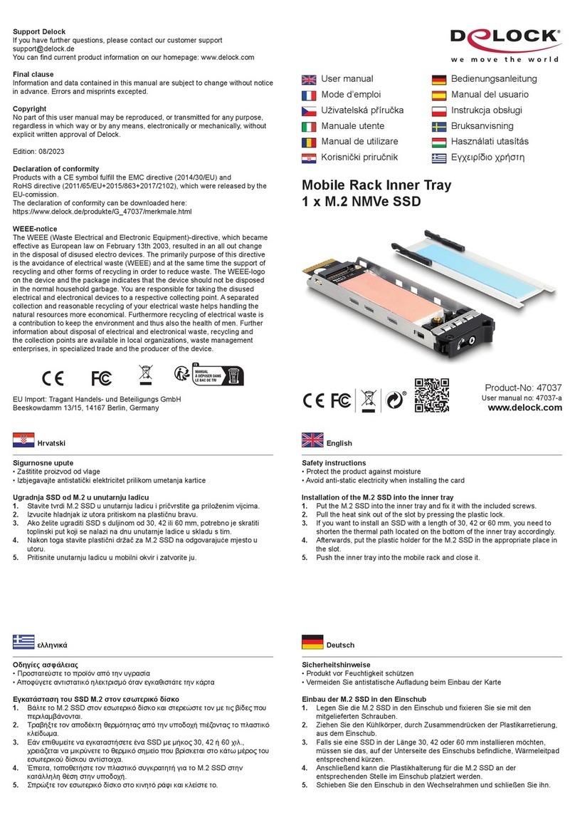
DeLOCK 90406 User manual

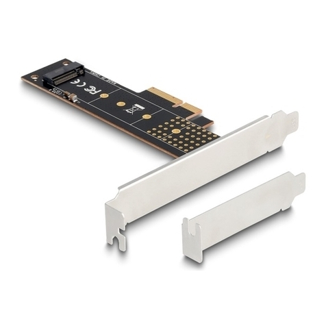
SATA PCI Express x2 Card
2 x SATA 6 Gb/s
Product-No: 90406
User manual no: 90406-a
www.delock.com
User manual
Mode d’emploi
Uživatelská příručka
Manuale utente
Manual de utilizare
Korisnički priručnik
Bedienungsanleitung
Manual del usuario
Instrukcja obsługi
Bruksanvisning
Használati utasítás
Εγχειρίδιο χρήστη

-2-
English
Description
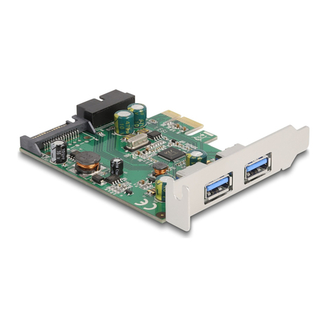
This PCI Express card by Delock expands the PC by two internal SATA ports.
Dierent devices such as SSDs, hard drives, DVD-drives etc. can be connected
to the card.
RAID 1
The special feature of this PCIe card is that an SSD / HDD, which already
contains data, does not need to be formatted in order to build a RAID 1 group
with a second SSD / HDD. The data of the existing SSD / HDD will be mirrored to
a new one.
Specication
• Connectors:
2 x SATA 6 Gb/s 7 pin plug
1 x PCI Express x2, V2.0
4 x 2 pin pin header for LED
• Chipset: Asmedia ASM1062R
• Supports RAID 1
• Jumper for RAID mode ON / OFF
• Supports Native Command Queuing (NCQ)
• Supports S.M.A.R.T.
• Supports TRIM
• Supports DevSleep
• Hot Plug
System requirements
• Linux Kernel 3.3 or above
• Windows 7/7-64/8.1/8.1-64/10/10-64/11
• PC with one free PCI Express x4 / x8 / x16 / x32 slot
Package content
• PCI Express card
• Low prole bracket
• Driver CD
• User manual
Safety instructions
• Protect the product against moisture
• Avoid anti-static electricity when installing the card

-3-
English
Hardware Installation
1. Turn o your PC and unplug the power cord.
2. Open the housing.
3. Remove the slot holder from the available PCI Express slot.
4. Insert the card straight and carefully into the free PCI Express slot, until it is
well seated.
5. Use a screw to attach the card to the housing.
6. Optionally, you can connect LEDs to the pin header.
7. Reattach the housing and connect the power cord to the AC adapter.
LED connector
1. The two LED pin header "P0LED" and "P1LED" are used to connect LEDs,
which indicate the status of the HDD / SSD.
2. The two LED pin header "ERR" are used to connect LEDs, which display the
error message.
Status LED indicator
normal o
error ashing
rebuilding light
RAID setting
Please note:
If you install and activate a Raid system, make sure you have a full back up of
your present data.
Setup a RAID 1 set with existing data on a HDD / SSD. The HDD / SSD with
existing data needs to be connected to "P0 Primary", the second HDD / SSD
needs to be connected to "P1 2nd". Existing data on second HDD / SSD (P1) will
be lost during the process.

-4-
English
BIOS
1. Set jumper J1 to position ON.
2. Turn on the computer, the BIOS on the controller card is executed.
3. Press Ctrl-R to enter into BIOS menu.
4. Choose "Select Congure Controller" in the Main menu. Conrm with "enter".
5. Choose "Create RAID1".
6. Now type "Y" to conrm or "N" to cancel and conrm the entry with "enter".
Then the conguration is started.
7. After completion, the message "Mode Change is completed" appears.
8. Press "Esc" to exit.
9. Set jumper J1 to position OFF.
Windows
1. Set jumper J1 to position ON.
2. Put the driver CD in the CD ROM drive.
3. Open Windows Explorer, select: CD-drive\SATA6G\ASM 1062R\GUI\
RaidManager_V3.130\RaidManagerTool.exe.
4. Choose the drive and select RAID 1.
5. Then click on "execute". After that the RAID will be set up.
6. Shut down the PC.
7. Set jumper J1 to position OFF.
Support Delock
If you have further questions, please contact our customer support
You can nd current product information on our homepage: www.delock.com
Final clause
Information and data contained in this manual are subject to change without
notice in advance. Errors and misprints excepted.
Copyright
No part of this user manual may be reproduced, or transmitted for any purpose,
regardless in which way or by any means, electronically or mechanically, without
explicit written approval of Delock.
Edition: 09/2023

-5-
Deutsch
Kurzbeschreibung
Die PCI Express Karte von Delock erweitert den PC um zwei interne SATA Ports.
An dieser Karte können verschiedene Geräte wie z. B. SSDs, Festplatten, DVD-
Laufwerke etc. angeschlossen werden.
RAID 1
Das Besondere an dieser PCIe Karte ist, dass eine SSD / HDD, welche bereits
Daten enthält, nicht formatiert werden muss, um in einen RAID 1 Verbund
mit einer zweiten SSD / HDD versetzt zu werden. Es werden die Daten der
bestehenden SSD / HDD auf eine neue gespiegelt.
Spezikation
• Anschlüsse:
2 x SATA 6 Gb/s 7 Pin Stecker
1 x PCI Express x2, V2.0
4 x 2 Pin Pfostenstecker für LED
• Chipsatz: Asmedia ASM1062R
• Unterstützt RAID 1
• Jumper für RAID Modus ON / OFF
• Unterstützt Native Command Queuing (NCQ)
• Unterstützt S.M.A.R.T.
• Unterstützt TRIM
• Unterstützt DevSleep
• Hot Plug
Systemvoraussetzungen
• Linux Kernel 3.3 oder höher
• Windows 7/7-64/8.1/8.1-64/10/10-64/11
• PC mit einem freien PCI Express x4 / x8 / x16 / x32 Steckplatz
Packungsinhalt
• PCI Express Karte
• Low Prole Blende
• Treiber CD
• Bedienungsanleitung
Sicherheitshinweise
• Produkt vor Feuchtigkeit schützen
• Vermeiden Sie antistatische Auadung beim Einbau der Karte

-6-
Deutsch
Hardwareinstallation
1. Schalten Sie Ihren PC aus, ziehen Sie das Netzkabel.
2. Önen Sie das Gehäuse.
3. Entfernen Sie das Slotblech vom gewünschten freien PCI Express
Steckplatz.
4. Stecken Sie die Karte gerade und vorsichtig in den freien PCI Express Slot,
bis sie fest sitzt.
5. Befestigen Sie die Karte mit einer Schraube am Gehäuse.
6. Optional können Sie an die Pfostenstecker LEDs anschließen.
7. Schließen Sie das Gehäuse wieder und verbinden Sie das Netzkabel mit
dem Netzteil.
LED Anschluss
1. Die beiden LED Pin Header "P0LED" und "P1LED" dienen dem Anschluss
von LEDs, welche den Status der HDD / SSD anzeigen
2. Die beiden LED Pin Header "ERR" dienen dem Anschluss von LEDs, welche
die Fehlermeldung anzeigen.
Status LED Anzeige
normal aus
Fehler blinkt
Rebuilding leuchtet
RAID Einstellung
Bitte beachten Sie:
Wenn Sie ein Raid System installieren und aktivieren, stellen Sie sicher, dass Sie
ein vollständiges Backup Ihrer vorhandenen Daten haben.
Einstellen einer RAID 1 Konguration mit vorhandenen Daten auf einer HDD
/ SSD. Die HDD / SSD mit den vorhandenen Daten muss an "P0 Primary"
angeschlossen werden, die zweite HDD / SSD an "P1 2nd". Evtl. vorhandene
Daten auf der zweiten HDD / SSD (P1) gehen während des Vorgangs verloren.

-7-
Deutsch
BIOS
1. Setzen Sie den Jumper J1 auf die Position ON.
2. Schalten Sie den Computer ein. Auf der Controller-Karte wird BIOS
ausgeführt.
3. Drücken Sie Strg+R, um das BIOS-Menü aufzurufen.
4. Wählen Sie im Hauptmenü "Select Congure Controller". Bestätigen Sie mit
"Enter".
5. Wählen Sie "Create RAID1".
6. Geben Sie nun "Y" ein zum bestätigen oder "N" um abzubrechen und
bestätigen Sie die Eingabe mit "Enter". Daraufhin wird die Konguration
gestartet.
7. Nach der Fertigstellung erscheint die Meldung "Mode Change is completed".
8. Drücken Sie zum Beenden "Esc".
9. Setzen Sie den Jumper J1 auf die Position OFF.
Windows
1. Setzen Sie den Jumper J1 auf die Position ON.
2. Legen Sie die Treiber CD in Ihr Laufwerk ein.
3. Önen Sie mit dem Explorer folgendes Programm: CD-Laufwerk\SATA6G\
ASM 1062R\GUI\ RaidManager_V3.130\RaidManagerTool.exe.
4. Wählen Sie die Laufwerke und die Einstellung RAID 1 aus.
5. Klicken Sie danach auf "execute" (Ausführen). Daraufhin wird das RAID
erstellt.
6. Schalten Sie den PC aus.
7. Setzen Sie den Jumper J1 auf die Position OFF.

-8-
Deutsch
Support Delock
Bei weitergehenden Supportanfragen wenden Sie sich bitte an
Aktuelle Produktinformationen nden Sie auf unserer Homepage: www.delock.de
Schlussbestimmung
Die in diesem Handbuch enthaltenen Angaben und Daten können ohne vorherige
Ankündigung geändert werden. Irrtümer und Druckfehler vorbehalten.
Copyright
Ohne ausdrückliche schriftliche Erlaubnis von Delock darf kein Teil dieser
Bedienungsanleitung für irgendwelche Zwecke vervielfältigt oder übertragen
werden, unabhängig davon, auf welche Art und Weise oder mit welchen Mitteln,
elektronisch oder mechanisch, dies geschieht.
Stand: 09/2023

-9-
Français
Description
Cette carte PCI Express de Delock étend le PC de deux ports SATA internes.
Diérents appareils tels que des SSD, des disques durs, des lecteurs DVD, etc.
peuvent être connectés à la carte.
RAID 1
Le dispositif spécial de cette carte PCIe fait qu’un SSD / HDD, qui contient déjà
des données, n’a pas besoin d’être formaté pour construire un groupe RAID 1
avec un second SSD / HDD. Les données du SSD / HDD seront reétées au
nouveau.
Spécications techniques
• Connecteurs :
2 x SATA 6 Gb/s à 7 broches mâle
1 x PCI Express x2, V2.0
4 x embase 2 broches pour LED
• Chipset : Asmedia ASM1062R
• Prise en charge de RAID 1
• Pontage pour MARCHE / ARRET du mode RAID
• Prise en charge Native Command Queuing (NCQ)
• Prend en charge S.M.A.R.T.
• Prend en charge TRIM
• Prend en charge DevSleep
• Branchement à chaud
Conguration système requise
• Linux Kernel 3.3 ou version ultérieure
• Windows 7/7-64/8.1/8.1-64/10/10-64/11
• PC avec un slot PCI Express x4 / x8 / x16 / x32 libre
Contenu de l’emballage
• PCI Express Carte
• Low prole slot arrière
• CD d’installation des pilotes
• Mode d’emploi
Instructions de sécurité
• Protéger le produit contre l’humidité
• Éviter l’électricité statique lors de l’installation de la carte

-10-
Français
Installation matérielle
1. Eteignez votre PC et débranchez le cordon d'alimentation.
2. Ouvrez le boîtier.
3. Enlevez le cache du slot PCI Express disponible.
4. Insérez la carte tout droit et avec précaution dans le slot PCI Express libre
jusqu'à ce qu'elle soit bien en place.
5. Utilisez une vis pour attacher la carte au boîtier.
6. Facultativement, vous pouvez connecter des LED à l'embase à broches.
7. Remontez le boîtier et branchez le cordon d'alimentation et l'adaptateur AC.
Connecteur LED
1. Les deux têtes à broches de LED "P0LED" et "P1LED" sont utilisées pour
connecter les LED qui indiquent le statut du HDD / SDD.
2. Les deux têtes à broches de LED "ERR" sont utilisées pour connecter les
LED qui achent le message d’erreur.
Statut Indicateur LED
normal arrêt
erreur clignotant
reconstruction allumé
Conguration RAID
Veuillez noter :
Si vous installez et activez un système Raid, assurez-vous que vous avez une
sauvegarde complète de vos données actuelles.
Conguration d’un RAID 1 avec des données existantes sur un HDD / SDD. Le
HDD / SDD avec des données existantes doit être connecté au "P0 Primary", le
second HDD / SDD doit être connecté au "P1 2nd". Les données existantes sur
le second HDD / SDD (P1) seront perdues pendant le processus.

-11-
Français
BIOS
1. Mettre le pont J1 en position ON (MARCHE).
2. Allumez l'ordinateur, le BIOS de la carte contrôleur est exécuté.
3. Appuyez sur Ctrl-R pour entrer dans le menu BIOS.
4. Choisir "Select Congure Controller" (Sélectionner Congurer le Contrôleur)
dans le menu principal. Conrmer avec "enter".
5. Choisir "Create RAID1".
6. Maintenant, taper "Y" pour conrmer ou "N" pour annuler, et conrmer l’entrée
avec "enter". La conguration commence.
7. Quand elle est terminée, le message "Mode Change is completed" (Mode de
Changement complété) apparaît.
8. Appuyer sur "Esc" pour sortir.
9. Mettre le pont J1 en position OFF (ARRET).
Windows
1. Mettre le pont J1 en position ON (MARCHE).
2. Mettez le CD de pilotes dans le lecteur de CD ROM.
3. Ouvrez l'Explorateur Windows, sélectionnez : CD-drive\SATA6G\ASM
1062R\GUI\ RaidManager_V3.130\RaidManagerTool.exe.
4. Choisir le drive et sélectionner RAID 1.
5. Puis cliquer sur "execute" (Entrer). Après la conguration de RAID.
6. Fermer le PC.
7. Mettre le pont J1 en position OFF (ARRET).

-12-
Français
Assistance Delock
Si vous avez d'autres questions, veuillez contacter notre assistance client :
Vous pouvez trouver les informations sur nos produits actuels sur notre page
d'accueil : www.delock.fr
Clause nale
Les informations et données contenues dans ce manuel sont sujettes à
modications sans préavis. Sont exclues les erreurs et les fautes d'impression.
Copyright
Aucune partie de ce manuel d'utilisation ne peut être reproduite ou transmise,
quel qu'en soit le but, et sous quelque moyen que ce soit, électronique ou
mécanique, sans l'approbation écrite expresse de Delock.
Version : 09/2023

-13-
Español
Descripción
Esta tarjeta PCI Express de Delock expande el equipo en dos ranuras SATA
internos. Se pueden conectar a la tarjeta diferentes dispositivos, como unidades
de estado sólido, unidades de disco duro, unidades de DVD.
RAID 1
La característica especial de esta tarjeta PCIe es que un SSD / HDD, que ya
contiene datos, no necesita ser formateado para construir un grupo RAID 1 con
un segundo SSD / HDD. Los datos del SSD / HDD existente se reejarán en uno
nuevo.
Especicación técnica
• Conectores:
2 x SATA 6 Gb/s de 7 pines macho
1 x PCI Express x2, V2.0
4 x Base de conexiones de 2 pines para LED
• Conjunto de chips: Asmedia ASM1062R
• Soporta RAID 1
• Puente para el modo RAID ON / OFF
• Admite unidades Native Command Queuing (NCQ)
• Compatible con S.M.A.R.T.
• Compatible con TRIM
• Compatible con DevSleep
• Funciones Conexión en caliente
Requisitos del sistema
• Linux Kernel 3.3 o superior
• Windows 7/7-64/8.1/8.1-64/10/10-64/11
• PC con una ranura PCI Express x4 / x8 / x16 / x32 libre
Contenido del paquete
• Tarjeta PCI Express
• Low prole soporte posterior
• Driver en CD
• Manual del usuario
Instrucciones de seguridad
• Proteja el producto contra el polvo
• Evite la electricidad estática cuando instale la tarjeta

-14-
Español
Hardware Instalación
1. Apague su equipo y desconecte el cable de alimentación.
2. Abra la carcasa.
3. Retire el soporte de la ranura de la ranura PCI Express disponible.
4. Inserte la tarjeta en posición recta y con cuidado en la ranura PCI Express
libre hasta que quede correctamente asentada.
5. Utilice un tornillo para jar la tarjeta a la carcasa.
6. Opcionalmente, puede conectar LED a la base de conexiones.
7. Vuelva a colocar la carcasa y conecte el adaptador de CA del cable de
alimentación.
Conector LED
1. Los cabezales de pines de los dos LED "P0LED" y "P1LED" se utilizan para
conectar los LED, que indican el estado del HDD / SSD.
2. Los cabezales de pines de los dos LED "ERR" se utilizan para conectar los
LED, que muestran el mensaje de error.
Estado Indicador LED
normal apagado
error parpadeante
reconstruyendo luz
Conguración RAID
Nota:
Si instala un sistema Raid activo, asegúrese de que tiene una copia de seguridad
completa de todos los datos actuales.
Congure un conjunto RAID 1 con datos existentes en un HDD / SSD. El HDD /
SSD con datos existentes debe estar conectado a "P0 Primary", el segundo HDD
/ SSD debe estar conectado a "P1 2nd". Los datos existentes en el segundo
HDD / SSD (P1) se perderán durante el proceso.

-15-
Español
BIOS
1. Coloque el puente J1 en posición ON (Encendido).
2. Encienda el equipo, se ejecutará el BIOS de la tarjeta del controlador.
3. Presione Ctrl-R para acceder al menú del BIOS.
4. Elija "Select Congure Controller" (Seleccionar Congurar Controlador) en el
menú principal. Conrme con "enter".
5. Elija "Create RAID1".
6. Ahora escriba "Y" para conrmar o "N" para cancelar y conrmar la entrada
con "enter". Entonces se inicia la conguración.
7. Una vez completado, aparece el mensaje "Mode Change is completed"
(Cambio de modo completado).
8. Presione "Esc" para salir.
9. Coloque el puente J1 en posición OFF (Apagado).
Windows
1. Coloque el puente J1 en posición ON (Encendido).
2. Inserte el CD del controlador en la unidad de CD ROM.
3. Abra el Explorador de Windows y seleccione Unidad_de_CD\SATA6G\ASM
1062R\GUI\ RaidManager_V3.130\RaidManagerTool.exe.
4. Elija la unidad y seleccione RAID 1.
5. Luego pulse "execute" (ejecutar). Después de eso se congurará el RAID.
6. Apaga la PC.
7. Coloque el puente J1 en posición OFF (Apagado).

-16-
Español
Soporte técnico Delock
Si tiene alguna pregunta, póngase en contacto con nuestro servicio de atención
al cliente [email protected]
Puede encontrar información actual del producto en nuestra página Web:
www.delock.es
Cláusula nal
La información y los datos contenidos en este manual están sujetos a cambios
sin previo aviso. Exceptuando errores y erratas.
Copyright
Queda prohibida la reproducción o transmisión para cualquier n de parte alguna
de este manual del usuario, independientemente de la forma en que se realice,
ya sea, electrónicamente o mecánicamente, sin el consentimiento escrito de
Delock.
Versión: 09/2023

-17-
České
Popis
Tato PCI Express karta od Delocku rozšiřuje PC o dva interní porty SATA. Ke
kartě mohou být připojena různá zařízení jako jsou např. SSD, hard disky, DVD
jednotky atd.
RAID 1
Speciální funkcí této karty PCIe je, že SSD / HDD, které již obsahuje data, není
třeba formátovat, když chcete vybudovat skupinu RAID 1 s druhým SSD / HDD.
Data na stávajícím SSD / HDD budou zrcadlena na nový.
Specikace
• Konektor:
2 x SATA 6 Gb/s 7 pin samec
1 x PCI Express x2, V2.0
4 x 2 pin konektor pro LED
• Chipset: Asmedia ASM1062R
• Podporuje RAID 1
• Propojka pro režim RAID ZAPNUTÝ / VYPNUTÝ
• Podpora Native Command Queuing (NCQ)
• Podporuje S.M.A.R.T.
• Podporuje TRIM
• Podporuje DevSleep
• Hot Plug
Systémové požadavky
• Linux Kernel 3.3 nebo vyšší
• Windows 7/7-64/8.1/8.1-64/10/10-64/11
• PC s jedním volným PCI Express x4 / x8 / x16 / x32 slotem
Obsah balení
• Karta PCI Express
• Záslepka do slotu
• CD s ovladači
• Uživatelská příručka
Bezpečnostní pokyny
• Chraňte produkt před vlhkostí
• Při instalaci karty se vyvarujte působení antistatické elektřiny

-18-
České
Instalace hardware
1. Vypněte PC a odpojte přívodní šňůru napájení.
2. Otevřte kryt PC.
3. Vyndejte záslepku z volného PCI Express slotu.
4. Vložte kartu opatrně do volného PCI Express slotu až zcela dosedne.
5. Přišroubujte pomocí šroubováku kartu ke skříni.
6. Volitelně můžete připojit LED do pin konektoru.
7. Nasaďte zpět kryt a připojte napájecí šňůru.
Konektor LED
1. Pinové konektory na dvě LED "P0LED" a "P1LED" se používají k připojení
LED, které udávají stav HDD / SSD.
2. Pinový konektor na dvě LED "ERR" se používá k připojení LED, které
zobrazují chybovou zprávu.
Stav Kontrolka LED
normální vypnutá
chyba bliká
přebudování svítí
Nastavení RAID
Upozornění:
Jestliže instalujete a aktivujete RAID systém, ujistěte se, zda máte zálohována
Vaše data.
Nakongurujte sadu RAID 1 se stávajícími daty na HDD / SSD. HDD / SSD se
stávajícími daty je třeba připojit k "P0 Primary", druhý HDD / SSD je třeba připojit
k "P1 2nd". Data přítomná na druhém HDD / SSD (P1) budou při tomto procesu
ztracena.

-19-
České
BIOS
1. Nastavte propojku J1 do polohy ON (ZAPNUTO).
2. Zapněte počítač, naběhne BIOS SATA karty.
3. Stiskněte Ctrl-R pro vstup do menu BIOS.
4. V hlavní nabídce vyberte "Select Congure Controller" (Vybrat ovladač
kongurace). Potvrďte klávesou "Enter".
5. Vyberte "Create RAID1" (Vytvořit RAID1).
6. Teď napište "Y" pro potvrzení nebo "N" pro zrušení a položku potvrďte
tlačítkem "Enter". Pak bude zahájena kongurace.
7. Po skončení se zobrazí zpráva "Mode Change is completed" (Režim změny
je dokončen).
8. Stiskem tlačítka "Esc" můžete odejít.
9. Propojku J1 nastavte do polohy OFF (VYPNUTO).
Windows
1. Nastavte propojku J1 do polohy ON (ZAPNUTO).
2. Vložte CD s ovladači do mechaniky.
3. Spusťte prohlížeč, zvolte: CD-mechanika\SATA6G\ASM 1062R\GUI\
RaidManager_V3.130\RaidManagerTool.exe.
4. Vyberte diskovou jednotku a dále vyberte RAID 1.
5. Pak klikněte na "execute" (vykonat). Poté bude RAID nakongurován.
6. Vypněte PC.
7. Propojku J1 nastavte do polohy OFF (VYPNUTO).

-20-
České
Podpora Delock
S dalšími technickými otázkami můžete kontaktovat naše středisko podpory:
Aktuální informace o produktu můžete nalézt i na našich webových stránkách:
www.delock.cz
Závěrečné upozornění
Informace a data obsažená v této příručce mohou být změněny bez předchozího
upozornění. Za tiskové chyby neručíme.
Copyright
Žádná část této uživatelské příručky nesmí být reprodukována, přenášena ani
pro jakýkoli účel, bez ohledu na to, jakým způsobem nebo jakými prostředky,
elektronicky nebo mechanicky, bez výslovného písemného souhlasu Delock.
verze: 09/2023
Table of contents
Languages:
Other DeLOCK Computer Hardware manuals

DeLOCK
DeLOCK 88029 User manual

DeLOCK
DeLOCK 89567 User manual

DeLOCK
DeLOCK 62853 User manual

DeLOCK
DeLOCK 62866 User manual

DeLOCK
DeLOCK 95265 User manual

DeLOCK
DeLOCK 88027 User manual

DeLOCK
DeLOCK 47189 User manual

DeLOCK
DeLOCK 63962 User manual

DeLOCK
DeLOCK SuperSpeed 89008 User manual
DeLOCK
DeLOCK 88025 User manual
Popular Computer Hardware manuals by other brands

Kingston Technology
Kingston Technology 486/Now! installation guide

E-peas
E-peas AEM20940 quick start guide

CyClone
CyClone 600-2708 PCI Express user manual

Emerson
Emerson MultiFlex CUB-II Installation and operation manual

ekwb
ekwb EK-FB ASUS ROG ZE Monoblock installation manual

Renesas
Renesas Converter Board R0E530650CFK10 user manual