manuals.online logo
Brands
  1. Home
  2. •
  3. Brands
  4. •
  5. DEMA
  6. •
  7. Dispenser
  8. •
  9. DEMA 692T FOAM STATION I User manual

DEMA 692T FOAM STATION I User manual

DEMA MODEL 692T FOAM STATION I
INSTALLATION INSTRUCTION
I-719 Page 1 of 6
Rev. D-31918 12/22/05
1. PARTS CHECKLIST:
ITEM DESCRIPTION QTY.
A. Foam Station Assembly 1
B. #10 Screw & Anchor Kit Set (Total: 4 Screws & 4 Anchors) 1
C. Ceramic Weight 1
D. ¼” ID Tubing & Foot Valve Assembly 1
E. Metering Tip Kit (P/N 61-9K) 1
F. Label Card 1
2. INSTALLATION:
This product is designed only to be used as described in this instruction sheet. Adhere to all warnings and
cautions identified in this document.
WARNING: Installations must conform to all local and national plumbing codes and use
approved backflow prevention and pressure relief devices where required.
ALWAYS DISCONNECT DISPENSER FROM WATER SOURCE WHEN DISPENSER
IS NOT IN USE.
Always read SDS for all chemicals used and follow personal protective guidelines.
A. Mounting and Water Supply:
Locate mounting holes on a permanent vertical wall. Drill all holes into the drywall using a ¼” diameter bit for use with the
included #10 screw and anchor set. (If mounting unit to wood and you do not plan to use the included anchors, drill 1/8”
diameter holes.) Insert the anchors into drilled holes and hammer them into the wall until they are flush with face of wall.
Assemble the #10 screws with a phillip screwdriver into the anchors for the keyhole slots so the screw heads are sticking out
of the wall approximately ½”. Mount the unit by inserting the screw heads through the keyhole slots and tightening the
screws. Secure the unit by inserting screws into the lower 2 holes.
The water inlet is equipped with a female garden hose fitting. The fitting may be removed to permit direct connection to
3/8” NPT pipe. Note: Apply pipe dope, hand tighten, and then turn 1-1/2 times with a wrench. DO NOT OVER
TIGHTEN.
WARNING: Do not use Teflon tape to seal internal plastic threads as the extra thickness of the tape may cause the
plastic to crack. Use non-welding liquid sealant instead.
WARNING: Water supply should not exceed 125 psi and water temperature must not exceed 150°F.
B. Outlet Connection:
Connect the discharge hose to the garden hose fitting. NOTE: Be sure to clamp garden hose onto wall approximately 1
ft. below the unit, (Clamps, screws, & anchors are not supplied.) Attach shut-off valve to the discharge end of the hose.
See Table 1 for hose limitations.
TABLE 1: Outlet Garden Hose Connection
GARDEN HOSE SIZE AND
LENGTH MIN. PRESSURES
WATER AIR
25’ OF ¾” ID 40 PSI 40 PSI
50’ OF ¾” ID 50 PSI 40 PSI
25’ OF ½” ID 60 PSI 40 PSI
DEMA MODEL 692T FOAM STATION I
INSTALLATION INSTRUCTION
I-719 Page 2 of 6
Rev. D-31918 12/22/05
C. Chemical Supply:
WARNING: USE CARE WHEN HANDLING HAZARDOUS CHEMICALS.
Place the chemical container in a convenient location not more than six feet below the Foam Station. (Greater lifts will
reduce injection capabilities). The top of the container should not be above the Foam Station. Cut the vinyl tube to any
convenient length that will allow the tubing to reach the bottom of the container. Drop the tubing end with the strainer into
the chemical container. Push the other tubing end over the chemical inlet barb located on the side of the Foam Station.
3. CHEMICAL ADJUSTMENT:
The chemical feed rate is controlled by metering tips screwed into the barb on the side of the Foam Station. The feed rates can
be changed using different metering tips. To select the proper metering tip size for the desired dilution ratio, refer to Table 2.
TABLE 2
Metering
Tip Color
Injection Rate for Viscosities Shown
1 cps 75 cps 200 cps 500 cps
Oz/Gal Ratio Oz/Gal Ratio Oz/Gal Ratio Oz/Gal Ratio
Clear 0.84 152-1 0.65 197-1 0.45 284-1 0.30 427-1
Purple 1.35 95-1 1.10 116-1 0.90 142-1 0.60 213-1
Yellow 2.40 53-1 2.00 64-1 1.50 85-1 1.10 116-1
Green 4.20 30-1 3.40 38-1 2.65 48-1 2.10 61-1
Pink 5.25 24-1 4.50 28-1 3.45 37-1 2.60 49-1
Turquoise 9.40 14-1 7.25 18-1 5.45 23-1 3.70 35-1
Black 11.75 11-1 8.80 15-1 6.35 20-1 4.20 30-1
Gray 14.50 9-1 10.80 12-1 7.75 17-1 4.75 27-1
Red 18.00 7-1 13.20 10-1 8.30 15-1 5.00 26-1
Blue 20.60 6-1 14.70 9-1 8.65 14.8-1 5.20 25-1
Brown 24.10 5-1 16.15 8-1 9.30 14-1 5.50 23-1
White 27.50 4.7-1 17.80 7-1 9.70 13-1 5.70 22-1
Orange 30.00 4.3-1 18.50 6.9-1 10.10 12.7-1 5.85 21.9-1
Light Blue 32.00 4-1 18.90 6.8-1 10.20 12.5-1 6.00 21-1
Tan 32.50 3.9-1 19.25 6.6-1 10.40 12.3-1 6.25 20.5-1
None 34.25 3.7-1 20.45 6-1 10.60 12-1 6.50 20-1
All induction rates are based on 40 psi water pressure and 40 psi air pressure.
4. OPERATION:
The 692T Foam Station permits the operator to select a chemical to foam (left hand lever), or a clear water rinse (middle lever)
by opening and closing the appropriate valve with its lever. ONLY ONE VALVE SHOULD BE OPEN AT ANY TIME. If
two valves are opened simultaneously, the injector will not draw chemical.
NOTE: When using the spray wand, make sure that the shut-off valve at the end of the hose is in the fully open position in
order to draw chemical product.
To Foam:
First: Open the left hand lever all the way. Water rushing through the foamer will draw up soap and send soapy water
through the hose.
Next: Pull out on the air regulator knob above the air gage. Set the air regulator to 40psi. Open the air valve on the left side of
the 692T. Adjust the air regulator upwards gradually until you obtain the thickness of foam you desire. Push the air regulator
DEMA MODEL 692T FOAM STATION I
INSTALLATION INSTRUCTION
I-719 Page 3 of 6
Rev. D-31918 12/22/05
knob back in to lock the setting in place. This operation must be repeated in the same order each time the 692T is shut down and
restarted (water first then gradually build up air pressure).
TABLE 3: Water Flow & Air Flow Setting
PRESSURE (PSI)
40 50 60 80
WATER FLOW (GPM) 1.4 1.6 1.7 2.1
AIR FLOW (SCFM) 3.5 4.2 4.8 6.1
5. SERVICING:
PROBLEM: SEE SITUATION:
Unit will not draw or stops drawing chemical 1, 2, 3, 5, 6, 10, 11, 12, 13, 15, 16, 17
Poor foam quality 1, 2, 3, 5, 6, 10, 11, 12, 13, 15, 16
Foam surges 1, 2, 3, 4, 5, 6, 8, 9, 10, 11, 12, 13, 15, 16
Foam output is too wet 1, 3, 4, 5, 6, 7, 8, 9, 10, 11, 13, 16
Foam output is too dry 2
Water is flowing into chemical container 12
Foam does not clean adequately 4, 8, 11, 14
POSSIBLE SITUATIONS
Situation Cause Solution
1 Chemical tube not immersed in chemical
or chemical depleted. Immerse tube in chemical or replace.
2 Air pressure is too high for water. Adjust air regulator down.
3 Water pressure is too low. At least 30 psi is required. Increase if possible, or decrease air pressure.
4 Chemical to water ratio is too low. Change metering tip to one that is larger.
5 Foam hose is kinked. Straighten hose.
6 Foam hose is too long or wrong size. See Table 1.
7 Air supply is inadequate. Increase air pressure by regulating up.
8 Detergent is wrong. Use a more effective detergent, and be sure that product is recommended
for foaming.
9 Using an oiler on the airline may
deteriorate the quality of the foam. Use only clean, dry air.
10 Holes or cuts are in chemical inlet tube. Replace the tube.
11 Strainer and/or metering tip are blocked. Remove, clean or replace.
12 Solution check valve is not working. Remove, clean or replace.
13 Air regulator is not working. Remove, clean or replace.
14 Soil has hardened on surface. Reapplication may be necessary. Be sure to rinse foam off before it dries.
15 Rust or build-up is clogging the foamer
aspirator. Disconnect water from unit and remove injector from unit. Visually
inspect. Remove blockage.
16 Water scale or chemical build-up may
have formed in the water jets. Place the chemical tube in descaling acid and completely open the shut-
off valve. Let unit run until the chemical tube is filled with acid, then
close shut-off valve and water supply. Elevate the chemical tubing and
outlet hose until acid has had enough time to descale. Repeat if necessary.
For severe cases, disassemble unit and soak foamer body in descaling
acid.
17 More than one valve is open. Close the rinse valve.
DEMA MODEL 692T FOAM STATION I
INSTALLATION INSTRUCTION
I-719 Page 4 of 6
Rev. D-31918 12/22/05
Return Policy
No merchandise may be returned for credit without DEMA Engineering Company’s written permission. Return Merchandise
Authorization (RMA) number required in advance of return.
Warranty
DEMA products are warranted against defective material and workmanship under normal use and service for one year from the date of
manufacture. This limited warranty does not apply to any products which have a normal life shorter than one year or failure and damage
caused by chemicals, corrosion, improper voltage supply, physical abuse or misapplication. Rubber and synthetic rubber parts such as
“O”-rings, diaphragms, squeeze tubing and gaskets are considered expendable and are not covered under warranty. This warranty is
extended only to the original buyer of DEMA products. If products are altered or repaired without prior approval of DEMA, this
warranty will be void.
Defective units or parts should be returned to the factory with transportation prepaid. If inspection shows them to be defective, they will
be repaired or replaced without charge. F.O.B. factory DEMA assumes no liability for damages. Return merchandise authorization
number to return units for repair or replacement must be granted in advance of return.
DEMA MODEL 692T FOAM STATION I
INSTALLATION INSTRUCTION
I-719 Page 5 of 6
Rev. D-31918 12/22/05
NO. PART NO. DESCRIPTION
1 100-38 Strainer Washer
2 65-10 Swivel Coupling
3 65-14 Swivel Adapter
4 69-8-2 Top Manifold
5 66-153 Pipe Plug & O-Ring Assy.
6 99-8-2 Valve Knob
7 69-2 Adapter
8 30-5-14 O-Ring (EP)
9 58-83-1 Pipe Adapter
10 69-7-1 Bottom Manifold
11 65-18-1 Outlet Fitting
12 93-2 Pressure Gauge
13 25-137-12 ¼” NPT Nipple X 1 ½” Lg.
NO. PART NO. DESCRIPTION
14 16-11 ¼” NPT Ball Valve
15 24-11L Foot Strainer
16 61-107 Ceramic Weight (3/8” ID Tubing)
17 100-12L Vinyl Tubing (3/8” ID X 8 Ft.
Long)
ACCESSORIES
NO. PART NO. DESCRIPTION
18 93-14 ¾”ID X 25’ Lg. Outlet Hose
19 93-18 Plastic Foam Wand
13
12
9
11
14
FOAMER ASSEMBLY
(SHOWN EXPLODED
ON PAGE 6)
2
13
5
6
8
7
6
9
10
8
4
19
15
18
16
5
17
DEMA MODEL 692T FOAM STATION I
INSTALLATION INSTRUCTION
I-719 Page 6 of 6
Rev. D-31918 12/22/05
NO. PART NO. DESCRIPTION
1 29-18-2 5/16 Internal Snap Ring
2 29-17-2 Washer (S.S.) –Air Hose
3 29-7 O-Ring (Viton)
4 29-5P Ball 11/32” Dia.
5 29-16 Nozzle
6 29-11 Diffuser
7 29-15-2 Pin
8 69-3 Adapter
9 29-12 Check Valve Repair Kit
10 25-29V Metering Knob O-Ring (Viton)
11 23-34-3 Check Valve Core
12 23-9-2 Check Valve Spring
13 23-10 Check Valve Ball (9/32” Dia. S.S.
14 23-11V Check Valve O-Ring (Viton)
15 24-59-5 Metering Knob
16 61-9 Metering Tip (Specify Color)
NO. PART NO. DESCRIPTION
17 30-5V-1 O-Ring (Viton)
18 2914 Air Nozzle
19 93-6-2 Air Check Valve Spring
20 26-49P Ball 3/16” (Teflon)
21 90-35V Air Check Valve Spring
22 29-17-3 Washer (S.S.) – Foamer inlet
23 29-18-4 7/16” Internal Snapring
24 93-1 Pressure Regulator
25 29-10 Hi Lo Screw (Req’d)
ACCESSORIES
NO. PART NO. DESCRIPTION
26 61-9K Metering Tip Kit
FOAMER ASSEMBLY BREAKDOWN
22 21
26
24
19
23 20 18
14
16
15
25
11
13 12
9
17
10
4
1
2
8
7
6
5
3

Other DEMA Dispenser manuals

DEMA 801GAP User manual

DEMA

DEMA 801GAP User manual

DEMA 665 Series User manual

DEMA

DEMA 665 Series User manual

DEMA 607DM-BM User manual

DEMA

DEMA 607DM-BM User manual

DEMA Nitro Plus User manual

DEMA

DEMA Nitro Plus User manual

DEMA 607T-MC User manual

DEMA

DEMA 607T-MC User manual

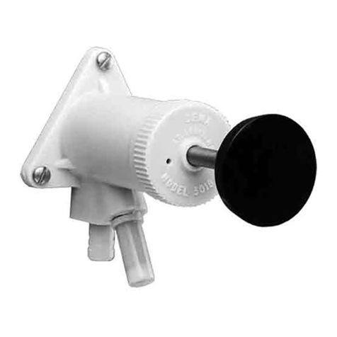
DEMA 301B-SY User manual

DEMA

DEMA 301B-SY User manual

DEMA 652AG User manual

DEMA

DEMA 652AG User manual

DEMA 652GAP User manual

DEMA

DEMA 652GAP User manual

DEMA 651AG User manual

DEMA

DEMA 651AG User manual

DEMA Super Sink Series Assembly instructions

DEMA

DEMA Super Sink Series Assembly instructions

DEMA Olympian O-PDV User manual

DEMA

DEMA Olympian O-PDV User manual

DEMA 651GAP-1 User manual

DEMA

DEMA 651GAP-1 User manual

DEMA 607-3 User manual

DEMA

DEMA 607-3 User manual

DEMA TITAN II User manual

DEMA

DEMA TITAN II User manual

DEMA TITAN II Assembly instructions

DEMA

DEMA TITAN II Assembly instructions

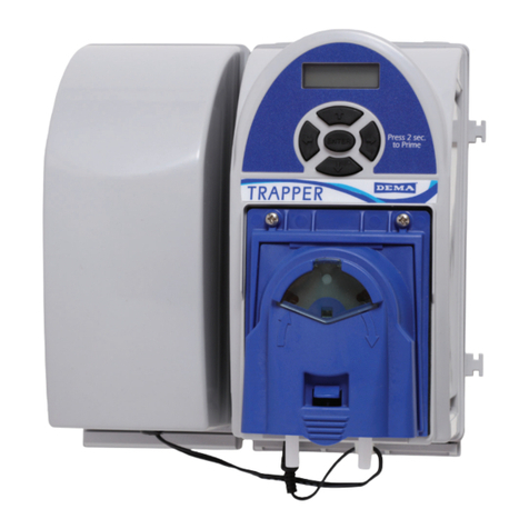
DEMA Trapper User manual

DEMA

DEMA Trapper User manual

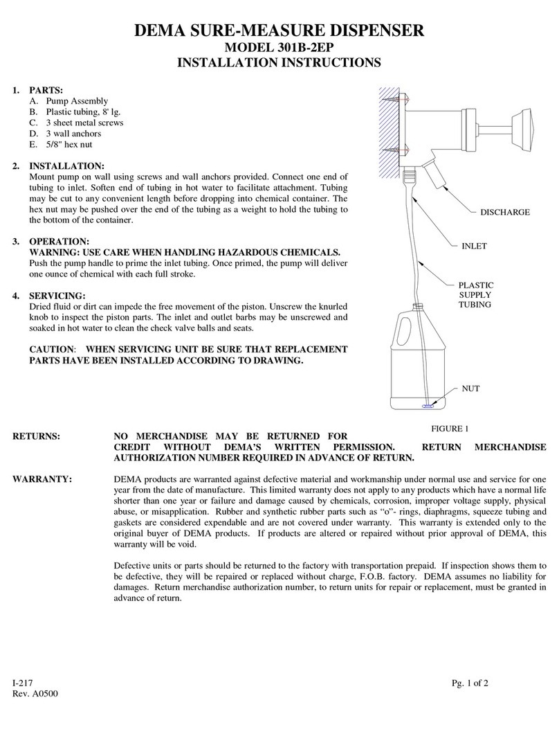
DEMA 301B-2EP User manual

DEMA

DEMA 301B-2EP User manual

DEMA 301B-C User manual

DEMA

DEMA 301B-C User manual

DEMA 302-2 User manual

DEMA

DEMA 302-2 User manual

DEMA Nitro Installation guide

DEMA

DEMA Nitro Installation guide

DEMA 302-1 User manual

DEMA

DEMA 302-1 User manual

DEMA Master Nitro Express User manual

DEMA

DEMA Master Nitro Express User manual

DEMA SQUIRT DC User manual

DEMA

DEMA SQUIRT DC User manual

DEMA SQUIRT DRAIN UNIT User manual

DEMA

DEMA SQUIRT DRAIN UNIT User manual

Popular Dispenser manuals by other brands

Vitlab piccolo 1 operating manual

Vitlab

Vitlab piccolo 1 operating manual

jbc DPM-A instruction manual

jbc

jbc DPM-A instruction manual

Hendi 274125 user manual

Hendi

Hendi 274125 user manual

Salter Brecknell APD-100 User instructions

Salter Brecknell

Salter Brecknell APD-100 User instructions

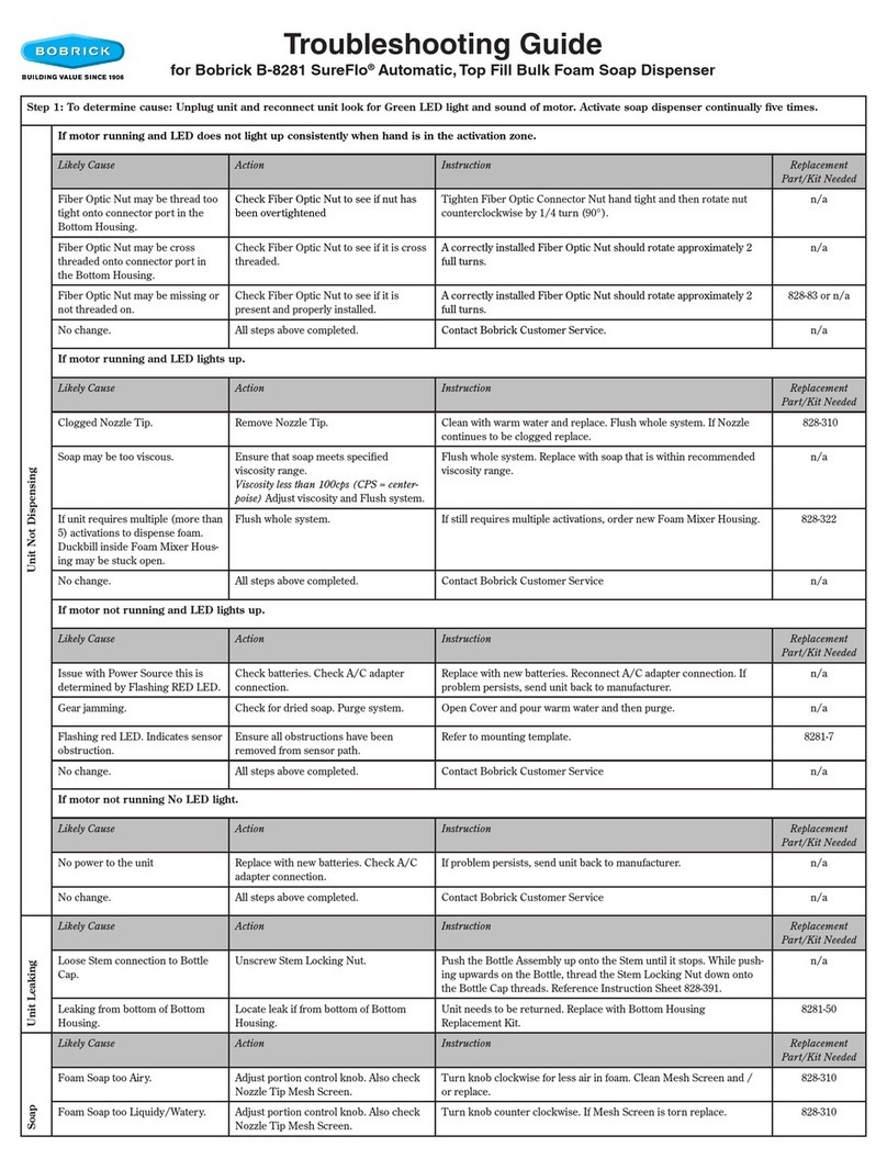
Bobrick SureFlo B-8281 troubleshooting guide

Bobrick

Bobrick SureFlo B-8281 troubleshooting guide

Elkay Smartwell DSSW1808FSC Installation & maintenance

Elkay

Elkay Smartwell DSSW1808FSC Installation & maintenance

SC Johnson Professional Stoko Vario mat Instructions and Mounting Manual

SC Johnson Professional

SC Johnson Professional Stoko Vario mat Instructions and Mounting Manual

Animo CN5e user manual

Animo

Animo CN5e user manual

Bennett CNG Series installation manual

Bennett

Bennett CNG Series installation manual

Franke SD3200 installation guide

Franke

Franke SD3200 installation guide

Displays2go QCRND17PBK quick guide

Displays2go

Displays2go QCRND17PBK quick guide

U-Line H-725 manual

U-Line

U-Line H-725 manual

STRATOS STRX637 Installation and operating instructions

STRATOS

STRATOS STRX637 Installation and operating instructions

Bobrick Designer B-840 troubleshooting guide

Bobrick

Bobrick Designer B-840 troubleshooting guide

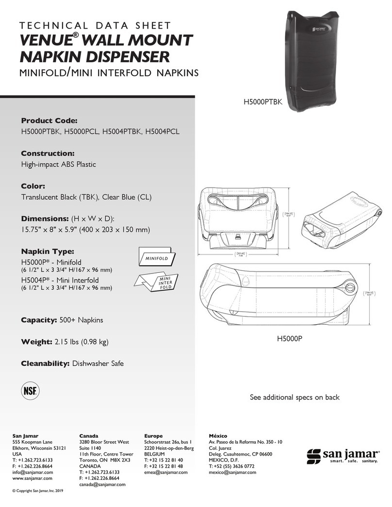
San Jamar VENUE H5000PTBK Technical data sheet

San Jamar

San Jamar VENUE H5000PTBK Technical data sheet

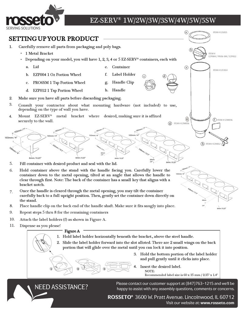
rosseto EZ-SERV 1W quick start guide

rosseto

rosseto EZ-SERV 1W quick start guide

Franke RODX600E Installation and operating instructions

Franke

Franke RODX600E Installation and operating instructions

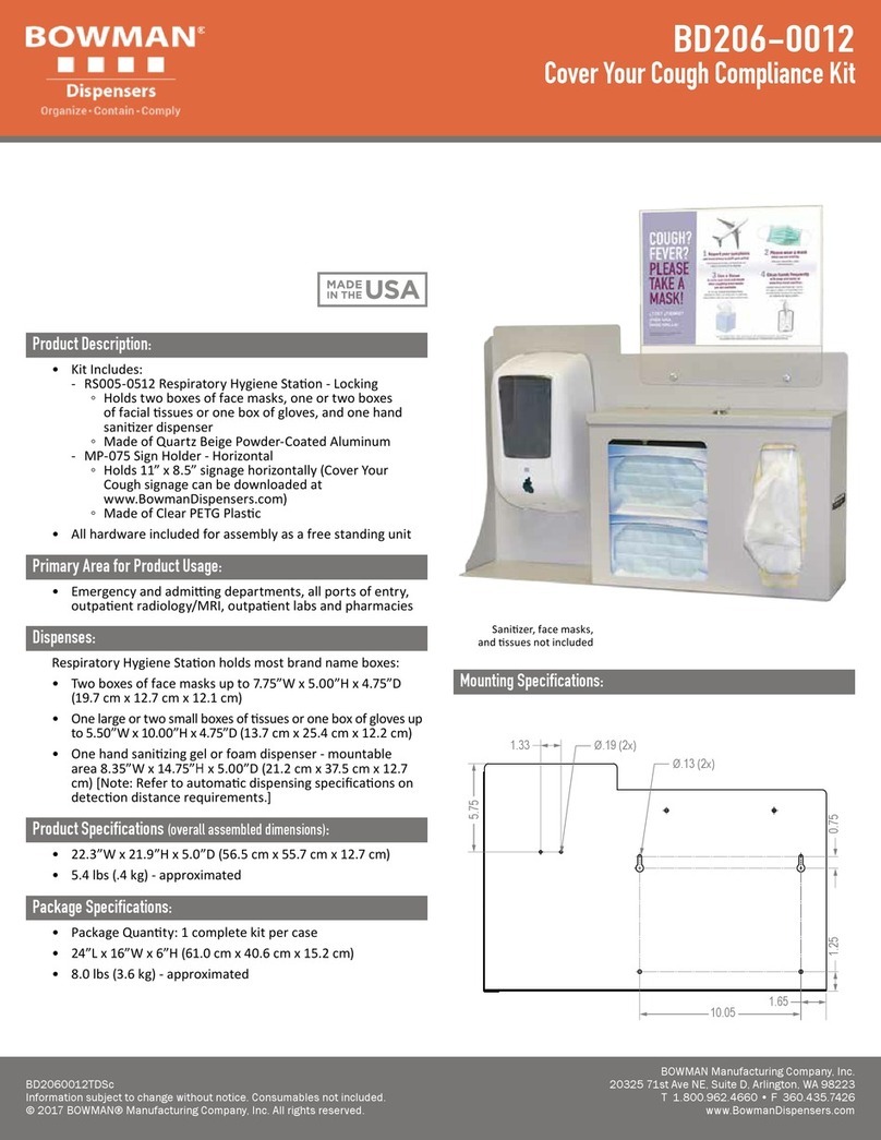
BOWMAN BD206-0012 Assembly instructions

BOWMAN

BOWMAN BD206-0012 Assembly instructions

manuals.online logo
manuals.online logoBrands
  • About & Mission
  • Contact us
  • Privacy Policy
  • Terms and Conditions

Copyright 2025 Manuals.Online. All Rights Reserved.