1 of 2
INS NO. Rev.
08280291 12/08
PAGE
www.dorma-usa.com 1-800-523-8483
"B"
RTS SERIES PACKAGE 04
SIDE LOAD WOOD DOOR AND STEEL FRAME
VALVE "B"
VALVE "A"
"A"
1. PREPARE FRAME AND INSTALL CLOSER
installed prior to frame installation.
NOTE: 8532 mounting channel is to be
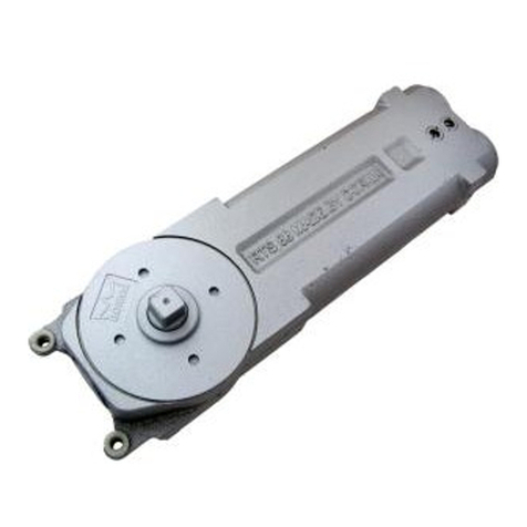
Fasten angle bracket 2 to closer 3
Prepare header 1 according to template.
flat washers. Install two fillister
with two hex head machine screws and
head machine screws 4 into mounting
bearing 16 .
tabs on closer 3 , make approximately
three turns. NOTE: For RTS 88 models
only - do not remove spacer wahsers in
mounting tabs.
Install closer into mounting channel 5
in header 1 by inserting mounting
tabs into mounting bracket. Then raise
end of closer with angle bracket 2
onto the two 1/4-20 screws installed in
mounting channel. Fasten angle bracket
to the remaining 1/4-20 screw with lock
washer and nut 6 . Tighten the two
fillister head machine screws SECURELY!
Install cover plate 7 by sliding tab
into frame and fasten opposite end to
mounting bracket with two No. 8-32
flat head machine screws provided.
2. PREPARE TOP OF DOOR AND INSTALL ARM
Prepare top of door according to template.
NOTE: Cut-out side of door should face
interior of building. Fasten 8832
mounting channel 8 to door with four
No. 12 flat head wood screws 9 .
Install two 1/4-20 hex head alignment
screws 10 into closer arm 11 . Place
closer arm over adjustment stud 12 in
arm channel. Center arm in door, turning
both 1/4-20 hex head alignment screws 10
counterclockwise until they are wedged
against door channel. Thread lateral
adjustment screw 13 into adjustment
stud on 8832 mounting channel 8 .
Secure arm 11 into place with 1/4-20
flat head machine screw and flat
washer 14 .
3. PREPARE BOTTOM OF DOOR, INSTALL ARM AND
FLOOR BEARING
Prepare bottom of door according to
template. Fasten bottom arm 15 to
door with five No. 14 flat head wood
screws. Prepare floor according to
template. Fasten floor bearing 16
with three flat head wood screws and
plastic anchors. SEE TEMPLATE FOR
THRESHOLD PREPARATION.
4. INSTALL DOOR
With door parallel to opening, place
bottom of door onto floor bearing 16 .
Push door to vertical position until
closer spindle is completely engaged
into closer arm 11 . Fasten clamping
block 17 to arm 11 with three
1/4-20 socket head cap screws 18 .
NOTE: Alternate fastening screws when
tightening clamping block. TIGHTEN
SECURELY! Fasten cover plate 19 to
door with screws provided.
5. ADJUST CLOSING SPEEDS
Valve "A" - Controls closing speed
from maximum opening angle to 0°,
clockwise turns decrease closing
speed.
Valve "B" - Increases closing speed from
maximum opening angle to 20°, turn
valve counterclockwise.
6. DOOR ALIGNMENT
Double Acting - Center door in frame by
loosening 1/4-20 flat head screw 14
and adjusting the two 1/4-20 hex head
alignment screws 10 as required.
To adjust clearances between door and
frame, adjust lateral adjustment
screw 13 . Retighten 1/4-20 flat
head screw 14 . TIGHTEN SECURELY!
Single Acting - Adjust arm to insure
that door closes tightly against stop.
Loosen 1/4-20 flat head machine
screw 14 . Adjust closer arm fully
in the direction of door swing. To
adjust clearances between door and
frame, adjust lateral adjustment
screw 13 . Retighten 1/4-20 flat
head machine screw 14 . TIGHTEN
SECURELY!
7. CLEARANCE REQUIREMENTS
The standard spindle for 7471K will
achieve a door clearance of 11/16",
measured from finished floor to bottom
of door. SEE CHART ON TEMPLATE FOR
OPTIONAL SPINDLES AND DOOR CLEARANCES.
8. DOOR REMOVAL
Remove cover plate 19 from side of
door. Remove clamping block 17 from
top arm. Lean top of door out until it
clears frame. Lift door off of floor
INSPK NO. 08280290 Rev.12/08
