3709773 (A3-D-P) 4 / 5
PSS® AirBoss Agile
Self-contained breathing apparatus Instructions for use
4.4.7.7 Adjusting the single cylinder strap
1. Fit the cylinder but do not close the cam lever (see section 4.4.7.1).
2. Move the adjuster buckle (Fig 32, Item 1) so that the stitching is:
– Below the centre bar of the adjuster buckle (A, single cylinder
strap).
– Above the centre bar of the adjuster buckle (B, twin cylinder strap
configured for use with a single cylinder).
3. Close the cam lever, and check that the cylinder is secure.
4. If the cylinder is not secure, release the cam lever and move the
adjuster buckle to adjust cylinder strap tension.
– Move the adjuster buckle toward the cam lever to loosen the strap.
– Move the adjuster buckle away from the cam lever to tighten the
strap.
5. Continue to test and adjust until the cylinder is secure.
4.4.7.8 Adjusting the twin cylinder strap
1. Fit the cylinders but do not close the cam lever (see section 4.4.7.2).
2. Move the adjuster buckle (Fig 33, Item 1) so that the stitching is below
the centre bar of the adjuster buckle.
3. Close the cam lever, and check that the cylinders are secure.
4. If the cylinders are not secure, release the cam lever and move the
adjuster buckle to adjust cylinder strap tension.
– Move the adjuster buckle toward the cam lever to loosen the strap.
– Move the adjuster buckle away from the cam lever to tighten the
strap.
5. Continue to test and adjust until the cylinders are secure.
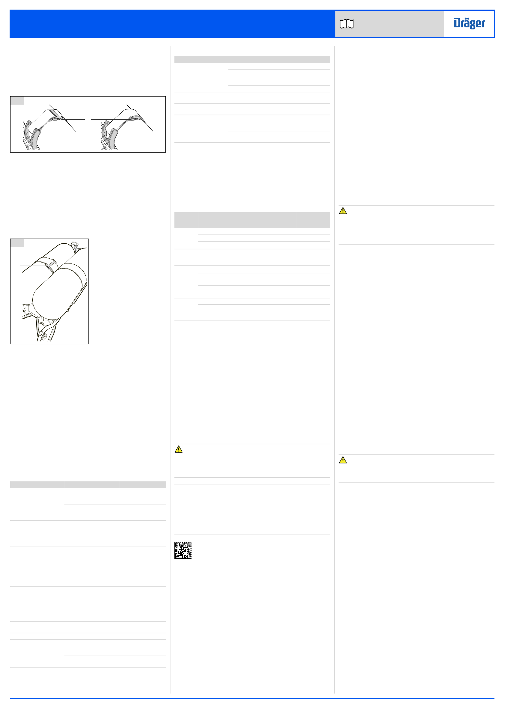
5 Troubleshooting
The troubleshooting guide shows fault diagnosis and repair information
applicable to users of this product. Further troubleshooting and repair
information is available in instructions for use supplied with associated
equipment.
Where the troubleshooting guide shows more than one fault or remedy,
carry out repair actions in the order that they appear in the guide.
Contact trained service personnel or Dräger when the remedy information
indicates a service task, or if the symptom remains after all remedy actions
have been attempted.
5.1 Troubleshooting for breathing apparatus
Symptom Fault Remedy
High-pressure air leak or
failed leak test
Loose of dirty connector Disconnect, clean and
reconnect couplings
and retest
Faulty hose or component Substitute user
replaceable
accessories and retest
Air leak from medium-
pressure hose connector at
the pressure reducer
(pressure relief valve) (see
Fig 2)
Faulty O-ring, retainer,
spring, or pressure reducer
Service task
Air leak from lung demand
valve
Ice particles on sealing
elements
Allow a rush of air to
pass through the valve
by pressing the front
button (Fig 5, Item 2)
then quickly switch off
the positive pressure by
pressing the reset
button (Fig 5, Item 1)
Air leak from cylinder
connector
Ice particles on sealing
elements
Close the cylinder valve
and vent the system.
Disconnect then
reconnect the cylinder.
Pressurize the system
by opening the cylinder
valve slowly, but fully.
Poor sounding whistle Whistle dirty Clean the whistle flute
and retest
Whistle not functioning Activation mechanism fault Service task
Difficulty connecting or
disconnecting the medium-
pressure quick coupling
Dirty connector Disconnect, clean and
reconnect couplings,
and retest
Burring of the male coupling Replace the hose with
the male coupling
A B
32
5305/5469
1
33
5334
1
5.2 Troubleshooting for TX Gauge
6 Maintenance
6.1 Maintenance table
Service and test the product, including out-of-use equipment, in
accordance with the maintenance table. Record all service details and
testing. Refer also to the instructions for use for other associated
equipment.
Additional inspection and testing may be required in the country of use to
ensure compliance with national regulations.
6.2 Cleaning and disinfecting
CAUTION
Trapped water and ice inside the pneumatic system can impair the
operation of the product.
► Prevent any liquid from entering the pneumatic system, and
thoroughly dry the product after cleaning and disinfecting.
NOTICE
Using cleaning and disinfecting methods not described in this section can
damage the equipment.
► Do not exceed 60 °C for drying, and remove components from the
drying facility immediately when dry. Drying time in a heated dryer
must not exceed 30 minutes.
► Do not immerse pneumatic or electronic components in cleaning and
disinfecting solutions or water.
For information about suitable cleaning and disinfecting agents
and their specifications refer to document 9100081 at
www.draeger.com/IFU.
6.2.1 Cleaning and disinfecting the breathing apparatus
Clean the breathing apparatus if it is dirty. If the equipment has been
exposed to contaminants, disinfect any components that come into direct
and prolonged contact with the skin.
Refer also to the instructions for use for the lung demand valve, mask, and
other associated equipment.
Work equipment
– Use only clean lint-free cloths
1. Clean the breathing apparatus manually using a cloth moistened with
cleaning solution to remove excess dirt.
2. Apply disinfecting solution to all internal and external surfaces.
3. Rinse all components thoroughly with clean water to remove all
cleaning and disinfecting agents.
4. Dry all components using a dry cloth, in a heated dryer, or in air.
5. Contact service personnel or Dräger if disassembly of pneumatic or
electronic components is required.
Symptom Fault Remedy
TX Gauge fails to switch on Low batteries Replace the batteries
Low cylinder pressure Recharge cylinder to
maximum working
pressure
Unknown Service task
Amber LED flashing every
5 seconds
Low batteries Replace the batteries
Amber LED flashing every
2 seconds for 10 seconds
Failed self-test, or hardware
fault
Service task
TX Gauge face difficult to
see through window
Dirt on gauge face window Clean gauge face
window (see
section 6.2)
Gauge face window
damaged
Service task
Item Task
Every
month
Every
year
Every
10
years
Complete
product
Visual inspection (see section 6.3.1) X
Functional testing (see section 6.3.3) X
Breathing cycle and static tests1)
1. These maintenance tasks can only be carried out by Dräger or trained
service personnel. Details of the tests are contained in the technical
manual which is issued to service personnel that have attended a
relevant Dräger maintenance course.
X
Lung
demand
valve
Check the male element of the quick
coupling for burring (see section 6.3.2)
X
Pressure
reducer Inspect the sintered filter1) 2)
2. Replace the sintered filter if a drop in pressure reducer performance is
observed during a flow check or if it is visibly damaged.
X
Inspect the high-pressure connector O-
ring1) 3)
3. Replace the high-pressure connector O-ring if it is found to leak during
functional testing or if it is visibly damaged.
X
Overhaul. Contact Dräger for the Repair
Exchange (REX) service4)
4. Where the breathing apparatus is subjected to a high level of use (in
training establishments etc.), reduce the overhaul period for the
pressure reducer. In these circumstances, Dräger recommend that the
overhaul frequency should be less than 5 000 applications of use. An
application of use is defined as a single use of the fully assembled
breathing apparatus, where the user breathes from the air cylinder. It
does not include system pressurization for pre-operational checks.
X
Cylinder Check test date of cylinder X
Recertification According to national
regulations in the country
of use
6.3 Maintenance tasks
6.3.1 Visual inspection
A visual inspection must fully check the product including all component
parts and accessories.
1. Check that the product is clean and undamaged, paying particular
attention to pneumatic system components, connectors, and
elastomeric components such as hoses.
– Typical signs of damage that can affect the operation of the
product include impact, abrasion, cutting, corrosion, and
discoloration.
2. Report damage to service personnel or Dräger, and do not use the
product until faults are rectified.
6.3.2 Checking the medium-pressure quick coupling
This task applies only to breathing apparatus with a removable lung
demand valve. If there is any difficultly disconnecting or connecting, see
the troubleshooting information in section 5.
1. Press the male element into the female element of the coupling until
an audible click is heard.
2. Disconnect the male element from the female element of the quick
coupling.
3. Reconnect the quick coupling as per step 1.
6.3.3 Functional testing
WARNING
Failure of the product to meet any of the standards or parameters during
functional testing, or any visible signs of damage, indicates a possible
system fault.
► Do not use the product and report the fault to trained maintenance
personnel or contact Dräger.
6.3.3.1 Illumination test
1. Press the illumination button (Fig 2, Item 1) to turn on the gauge
illumination.
– The white LED must turn on for 3 seconds and then switch off.
6.3.3.2 Leak test
1. Press the reset button of the lung demand valve.
2. Slowly and fully open the cylinder valve (anticlockwise).
– During pressurization TX Gauge will switch on automatically and
the whistle will sound briefly.
3. Fully close the cylinder valve.
4. After one minute, check the contents gauge and then reopen the
cylinder valve.
– The gauge must not show an increase in pressure of more than
10 bar.
– Investigate and repair a failed leak test (see section 5), and then
repeat the leak test.
6.3.3.3 Whistle test
1. Fully close the cylinder valve.
2. Observe the gauge and slowly release the pressure as follows:
a. Cover the outlet port of the valve with the palm of the hand.
b. To switch on the lung demand valve press the front button (Fig 5,
Item 2).
c. Vent the system by carefully lifting the palm of the hand from the
outlet port to maintain a slow pressure decrease.
3. The whistle must begin to sound and the red LED must activate in the
range 60 bar to 50 bar.
– The whistle may not sound at the same time as the red LED
activates.
4. Continue to vent the system until fully exhausted.
5. Press the reset button of the lung demand valve.
6.3.4 Charging a compressed air cylinder
WARNING
Air quality for compressed air cylinders must meet the requirements for
breathable air according to EN 12021.
► Ensure that the air supply meets the EN 12021 requirements.
Refer to the instructions for use supplied with the cylinder and the charging
apparatus for details of charging a compressed air cylinder.
7 Transport
Transport the product in its original packaging.
8 Storage
8.1 Storage preparation
– Extend the shoulder straps, waist belt, and the straps of the mask (see
section 4.4).
– Place the mask in a protective bag (contact Dräger for supply of a
suitable bag).
– Route rubber hoses in such a way that the bend radius is not too acute
and the hose is not stretched, compressed, or twisted.
8.2 Storage conditions
– Store the product between -15 °C and +25 °C.
– Ensure that the environment is dry, free from dust and dirt, and does
not subject the equipment to wear or damage due to abrasion.
– Do not store the equipment in direct sunlight.
– Fix the product securely to any raised mounting point to prevent it from
falling.
– If storing the equipment in a vehicle, ensure that the breathing
apparatus is securely retained and does not interfere with the
operation of the vehicle.
9 Disposal
9.1 General
Dispose of the product in accordance with applicable rules and regulations
in the country of use.