Dual CIT 101 User manual

crr 101
Service-Anleitung
Service Manual
lnstructions de Service
:
Technische Daten
Meßwerte : typische Werte Technical data
Measured values = typical values Caract6ristiques techniques
Valeurs mesurees = valeurs typiques
Ri€menantri€b
tacho- geregelter Gleichstrommotor Belt drive
tacho-controlled DC motor Entrainement ä courroie
moteur ä courant continu regl6
par tension de gön6ratrice Dual DC 260
Betriobsspannung Gleichstrom Operating voltage DC Tension sen ice courant continu 12V + 50Ä
Stromaufnahme bei Anlauf
bei Spielbetrieb Power consumption at starl
at play Consommation au d6marrage
de courant en fonclionnement approx.600 mA
approx, 150 mA
Plattenteller-Drehzahlen Platter speeds Vitesses du plateau 33%, 45 rpm
Plattontel16r nichtmagnetisch, abnehmbar Platter non-magnetic, removable Plateau antimagnötique, amovible 3O4 mm ö
Effektive Tonarmlänge Effective tonearm length Longueur efficace du bras 165,5 mm
Magnst-Tonabnehmer HiFi DIN 45500
mit Diamantnadel Cadridge HiFi DIN 45500
with diamond stylus Cellule HiFi DIN 45500
Aiugille/diamant Dual MMD 345
o 15 pm
Auflag€kraft Stylus pressure Pression verticale 15mNt3mN
Übertragungsbereich Frequency range Bande passante 20 Nz - 2O kHz
Übertragungsfaktor Output Facteur de transmission 3,0mviscms-1/1 kHz
Gleichlaufschwankungen nach DIN Wow and flutter (DlN) Tol6ranz de vites (DlN) + o,120/o
Störspannungsabstand (nach DIN 45 500)
Rumpel-Fremdspannun gsabstand
Rumpel-Geräuschspannungsabstand
Signal-to-noise ratio (DlN 45500)
Rumble unweighted signal-to-noise ratio
Rumble weighted signal{o-noise ratio
Rapport signaYbruit (DlN 45500)
Signal/tension endrieure de ronflement
Signal/tension perturbalrice de ronflemenl 42 dB
65 dB
Dual GmbH
920 904 0385
7 742 St. G eo rg en /Schwa rzw ald
Printed in Germany bY Dual
Postfach 1144

Abgleichanleitung CIT 101
Signalquelle Einstellung Gerät Meßgerä Anschluß Abgleichposition Abgleich, Bemerkung
Grundstellung Tonarm
Musik-LP START: EIN
LIFT: EIN Sechskant A Tonarm auf 90' einstellen
Tonarmhöhe
Musik-LP START: EIN
LIFT: EIN Schraube Bauf 4 mm Abstand Nadel + Platte einstellen
Absenk- Lift geschwindigkeit
Musik-LP START: EIN
LIFT: AUS Brücken über RS 42,
RS 40 Brücken auft rennen = Geschwindigkeit langsamer
Tonarm abgesenkt
Musik-LP START: EIN
LIFT: AUS Do-Voltmeter an BS 02,
Pin 1 (GND) und BS 06,
Pin 1
Schaltkontakt S1 offen, ca. 12 Volt
Tangentialer Spurfehlwinkel
Musik-LP START: EIN
LIFT: AUS
3 Plattenumdrehungen
abwarten
LIFT: EIN
Schraube C Bewegt sich der Tonarm beim Abheben in Richtung
S=Regeleinsatz zu spät, C im Uhrzeigersinn drehen
F = Regeleinsatzzu früh, C gegen Uhrzeigersinn drehen
Abgleich wiederholen, bis beim Abheben des
Tonarmes kein Versatz feststellbar ist.
Kontrolle: Musik-LP abspielen, nach jeder Plattenumdrehung soll das Antriebsrad um eineTeilung
weiterschalten.
Aufsetzpunkt
Musik-LP START: EIN
33: EIN Schraube Dauf optimalen AufsetzpunK einstellen
Drehzahl 33 Upm
Gleichlaufmeßplatte
31 50 Hz STAFT: EIN
33: EIN Wow und Fluttermeter
an NF-Ausgang PS 51 auf Sollgeschwindigkeit einstellen
Drehzahl 45 Upm
Stroboskopscheibe START: EIN
45: EIN PS 48 auf Sollgeschwindigkeit einstellen
Wartungs-Hinweis:
Tellerlager mit Haftöl Renotac Nr 343 ölen. Führungsachse mit Shell Alvania Nr, 2 fetten.
Achtung; Der Prozessor lS 01 ist ein PMOS-Bauteil. MOS-Bauteile sind unbedingt vor dem Einfluß statischer Felder zu schützen. Berühren und Einsetzen des lC's nur mit
Metallarmband und angeschlossener Erdleitung.
Das System MMD 340 (2,5 p) kann nicht durch System MMD 345 (1,5 p) ersetztwerden,
Die Tastatur ist anwenderspezifisch.
Als Reparaturhilfe kann die Dual-Tastenplatte
Art.-Nr. 278 602 verwendet werden I

Adjustment instructions GIT 101
Signal source Unit adjustmenl Testgear connection Adiustment position Adjustment, Bemarks
Tonearm Position
LP-Record START: ON
LIFT: ON hexagon screw A adlust the tonearm to 90"
Tonearm UP
LP-Record START: ON
LIFT: ON screw Badjust to 4 mm distance styles + Disc
Lfü Down Speed
LP-Record START: ON
LIFT: OFF jumber about RS 42,
RS 40 to cut jumber : reduce speed
Tonearm Down
LP-Record START: ON
LIFT: OFF Dc-voltmeter to BS 02,
Pin 1 (GND) and BS 06,
Pin
contact 51 open, approx. 12 Volt DC
Tangential Tracking Error
LP-Record START: ON
LIFT: OFF
wait for 3
record-rotations
LIFT: ON
screw C lf the tonearm moves during the LIFT UP operation in
direction
S:control start is to late, adjust C clockwise
F=control start is to early, adjust C counter clockwise
Repeat adjustment during LIFT UP operation, until
there are no horizontal shiftings.
Check: Play LP-Record, after each LP rotation the driving wheel must switch by one step,
Set Down Point
LP-Record STAFT: ON
33: ON screw Dadjust to optimal set down point
3{l rpm
Test record
3150 Hz START: ON
33: ON Wow and Flultermeter
to AF-output PS 51 adjust to rated speed
45 rpm
Stroboscop disc START: ON
45: ON PS 48 adjust to rated speed
Service notice:
Lubricate platter bearing with oil Renotac Nr. 343. Lubricate guide-axle with Shell Alvania Nr. 2.
.- Warning: The prozessor lS 01 is a PMOS part, MOS pans must be protected frorn static fields. When handling and mounting the lC's use a metal-strap which isgrounded,
The cartridge l\,4lVD 340 (2.5 p) can not be replaced by the cartridge MMD 345 (1.5 p),
The key board is user specitic.
When repairing the key board the Dual parlnr 278602 can be used

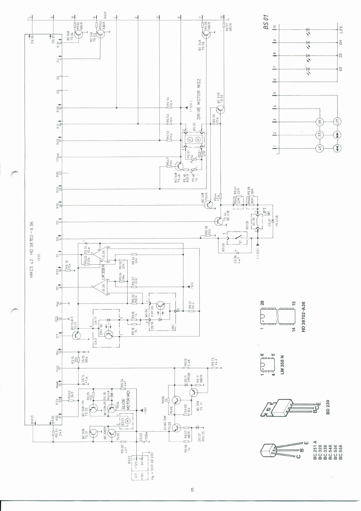
Prozessor HD 38702-A 36 (lS 01) . Pin Connection . Pinbelegung
Pin Signal
1 J. Opto Sensor OS 1, OS 2 ON
2
3
4+ I LEDSrarr{ON
5 e 1 Contact S1 closed
6 - J Solenoid M1 ON
7 e flfLfL Oplo Sensor OS 2 (Counter)
B e fL Opto Sensor OS 1 flracking)
9 0 Volt
10e JL Reset
'11 + 2,7 Voll
12 + 12 Volt
13 e 5511 Oscillator 400 kHz
14 UBAT + 12 Volt
Remarks . Bemerkungen
Switch <, <<
Switch <, <<
Lift Up .Tonarm abgehöben, LiftkontaK 51 geschlossen
Lift Down .Tonarm abgesenkt
Counterpulse from driving wheel . Zählimpulse Antriebsrad
tangential tracking error < 90" . tangentialer Spurfehlwinkel < 90'
Power ON .Spannung ein
saw tooth . Sägezahn
search scan lefyright, fast or slow
Tonarm Rechts- und Linkslauf, langsam oder schnell
Switch 33
Switch 45
Switch Start <, <<
Switch 45, Switch (
Switch 33, Switch >>
Switch Start {, Switch Lift t
+ 12 Volt
15+ J
16+ J
17+ I
18
lv+
20-
21 +
22+
ZJ
24 + -f LED 33 ON, Drive Motor MO 2 33 Upm
25 - I LED 45 ON, Drive l\,4otor MO 2 45 Upm
26 + J Drive Motor MO 2 ON
27 + ;111 Pulse for Switch Matrix t,
28 + JLflJl Pulse for Switch N/latrix <, 33, 45
Signification . Bezeichnung:
4 + Output
7 + lnput
f Signal HIGH aclive
I Signal LOW active
slow left . Linkslauf langsam
quick left . Linkslauf schnell
slow right Rechtslauf langsam
quick right . Rechtslauf schnell
Signification . Bezeichnung:
H = ca. 11,5 V DC
L:ca, 0,2VDC
X:ca. 8 VDC
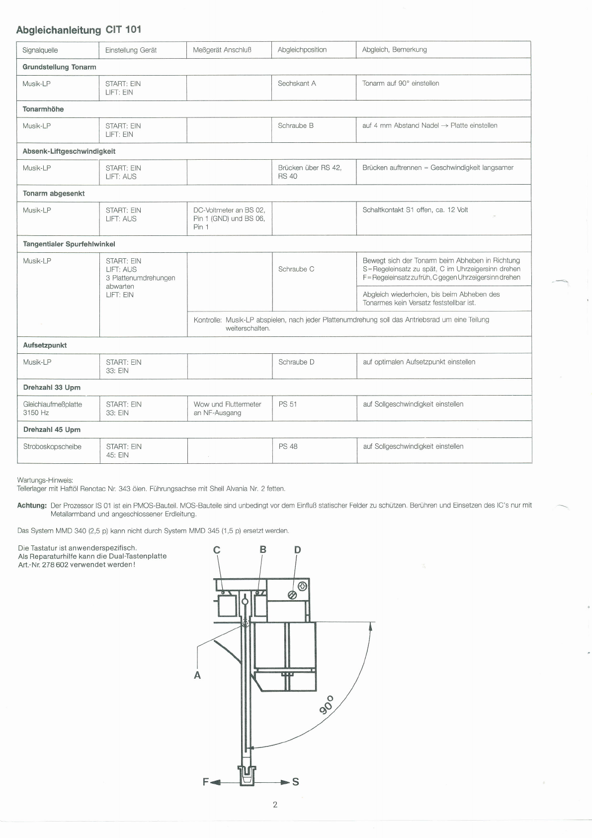
Test Gear Connection . Meßbedingung
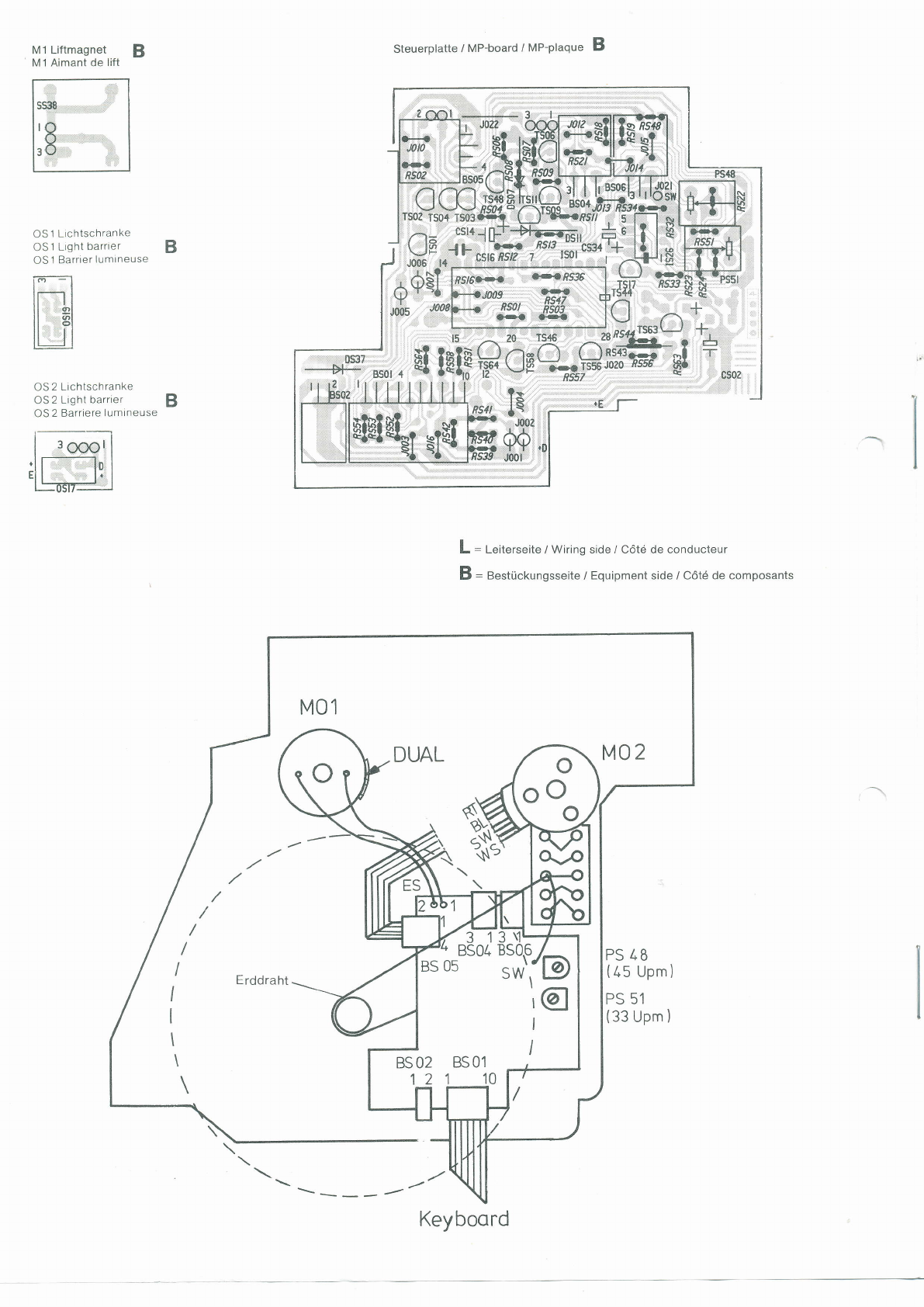
OS 1: Opto Sensor Tracking, in the tonearm . Lichtschranke im Tonarm für Spurfehlwinkel
OS 2: Opto Sensor Counter, on the driving wheel . Lichtschranke am Antriebsrad
MO 1: Slide Motor . Tonarmvorschubmotor
MO 2: Drive Motor . Plattentellerantriebsmotor
S 1: Contact Lift . LiftkontaK
M 1: Solenoid Lift ' Liftmagnet
Logic Matrix Slide Motor MO 1
Pin ES
10,5 V
10,5 V
9V
1,2V
8,7 V
0,9 v
connector.stecker Bs 02 fJl-t_-]
Dosciroskop,vlr

s
V1
a
Pe
N
O
t
O
F
o
L!
=
O
rx
R!
pl
a-F
tir
-
I
l3
t-
I
;;
9t
+il I
33 Pe
@
I
O
N
@
o
r_
N
j
O
T
ro(o
F(9
Co
N*
b \t lp
l. {\ I O
tTrrüd bErrrrrr/ (9
+Q
F!
I
__l
l-t
l' ao|{) I
l16
D l3
k-J =
FeJ
l! FOOCO(oCO
loNori|nn
NOOOOO
oooooo
o(odldl.D()
P-
!@
I r-H
Hi-l ^l i ;
t:] o
l' li
läili

Ersatzteile . Replacement parts . Piöces d6tach6es .ClT 101
Pos. Art.-Nn Stck Bezeichnung
1
2
4
5
6
10
11
12
14
15
16
17
18
19
20
26
27
28
29
30
31
35
39
40
41
44
46
47
47
48
50
220212
27 4787
277 916
277 917
272489
277 918
277 919
277 920
277 921
277 922
276241
277 923
277 924
210 1 44
274968
276244
277 386
277 926
27 4 415
214 1 47
274960
277 927
274966
276627
277 929
277 930
277 931
277 932
272852
276941
277 003
230 063
274979
Zentrierstück
Plattentellerbelag
Plattenteller kpl,
Antriebsteller
Flachriemen
lvlotorbef esti gu n gsteile
Motor DC 160 kpl,
Motor DD 260 kpl.
Tellerlager
Grundplatte
Aufnahmetopf mit Gummipuffer
Befestigungsteile
Vierkantriemen
Scheibe 1,9
Antriebsrad
Transportsicherungsachse
Fuhrungsschiene
Gleitstange
Scheibe 4
Dual-Zeichen
Abdeckung
Zahnstange
Befestigungsschraube
Tonarm kpl,
Tonarmleitung kpl,
Tonarmlager kpl,
Schlitten
Gewindestift M 2,5x0
Zugfeder (MMD 340)
Zugfeder (MMD 345)
Gewindestift
Heberbolzen
Das System IVMD 340 (2,5 p) kann nicht durch System MNID 345 (1 ,5 p) ersetztwerden
The cartridge N/MD 340 (2.5 p) can not be replaced by the cartridge N/N/D 345 (1 5 p)
NF-Anschlußplatte Ausf. 1 |
NF-Connection board
NF-Plaque de branchement
R (red)
R (GND)
GND
L (GND)
Erddraht
L (withe)
NF-Anschlußplatte Ausf. 2 |
NF-Connection board
NF-Plaque de branchement
GND
R (red)
R (GND)
Erddraht
L (GND)
L (withe)
II
R
L
R
GRiGL
L
6
Pos, Art.-Nr. Stck Bezeichnung
65
DS7
DS 11
DS 37
töl
rs 26
os 19
TSl
TS2
TS3
TS4
TS6
TS9
TS 17
TS 44
l5 4t)
TS 48
TS 56
TS 58
TS 63
TS 64
52
53
54
55
57
58
59
60
61
277 007
276626
277 933
276 805
27 4974
276657
277 934
274414
276635
277 935
227 36A
244534
223906
277 938
276024
277 939
231 066
277 936
ZJ UOO
277 936
238 894
238894
244715
231 066
231 066
244715
277 937
244715
244715
244715
277 242
1
1
1
1
1
1
1
1
1
1
,1
1
1
1
1
2
4
2
4
2
3
3
5
4
4
5
2
5
5
5
1
Gewindestift
Abdeckung
Lichtschranke OS2
DrucKeder
Rolle
Buchse
Magnet kpl,
Steckerhalterung
NF-Anschlußplatte
Steuerplatte
Diode ZPD /,5
DiodeBZXT9C6Vg
Diode 1 N 4148
tc uP HD 38702 A 34
IC LIV 358 N
Gabelkoppler CNY 36 OS 1
Transistor BC 338-25
Transistor BC 328-25
Transistor BC 338-25
Transistor BC 328-25
Transistor BC 338
Transistor BC 338
Transistor BC 548 C
Transistor BC 338-25
Transistor BC 548 C
Transistor BC 558
Transistor BC 548 C
Transistor BC 548 C
Transistor BC 548 C
Bedienungsanleitung CIT 1 01
Anderungen vorbehaltenl / Subject to changel / Sous r6serve de modificationl
GF]/GL

O--- m
isg) \
(40)
+g
L9
?l?
t1r
I
ARL
=lffiTffi
-ti:&i*{}4ts
'\!ESv
Iffi
,al) -\./
e'
R,
-@

M1 Liftmagnet
M 1 Aimant de lift
OS 1 Lichtschranke
OS 1 Light barrier
OS 1 Barrier lumtneuse
OS 2 Lrchtschranke
OS 2 Light barrier
OS 2 Barriere lumineuse
BSteuerplatte / MP-board / MP-plaque B
L = Leiterseite / Wiring side / Cötd de conducteur
B = Bestückungsseite / Equipment side / Cötd de composants
DUAL M02
PS /,8
(45 Upm)
PS 51
(33 Upm )
B
I
B
.$
Erddraht
'\----'/
BS 0s sw','l_g)
\o
BS02 BSOl
Keyboord
Table of contents
Languages:
Other Dual Turntable manuals