Alwaysde-energize unit before removing cover.
Theinstallationof the unitsmustbein
accordancewithanylocal codesthat mayapply
and shouldonlybecarriedout byacompetent
trainedelectrical engineer.
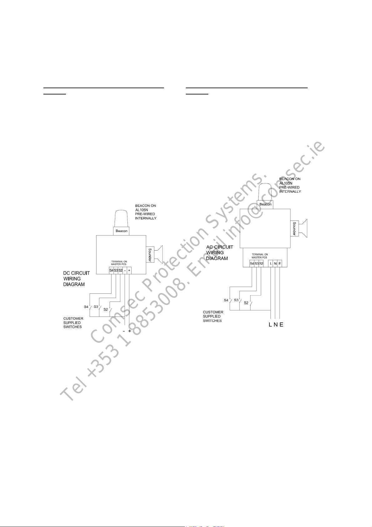
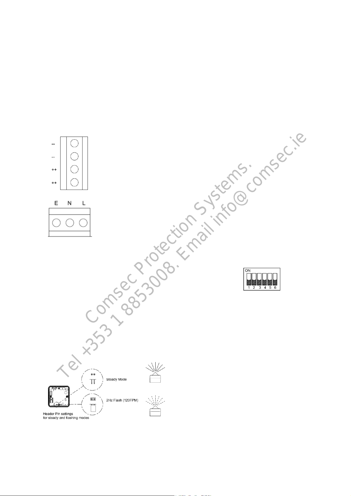
Thepowerterminalson thecontrol unit are
clearlymarkedandwill acceptupto 1.5mm2
cable.
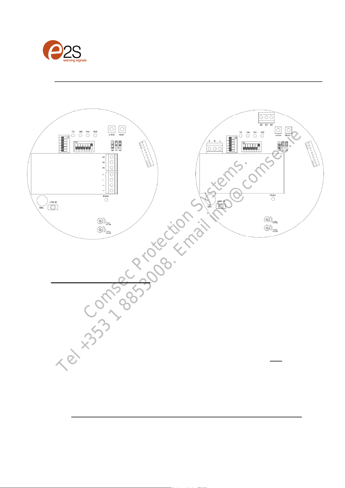
DC Terminals
on mainPCB.
++ =Positive
--=Negative
ACTerminals
OnSub PCB
L=Live
N=Neutral
E=Earth
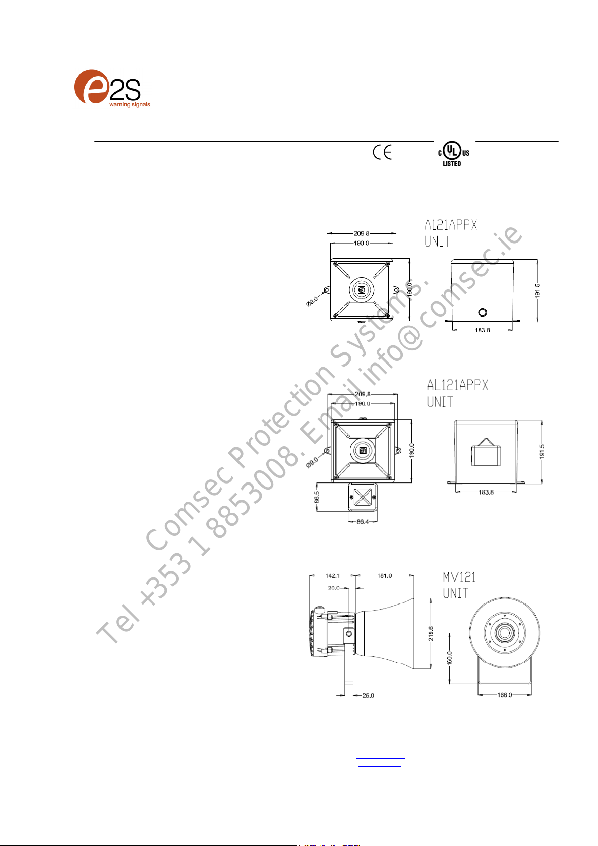
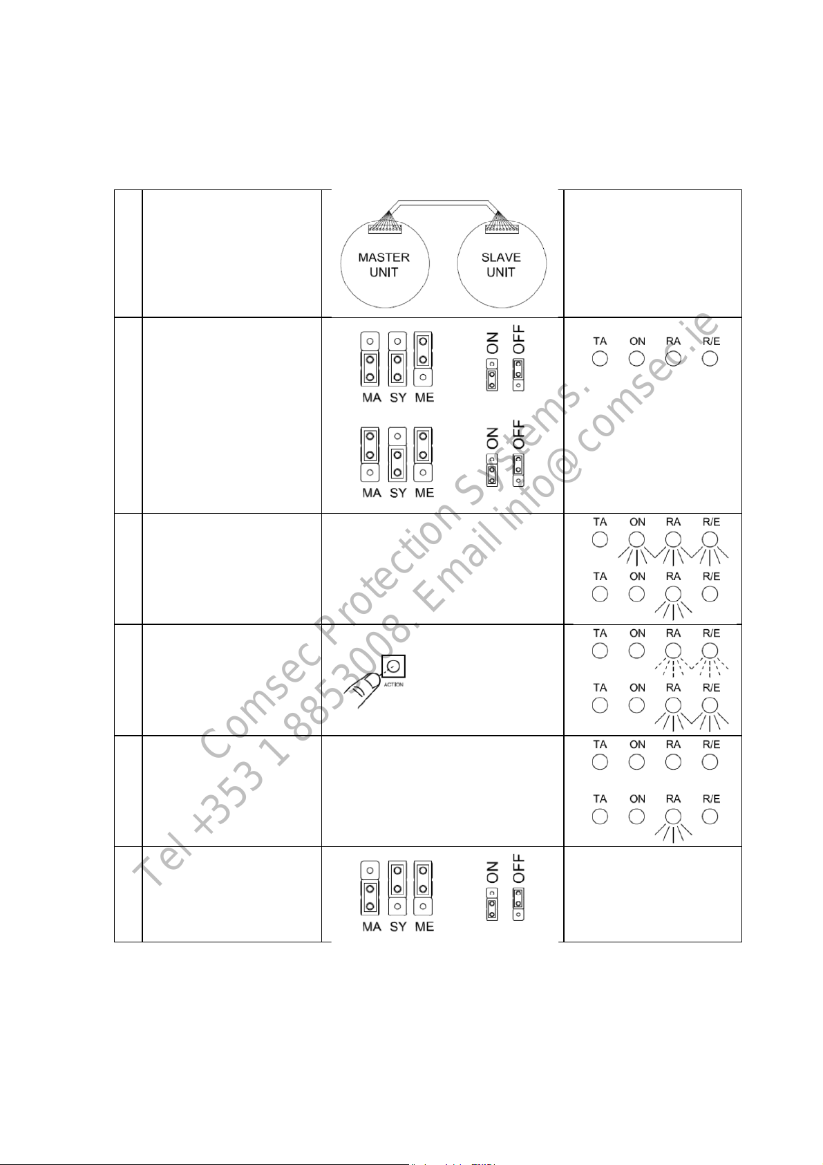
TheAL121unitswill havethe beaconalready
prewiredto the unit so no extrawiring isrequired.
4)BeaconSet-up
The beaconunitmayneedto beconfigured
dependanton the type of flashrequired.
The xenon beacon hasa1Hzflash rate only.
The LED beaconisset as standard tothe2Hz
flash modebutit can beset to a steady on mode
also. To alter the settings,change the position of
theheader pin asshown.
•Removeheader for steadymode.
•Keepheader in standardposition for
2Hzflashingmode
5)UnitSet-up and Recording
The unit will needto be configured to suit theend
user.
Ifrecording eithervia the onboardmicrophoneor
thein-line connectortheunitwill need tobe
supplied with power.
DC unitscanbe poweredwhencompleting
recording and set-up.
Warning!: During set-up on AC units care
must be takennotto touch thelive terminals.
Thisis because on the ACunitsthere is arisk
of electricshock.
See section 7) AppelloSetupGuide overleaf for
Set-up instructionsandfunctions.
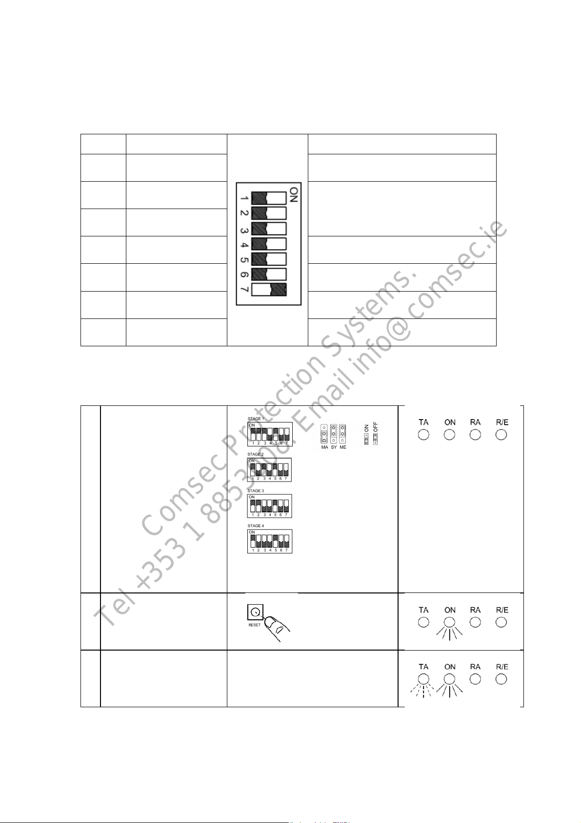
6)ToneSelectionTable
The Appellounithas45different tones(See
Table 1)thatcan beselected for the firststage
alarm. Thesystemscanthenbeswitched to
sound second, thirdand fourth stagealarmtones.
The tonesare selectedbyoperation ofaDIP
switch S4on themain PCB.
The tonetable (Table1)shows the switch
positionsfor the45 tonesandwhichtonesare
available for the second third andfourth stages.
Example
S4Dip Switch -
ShownSetfor Tone1
(AllswitchesOFF)
To soundstageonesimplyconnectthesupply
voltage(+veand –ve)for DCunitsand(L,N, E)
forAC units,tothesupply input terminalsonthe
correctPCBshown.
Comsec Protection Systems.
Comsec Protection Systems
26 Stadium Business Park, Ballycoolin Rd. Dublin 11