Eco FSA ECO SR-EFR BG User manual
1/23
F
Für die Montage dürfen ausschließlich Originalteile des Herstellers verwendet werden.
Die Montagearbeiten müssen gemäß Anleitung von einer qualifizierten Person
durchgeführt werden. Bei Nichtbeachtung entfällt jeglicher Garantieanspruch. Diese
Anleitung ist vom Monteur nach der Montage an den Betreiber weiterzugeben!
Only original parts have to be used. The assembly has to be made by a qualified person
according to the mounting instruction. In case of non-respect the guarantee is invalid. This
instruction is to be handed over to the operator by the fitter after assembly!
Impérativement utiliser la notice de montage fournie par le fabricant. La mise en œuvre et
le montage doivent être exécutés par du personnel qualifié. Le non respect de ces règles
annule catégoriquement tout droit de garantie. Cette instruction est à remettre par le
poseur à l’exploitant après montage.
Leistungserklärung nach Verordnung (EU) Nr. 305/2011 finden Sie unter http://www.eco-schulte.de/leistungserklaerungen
Declaration of performance according to Regulation (EU) No 305/2011 see http://www.eco-schulte.de/declarationofperformance
Déclaration des performances conformément au règlement (UE) N° 305/2011 voir http://www.eco-schulte.de/declarationdesperformances
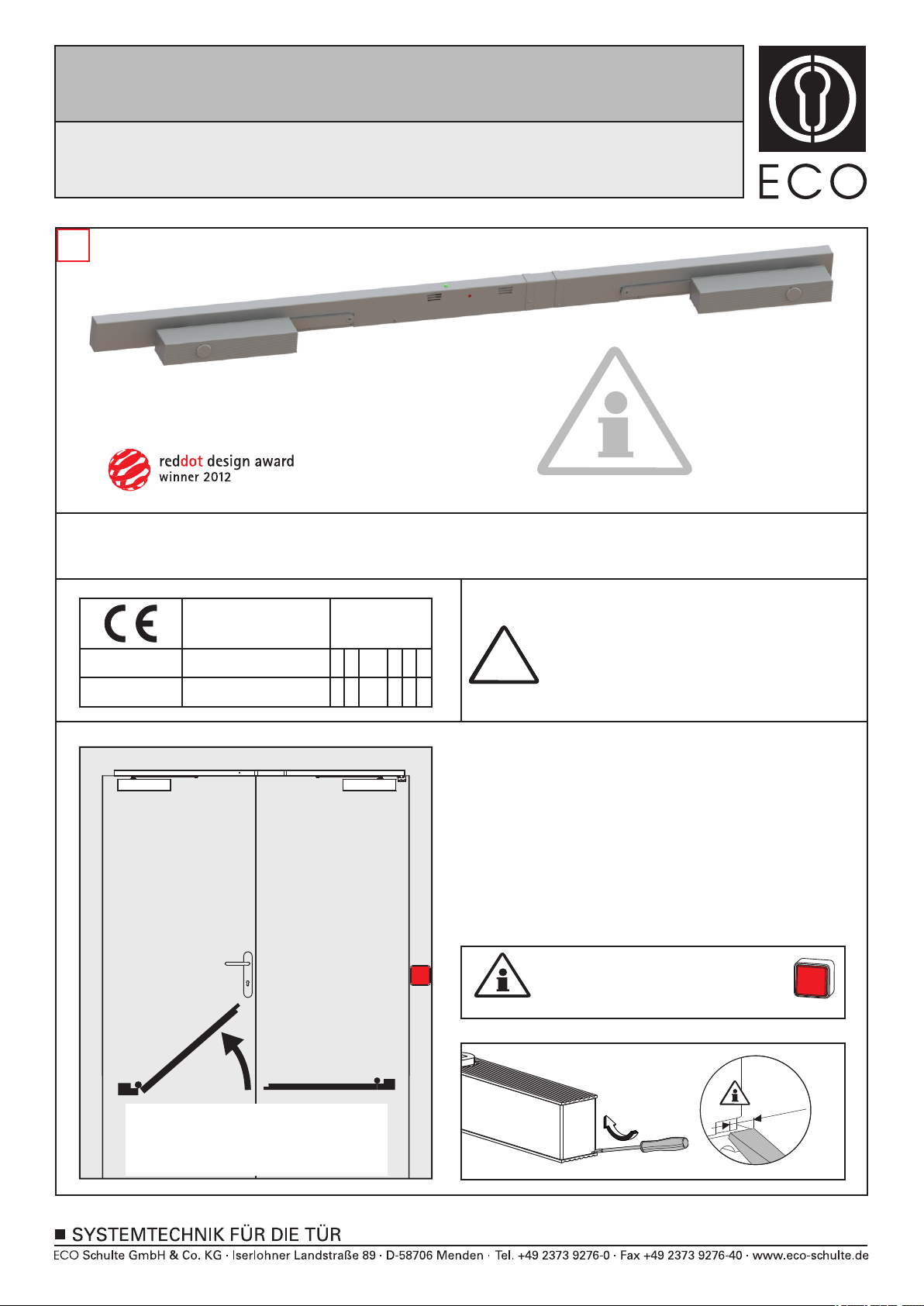
GS
DIN links - spiegelbildlich
DIN left - mirror image
DIN gauche - inverser l´illustration
Tür
schließen
!
Für die Montage sowie die Ventileinstellungen des Türschließers
beachten Sie bitte die dem Türschließer beiliegende separate
Montageanleitung.
Please refer to the enclosed assembly instruction of the doorcloser
for mounting as well as adjusting the valves of the doorcloser.
Pour le montage et le réglage des ferme-portes, merci d'utiliser la
notice de pose incluse séparément.
3-5 01 13 8
06
0432 - CPD - 0147 EN 1158:1997+A1:2002 /
AC:2006
0432 - CPD - 0143 EN 1155:1996+A1:2002 /
AC:2006
ECO Schulte GmbH & Co. KG
Iserlohner Landstraße 89
D-58706 Menden
3-5 31 13 5
Bei Vollpanikfunktion ist eine Mitnehmerklappe MK Basis 2 zu
montieren.
Nicht im Lieferumfang enthalten!
With full panic function, a panic flap MK Basis 2 must be installed.
Not included in the delivery!
En cas de montage d'Anti-paniques sur les deux vantaux, il faut
utiliser l'entraineur MK Basis 2.
(N'est pas compris dans la livraison, à commander
séparément)
Handtaster muss gesetzt werden!
A manual button must be installed!
Installez un bouton poussoir!
Tür
schließen
max.
3,5mm
Montageanleitung / Assembly instruction / Notice de montage
FSA ECO SR-EFR BG
FSA ECO SR-EFR BG
FSA ECO SR-EFR BG
(DIN rechts / DIN links spiegelbildlich)
(DIN right / DIN left mirror image)
(DIN droite / DIN gauche inverser l‘illustration)
© ECO Schulte GmbH & Co. KG / Änderungen vorbehalten! / SR-EFR BG / MTS00568 / 33920000568 / Index: b
2/23
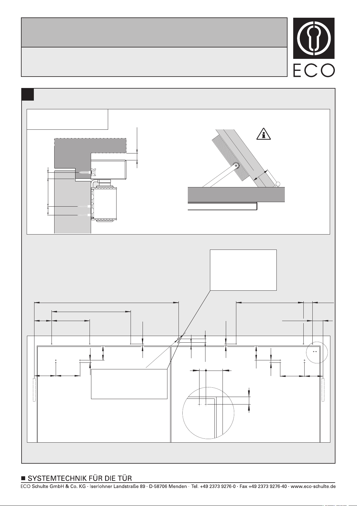
1a
122
53
A
160
16
122
160
16
53
974,5
120
546
13
446
60,5
59,5
13
18 46
20
A
Bohrung für elektrischen
Anschluss (230V)
Drilling for electrical
connection (230V)
Alésage pour raccordement
électrique (230V)
X
X = 60-92mm
Direktmontage (ohne Unterprofil)
Direct mounting (without underprofile)
Montage direct (sans sous profil)
GS
Bohrung für zusätzliche Anschlüsse
Drilling for additional electrical
connections
Alésage pour les connexions
électriques supplémentaires
17
2x ø10
10
16 13
53
min. 10mm
290
Montageanleitung / Assembly instruction / Notice de montage
FSA ECO SR-EFR BG
FSA ECO SR-EFR BG
FSA ECO SR-EFR BG
(DIN rechts / DIN links spiegelbildlich)
(DIN right / DIN left mirror image)
(DIN droite / DIN gauche inverser l‘illustration)
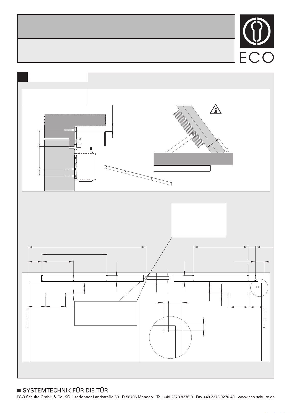
1b
3/23
X
X = 60-92mm
Montage mit Adaptionsprofil
Mounting with adaptor plate
Montage avec profil d’adaptation
(optional, optional, optionnelle)
122
A
160 122
160
16
53
974,5
120
33
446
60,5
59,5
33
18 46
20
A
Bohrung für elektrischen
Anschluss (230V)
Drilling for electrical
connection (230V)
Alésage pour raccordement
électrique (230V)
53
16
GS
Bohrung für zusätzliche Anschlüsse
Drilling for additional electrical
connections
Alésage pour les connexions
électriques supplémentaires
17
2x ø10
10
290
546
16 33
53
min. 10mm
Montageanleitung / Assembly instruction / Notice de montage
FSA ECO SR-EFR BG
FSA ECO SR-EFR BG
FSA ECO SR-EFR BG
(DIN rechts / DIN links spiegelbildlich)
(DIN right / DIN left mirror image)
(DIN droite / DIN gauche inverser l‘illustration)
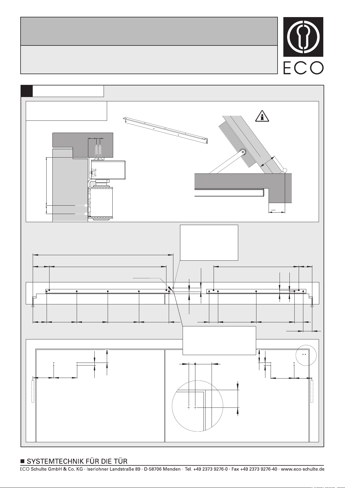
1c
4/23
X = 65-92mm
122
95
A
160
16
122
160
16 95
18 46
62
A
984,5
138,5
121 205
205 212 212
799
17
582 90,5
60
261
261
60
Bohrung für elektrischen
Anschluss (230V)
Drilling for electrical
connection (230V)
Alésage pour raccordement
électrique (230V)
60,5
17
24
Montage mit Sturzfutterwinkel
Mounting with under-lintle angle
Montage sous linteau avec équerre
X
33
<
GS
20
Bohrung für zusätzliche Anschlüsse
Drilling for additional electrical
connections
Alésage pour les connexions
électriques supplémentaires
2x ø10
16 95
717
(optional, optional, optionnelle)
Montageanleitung / Assembly instruction / Notice de montage
FSA ECO SR-EFR BG
FSA ECO SR-EFR BG
FSA ECO SR-EFR BG
(DIN rechts / DIN links spiegelbildlich)
(DIN right / DIN left mirror image)
(DIN droite / DIN gauche inverser l‘illustration)
5/23
3a
2
2
2
3
3
4
1
2
2
1
1
2
1
1
1
Montageanleitung / Assembly instruction / Notice de montage
FSA ECO SR-EFR BG
FSA ECO SR-EFR BG
FSA ECO SR-EFR BG
(DIN rechts / DIN links spiegelbildlich)
(DIN right / DIN left mirror image)
(DIN droite / DIN gauche inverser l‘illustration)
Other manuals for FSA ECO SR-EFR BG
1
Other Eco Door Opening System manuals


 User manual")


Popular Door Opening System manuals by other brands


Besam
Besam Swingmaster MP Installation, adjustment and maintenance instructions

Assa Abloy
Assa Abloy SARGENT 1431 Series instructions

GAL
GAL MOVFR Quick setup

Häfele
Häfele Finetta T 70 VF manual

AGS
AGS D-PL Instructions for fitting, operating and maintenance

Stanley
Stanley MA900ñ Installation and owner's manual

WITTUR
WITTUR Hydra Plus UD300 Instruction handbook

Alutech
Alutech TR-3019-230E-ICU Assembly and operation manual

Pamex
Pamex KT-INP35 Installation instruction

MPC
MPC ATD ACTUATOR 50 ATD-313186 Operating and OPERATING AND INSTALLATION Manual

Chamberlain
Chamberlain T user guide

Dorma
Dorma MUTO COMFORT M DORMOTION 50 Mounting instruction