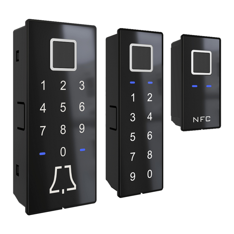
Eco SR Basis 2 User manual

Technische Daten:
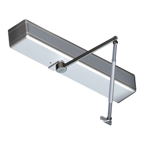
Werden die beiden Türflügel einer Tür geöffnet, so
richtet sich der Teleskoparm des Schließfolgereglers
SR Basis 2 aufgrund der integrierten Schenkelfeder
automatisch auf.
Funktionsweise:
Der Schließfolgeregler bestimmt die Schließreihen-
folge der beiden Türflügel: der Schloßflügel, der zu-
letzt schließen soll, stößt mit dem Zapfen seines
Stützwinkels auf den federnd gelagerten Teleskop-
arm des Schließfolgereglers und bleibt in dieser
Stellung ...
... bis der Riegelflügel beim Schließen mit seinem
Mitnehmerzapfen seitlich an den Teleskoparm des
Schließfolgereglers gelangt und ...
... den Teleskoparm des Schließfolgereglers flach an
die Türzarge klappt. Dadurch wird der Schloßflügel
freigegeben, so dass ...
... der Schloßflügel ebenfalls vollständig schließen
kann.
Türflügelgewicht:
max. 200kg je Türflügel
Türflügelbreite:
bis 1,60m je Türflügel
Platzbedarf oberhalb der Tür:
min. 30 mm
Oberfläche:
galvanisch verzinkt (silberfarbig)
Lieferumfang
Schließfolgeregler, 2 Stützwinkel
6 Schrauben M8
SYSTEMTECHNIK FÜR DIE TÜR
www.eco-schulte.deFax. 0(23 73) 92 76-70Tel. 0(23 73) 92 76-058706 MendenIserlohner Landstraße 89
ECO Schulte GmbH & Co. KG
Montage-Anleitung Schließfolgeregler ECO SR Basis 2
1
©ECO Schulte GmbH & Co.KG / Änderungen vorbehalten! / SR Basis 2 / MTS15008 / 339206101 / Index: b

Montage:
Entnehmen Sie die Montageabstände dem Diagramm
und der Skizze.
Befestigen Sie zuerst die beiden Stützwinkel mit den
beiliegenden Innensechskant - Senkkopfschrauben
(M8x16 Din 7991) an den vorderen oberen Ecken der
beiden Türflügel. Die Montagepunkte finden Sie in
der Zeichnung.
Montieren Sie als nächstes den Schließfolgeregler
mit den beiliegenden M8x16-Schrauben an der Tür-
zarge. Die Senkkopfschraube ist für die Bohrung mit
Senkung bestimmt, die Kopfschraube für das Lang-
loch. Achten Sie darauf, dass der Schließfolgeregler
im angeklappten Zustand genau waagerecht zum
Türsturz verläuft. Sie können die waagerechte Aus-
richtung korrigieren, indem Sie die M8-Kopfschraube
im Langloch lockern und das Fußstück um die Senk-
kopfschraube drehen.
Beachten Sie bitte, dass der Teleskoparm in aufge-
richteter Stellung genau auf den Zapfen am Stütz-
winkel des Schloßflügels trifft. Mit der Einstell-
schraube am Fuß des Schließfolgereglers können
Sie den Aufrichtewinkel justieren. Ziehen Sie da-
nach die Kontermutter wieder gut fest .Mit den 4
Einstellschrauben auf der Befestigunsplatte können
Sie die waagerechte Position des Schließfolgereglers
einstellen.
Wartung:
Fetten oder Ölen des Schließfolgereglers ist nicht
notwendig. Reinigen Sie den Schließfolgeregler von
Zeit zu Zeit und prüfen Sie dabei den korrekten
Aufrichtewinkel sowie den waagerechten Sitz an
der Türzarge.
Achtung:
Bei Türelementen mit Fluchttürfunktion und Brand-
schutz-Anforderung ist die Montage einer Mitneh-
merklappe erforderlich.
(siehe separate Montageanleitung)
Die Montageanleitung ist dem Betreiber auszuhän-
digen und von diesem aufzubewahren.
Montage-Anleitung Schließfolgeregler ECO SR Basis 2
www.eco-schulte.deFax. 0(23 73) 92 76-70Tel. 0(23 73) 92 76-058706 MendenIserlohner Landstraße 89
ECO Schulte GmbH & Co. KG
SYSTEMTECHNIK FÜR DIE TÜR
2
3
0432-CPD-0147 EN 1158:1997
+A1:2002 357
3114
04
ECO Schulte GmbH & Co. KG
Iserlohner Landstraße 89
D-58706 Menden
1
2
280
240
220
200
180
160
700 800 900 1000 1100 1200 1300
Türflügelbreite B in mm
Anschlagmaß A von Mitte Tür bis
Drehpunkt Schließfolgeregler in mm
140
120
1400 1500600500
260
1600
Türdicke 60 mm
Türdicke 80 mm
Türdicke 100mm
Riegelflügel Schlossflügel
(Türflügelbreite B)
A
S
Das Anschlagmaß A sollte
so gewählt werden, dass bei
Schließen des Riegelflügels
ein Sicherheitsspalt S von
mindestens 30mm frei bleibt.
Das Anschlagmaß A sollte
so g ewählt w erden, d ass d ie
Mitnehmerklappe den Schloß-
flügel so weit aufdrückt bis
der Schließfolgeregler ihn
abstützt.
Maße
20
45,5
60
120
535
Senkung
Bm8 DIN 74
ø22
ø18
9
30
Mutter M8 DIN 439 SW 13
M8x20 mit Innen
4
47
max. 72°
min. 30°
45
Anschlagmaß A
40
50
25
50
45
80
113
23
80
ø16
Türzarge
8,1
sechskant SW 4
Türblatt
1
34 x M5
2
Leistungserklärung nach Verordnung (EU) Nr. 305/2011 finden Sie unter http://www.eco-schulte.de/leistungserklaerungen
Declaration of performance according to Regulation (EU) No 305/2011 see http://www.eco-schulte.de/declarationofperformance
Déclaration des performances conformément au règlement (UE) N° 305/2011 voir http://www.eco-schulte.de/declarationdesperformances
©ECO Schulte GmbH & Co.KG / Änderungen vorbehalten! / SR Basis 2 / MTS15008 / 339206101 / Index: b

Technical data:
Weight of one door leaf:
max. 200kg
Width of one door leaf:
up to 1,60m
Required space above the door:
min. 30 mm
Finish:
zinc plated galvanized steel
Elements of delivery:
door sequence selector, 2 brackets
6 screws M8
SYSTEMTECHNOLOGY FOR THE DOOR
www.eco-schulte.deFax. 0(23 73) 92 76-70Tel. 0(23 73) 92 76-058706 MendenIserlohner Landstraße 89
ECO Schulte GmbH & Co. KG
Fitting Instructions Door Sequence Selector ECO SR Basis 2
Every time both door leaves are opened, the telescopic
arm of the door sequence selector ECO SR Basis 2 is
put automatically upright by the integrated leg spring.
The door sequence selector controls the right closing
sequence of both door leaves:
The active door leaf that has to be the last to close hits
with the pin of the support bracket the telescopic arm of
the door sequence selector and is kept in this position ...
... until the (latch) leaf comes with its support bracket
laterally across the telescopic arm of the door sequence
selector and ...
... while closing takes the telescopic arm back with it to its
closed position. When the telescopic arm lies flat against
the door frame, the active door leaf is released and ...
... can now close also.
If only the active leaf is opened the door sequence selector
ECO SR Basis 2 stays in its closed position.
As soon as the latch leaf is opened also the door sequence
selector is automatically put upright.
Operation:
3
©ECO Schulte GmbH & Co.KG / Änderungen vorbehalten! / SR Basis 2 / MTS15008 / 339206101 / Index: b

Fitting Instructions Door Sequence Selector ECO SR Basis 2
SYSTEMTECHNOLOGY FOR THE DOOR
www.eco-schulte.deFax. 0(23 73) 92 76-70Tel. 0(23 73) 92 76-058706 MendenIserlohner Landstraße 89
ECO Schulte GmbH & Co. KG
0432-CPD-0147 EN 1158:1997
+A1:2002 357
3114
04
ECO Schulte GmbH & Co. KG
Iserlohner Landstraße 89
D-58706 Menden
280
240
220
200
180
160
700 800 900 1000 1100 1200 1300
Width of the door leaf B in mm
Dimension A: middle of the door to the fulcrum
of the door sequence selector in mm
140
120
1400 1500600500
260
1600
Thicknessof thedoorleaf 60 mm
inactive leaf active leaf
(door width B)
A
S
When establishing the dimen-
sion A provide for a safety gap
Sof min. 30mm when the
inactive leaf is closing.
Whenever the inactive leaf is
opened first the pushing flap
MK Basis-1 must open the ac-
tive leaf at least to a position
where the closing sequence
selector can keep it open.
This is another determinating
factor for the dimension A.
Measurements
Thicknessof thedoorleaf 80 mm
Thicknessof thedoor leaf 100 mm
20
45,5
60
120
535
Lowering
Bm8 DIN 74
ø22
ø18
9
30
Nut M8 DIN 439 SW 13
M8x20 with hexagon
4
47
max. 72°
min. 30°
45
Dimension A
40
50
25
50
45
80
113
23
80
ø16
Door leafDoor frame
8,1
socket SW 4
The door sequence selector is now screwed with M8x16
hexagon socket screws to the door frame. The cylinder
head stud is destined for the oblong hole. Please make
sure that the door sequence selector is running exactly
parallel to the door lintel when close. You can adjust the
horizontal position by loosening the cylinder head stud and
moving the door sequence selector slightly around the
countersunk head screw.
When in an upright position the telescopic arm must hit
exactly on the pivot of the support bracket on the active
leave (the last to close). The upright position of the teles-
copic arm can be adjusted with the adjustment screw at
the base of the door sequence selector. Make sure that af-
ter each adjustment the nut is properly tightened again .
The horizontal position of the sequence selector can be ad-
justed by the 4 adjustment screws on the fixing plate.
In order to establish the right position for the door se-
quence selector, see the chart and the sketch.
First of all fix both support brackets with the hexagon
socket screws (M8x16 DIN 7991) to the upper middle cor-
ners of both door leaves. The exact dimensions for the po-
sition can be found on the drawing.
Lubrification of the door sequence selector is not necessary.
Clean the door sequence selector now and then and verify
its horizontal position on the door frame and the correct up-
right position of the telescopic arm.
Maintenance:
Installation:
In case of any escape route or fire rating of the door these
demands must be taken into account when installing the
sequence controller. The user information should be han-
ded to the user of the unit.
Attention:
2
3
1
4
1
34 x M5
2
Leistungserklärung nach Verordnung (EU) Nr. 305/2011 finden Sie unter http://www.eco-schulte.de/leistungserklaerungen
Declaration of performance according to Regulation (EU) No 305/2011 see http://www.eco-schulte.de/declarationofperformance
Déclaration des performances conformément au règlement (UE) N° 305/2011 voir http://www.eco-schulte.de/declarationdesperformances
©ECO Schulte GmbH & Co.KG / Änderungen vorbehalten! / SR Basis 2 / MTS15008 / 339206101 / Index: b
Table of contents
Languages:
Other Eco Door Opening System manuals

Eco
Eco EF TS-41 User manual
Eco
Eco TS-41 User manual

Eco
Eco TS-41 User manual
Eco
Eco TS-50 User manual

Eco
Eco FSA ECO SR-EFR BG User manual

Eco
Eco FSA ECO SR-EFR BG TS-62 G User manual
Eco
Eco TS-61 B User manual

Eco
Eco SR-EFR III User manual

Eco
Eco FSA ECO SR-EFR BG Quick start guide

Eco
Eco TS-50 User manual
Popular Door Opening System manuals by other brands
Entrematic Group
Entrematic Group Ditec Sector Reset installation manual
GEZE
GEZE TS 5000 R quick start guide
Automatic Technology
Automatic Technology GDO-6 EasyRoller Quick operation guide
Dorma
Dorma TS 99 FL Mounting instructions
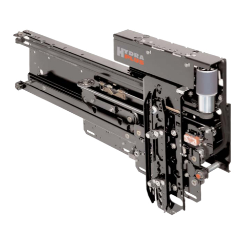
WITTUR
WITTUR Hydra PLUS manual

Assa Abloy
Assa Abloy DC700G-FT Mounting instructions

