13/19
Feststellvorrichtung
Hold open device
Mécanisme de blocage
65432
K1B-+12345
NAG 02
ORS 142W
*
Feststellvorrichtung
Hold open device
Mécanisme de blocage
65432
K1B-+12345
NAG 02
ORS 142W
Feststellvorrichtung
Hold open device
Mécanisme de blocage
65432
K1B-+12345
NAG 02
ORS 142W
Beim Einsatz von Handtastern:
(siehe )
When using manual buttons:
(see )
Lors de l'installation d'un bouton
poussoir: (voir )
2*
1*3*
2*
1*3*
2*
1*3*
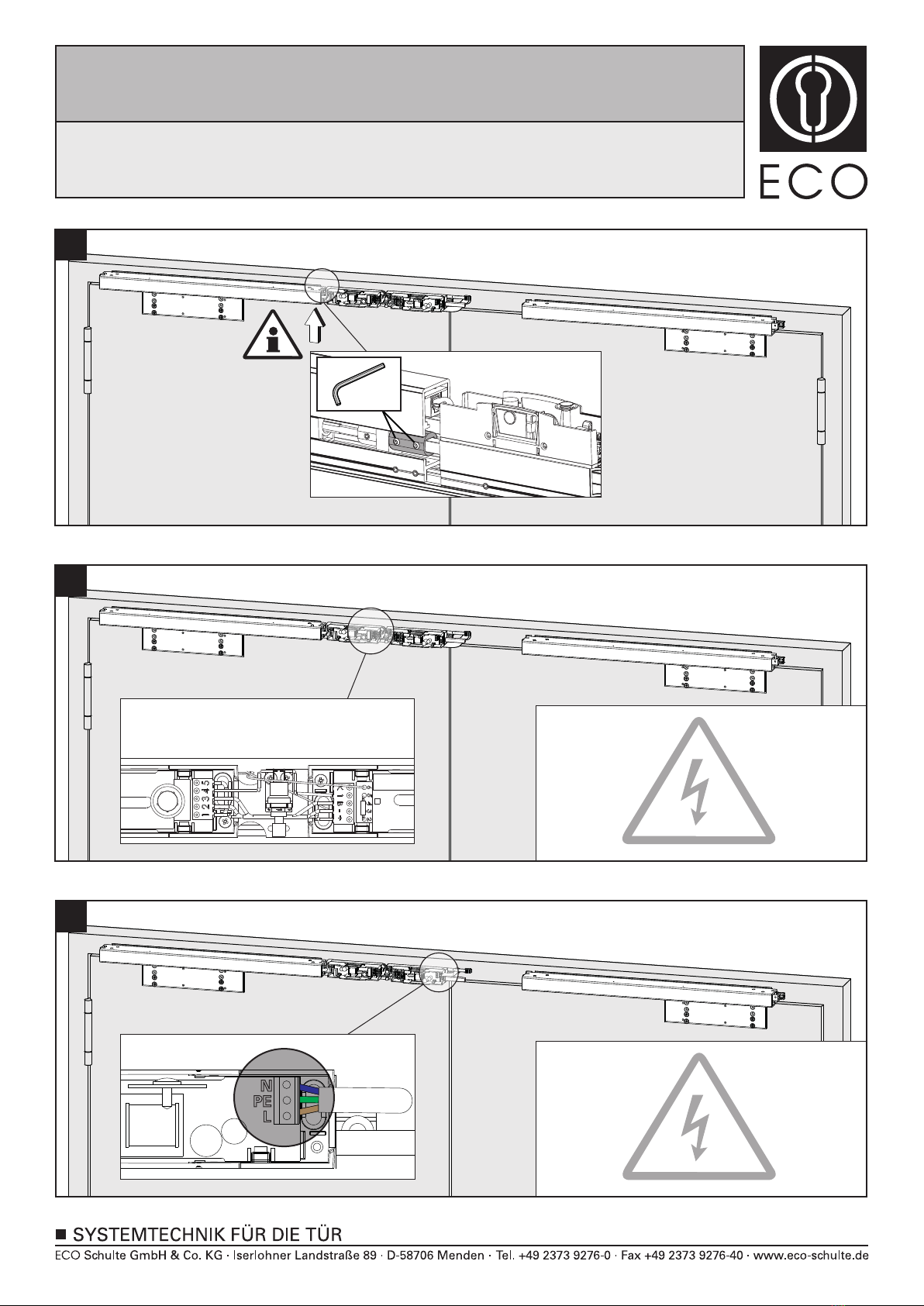
Die elektrischen Anschlüsse müssen gemäß Anleitung von einer qualifizierten Person durchgeführt werden. Bei Nichtbeachtung entfällt jeglicher Garantieanspruch.
Diese Anleitung ist vom Monteur nach der Montage an den Betreiber weiterzugeben!
La mise en œuvre,la connection électrique et le montage doivent être exécutés par du personnel qualifié. Le non respect de ces règles annule catégoriquement tout
droit de garantie. Cette instruction est à remettre par le poseur à l’exploitant après montage.
The electrical installation has to be made by a qualified person according to the mounting instruction. In case of non-respect the guarantee is invalid. This instruction is
to be handed over to the operator by the fitter after assembly!
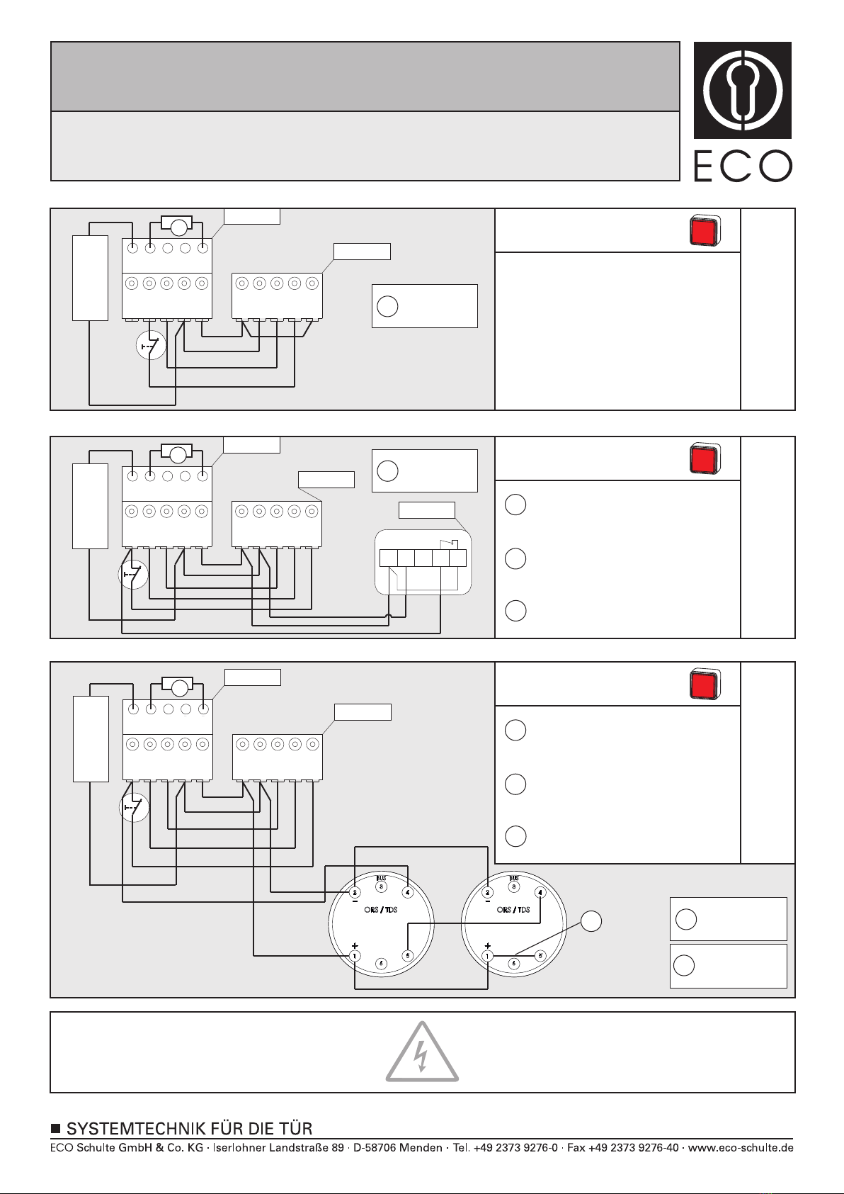
Anschlussplan ohne Deckenmelder
Connectig diagram without ceiling-mounted detectors
Plan de connection sans détecteur
Beim Einsatz von Handtastern wird der vormontierte
Revisionstaster
abgeklemmt. Der neue Taster wird auf Pos. 1 + 4 neu
angeschlossen!
When using manual buttons, then disconnect the pre-
installed revision button. The new button will connect
with Pos. 1 + 4.
Lors de l'installation d'un bouton poussoir, il faut ôter
le bouton pré-installé. Le nouveau bouton poussoir
sera connecté entre la borne 1 et 4.
*
*
Anschlussplan mit Deckenmeldern
Connectig diagram with ceiling-mounted detectors
Plan de connection avec détecteur
Brücke zwischen 1 und 5 entfernen
Remove bridge between 1 and 5
Ôter le pont entre les bornes 1 et 5
Taster von 1 und 4 auf 5 und K verdrahten
Connect push button from 1 and 4 to 5 and K
Connecteur le bouton poussoir de la borne
1 et 4 aux bornes 5 et K
Brücke zwischen 1 und 4 setzen
Set bridge between 1 and 4
Effecteur un pont entre les bornes 1 et 4
1
3
2*
*
*
Beim Einsatz von Handtastern
When using manual buttons
Lors de l'installation d'un bouton
Tür
schließen
RMU 04
123 4 5
BUS
-
+
Brücke zwischen 1 und 5 entfernen
Remove bridge between 1 and 5
Ôter le pont entre les bornes 1 et 5
Taster von 1 und 4 auf 5 und K verdrahten
Connect push button from 1 and 4 to 5 and K
Connecteur le bouton poussoir de la borne
1 et 4 aux bornes 5 et K
Brücke zwischen 1 und 4 setzen
Set bridge between 1 and 4
Effecteur un pont entre les bornes 1 et 4
1
3
2*
*
*
Beim Einsatz von Handtastern
When using manual buttons
Lors de l'installation d'un bouton
Tür
schließen
Beim Einsatz von Handtastern
When using manual buttons
Lors de l'installation d'un bouton
Tür
schließen
*
*
*
Anschlussplan mit Funk-Deckenmeldern
Connecting diagram with wireless ceiling-mounted detectors
Plan de connection avec détecteur de fumeé sans fil
Nicht entfernen!
Don‘t remove!
Ne pas enlever!
4
Nicht entfernen!
Don‘t remove!
Ne pas enlever!
4
4
4
4
Nicht entfernen!
Don‘t remove!
Ne pas enlever!
4
5Brücke setzen
Set bridge
Effecteur un ponte
5
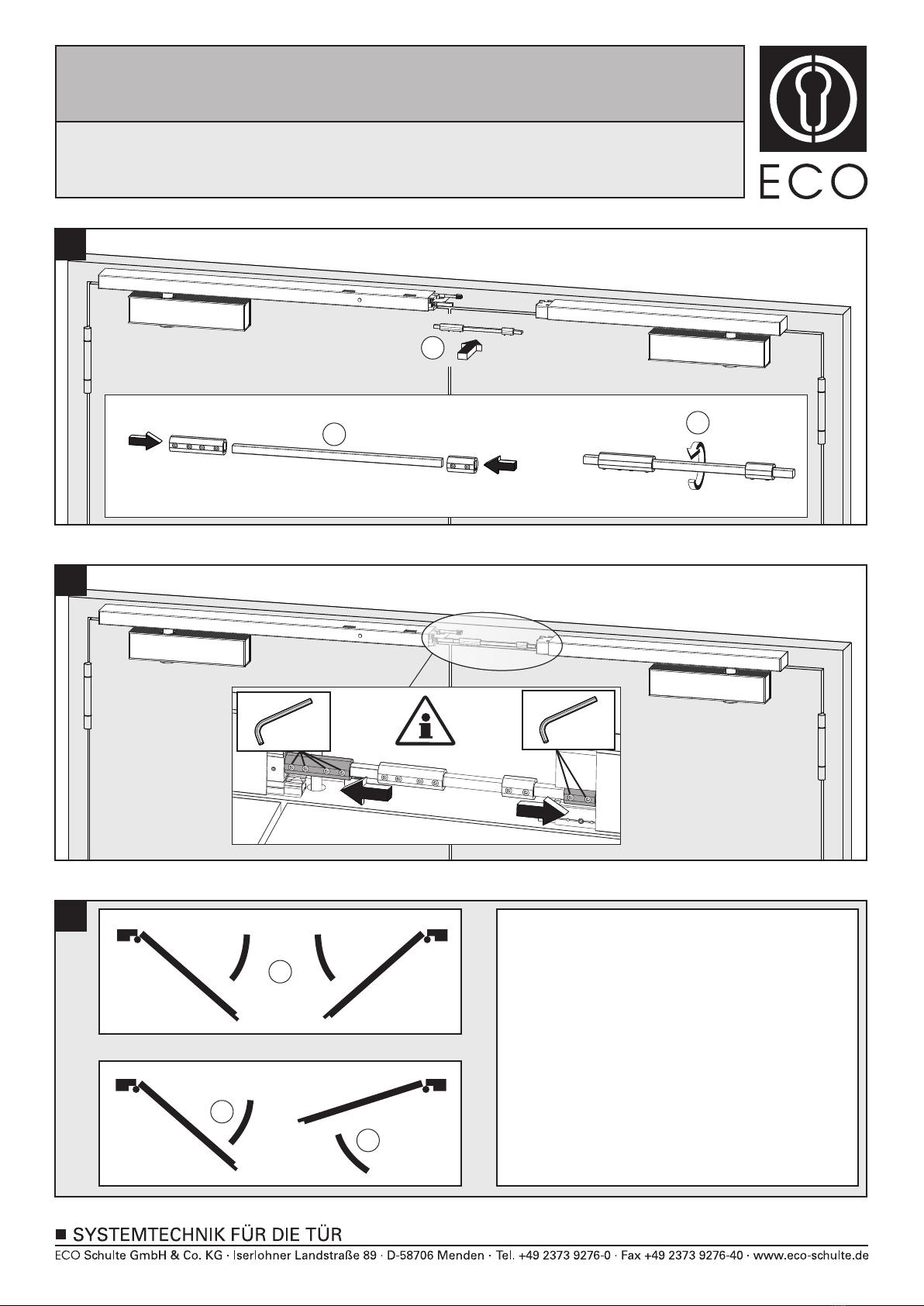
Montageanleitung / Assembly instruction / Notice de montage
FSA ECO SR-EFR mit TS-31 / 41
FSA ECO SR-EFR with TS-31 / 41
FSA ECO SR-EFR avec TS-31 / 41
(DIN links / DIN rechts spiegelbildlich)
(DIN left / DIN right mirror image)
(DIN gauche / DIN droite inverser l´illustration)
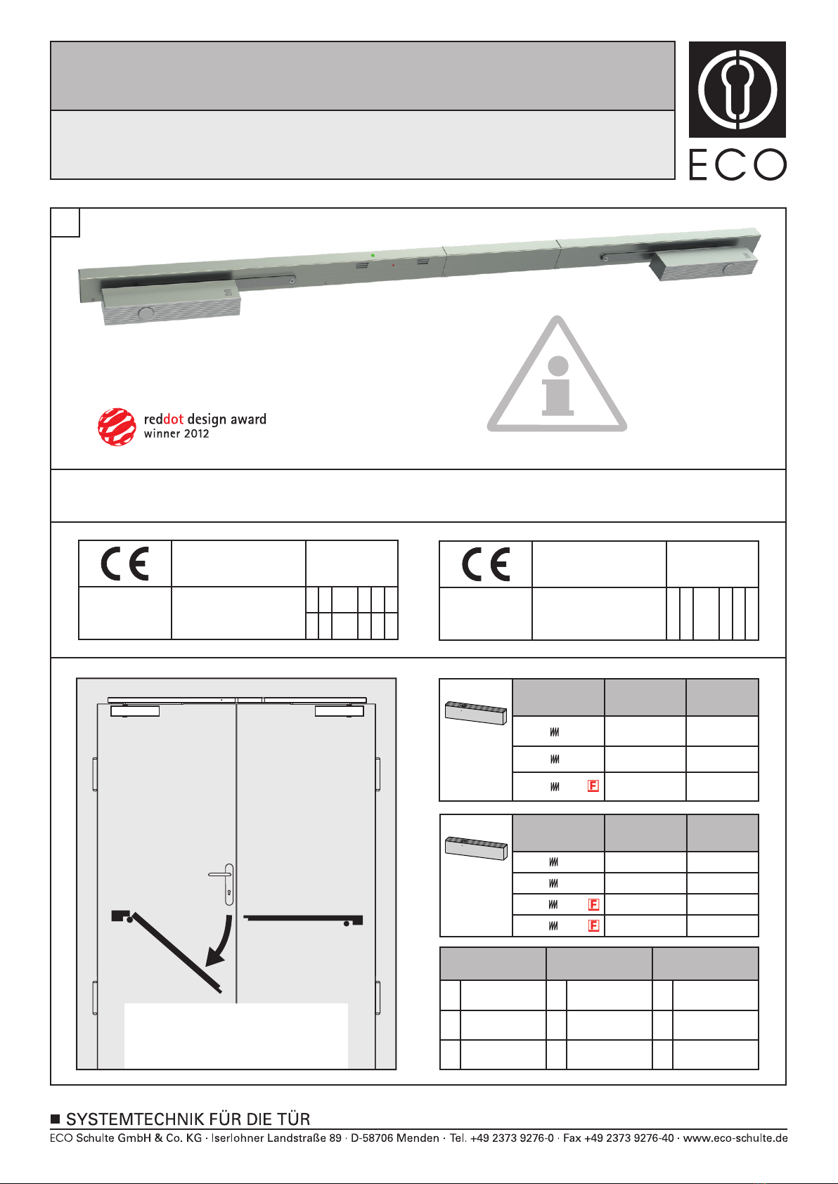


 User manual")


