Eco EF TS-41 User manual
1/11
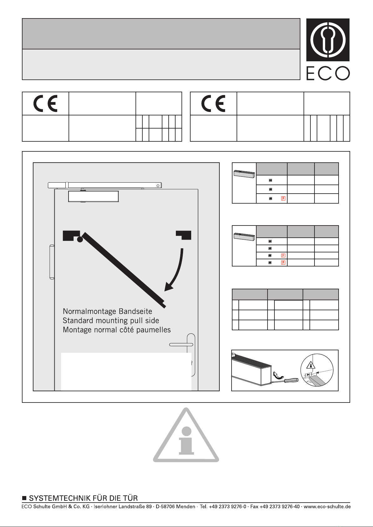
DIN rechts - spiegelbildlich
DIN right - mirror image
DIN droite - inverser l´illustration
Abkürzungen
Schließ-
geschwindigkeit
SG
ES
SK
Endschlag
Schließkraft
CS
Abbreviations Abréviations
Closing speed
LS
CF
Latching speed
Closing force
Vitesse de
fermeture
VF
CF
FF
Coup final
Force de
fermeture
950 mm 0
1100 mm +5
1750 mm -7
850 mm -4
Türschließergröße
Door closer size
Force de ferme porte
Max. Türbreite
Max. door width
Largeur de porte max.
Umdrehungen
Rotations
Rotations
2
3
4
TS-41
EN 1-4
max.
3,5mm
950 mm 0
TS-31
EN 1-3
1750 mm -11
850 mm
Türschließergröße
Door closer size
Force de ferme porte
Max. Türbreite
Max. door width
Largeur de porte max.
Umdrehungen
Rotations
Rotations
2
3
-6
Leistungserklärung nach Verordnung (EU) Nr. 305/2011 finden Sie unter http://www.eco-schulte.de/leistungserklaerungen
Declaration of performance according to Regulation (EU) No 305/2011 see http://www.eco-schulte.de/declarationofperformance
Déclaration des performances conformément au règlement (UE) N° 305/2011 voir http://www.eco-schulte.de/declarationdesperformances
Only original parts have to be used. The assembly has to be made by a qualified person according to the mounting instruction. In case of
non-respect the guarantee is invalid. This instruction is to be handed over to the operator by the fitter after assembly!
Impérativement utiliser la notice de montage fournie par le fabricant. La mise en œuvre et le montage doivent être exécutés par du person-
nel qualifié. Le non respect de ces règles annule catégoriquement tout droit de garantie Cette instruction est à remettre par le poseur
à l’exploitant après montage.
Für die Montage dürfen ausschließlich Originalteile des Herstellers verwendet werden. Die Montagearbeiten müssen gemäß Anleitung von
einer qualifizierten Person durchgeführt werden. Bei Nichtbeachtung entfällt jeglicher Garantieanspruch. Diese Anleitung ist vom Monteur
nach der Montage an den Betreiber weiterzugeben!
Montageanleitung / Assembly instruction / Notice de montage
EF (24V) mit TS-41 / 31
EF (24V) with TS-41 / 31
EF (24V) avec TS-41 / 31
(DIN links / DIN rechts spiegelbildlich)
(DIN left / DIN right mirror image)
(DIN gauche / DIN droite inverser l‘illustration)
© ECO Schulte GmbH & Co.KG / Änderungen vorbehalten / EF mit TS-41/31 / MTS00260 / 339200260 / Index: a
ECO Schulte GmbH & Co. KG
Iserlohner Landstraße 89
D-58706 Menden
0432 - CPD - 0143 3-6 1
04
38 1 0
EN 1155:1997+A1:2002 /
AC:2006
ECO Schulte GmbH & Co. KG
Iserlohner Landstraße 89
D-58706 Menden
0432 - CPD - 0031
10
1-3 3
1 1
4 8
1-4 3
1 1
4 8
EN 1154:1996+A1:2002 /
AC:2006
2/11
Montageplatte
Mounting plate
Platine de montage
1-3
8
0432-CPD-0031
TS-31
1 1 3
4
EN1154:1996 + A1:2002
2010
1
+
TS-31
-6
-11
EN
2
mm
850
750
+
3
13
03 950
+
+
3
13
TS-31
EN
mm
+
+
3
14
TS-41
EN
mm
DIN links, left, gauche
3a
2c
2a
1
2b
3b
Montage mit Standardprofil 20mm (Lochgruppe 120/428,5mm)
Mounting with standardprofile 20mm (hole group 120/428,5mm)
Montage avec profil standard 20mm (groupe de trous 120/428,5mm)
3
37
ø10
Direktmontage (ohne Unterprofil)
Direct mounting (without underprofile)
Montage direct (sans sous profil)
Montage mit Adaptionsprofil 30mm (Lochgruppe 120/428,5mm)
Mounting with adaptor plate 30mm (hole group 120/428,5mm)
Montage avec profil d’adaptation 30mm (groupe de trous 120/428,5mm)
Montageplatte
Mounting plate
Platine de montage
+
+
3
13
TS-31
EN
mm
+
+
3
14
TS-41
EN
mm
1-3
8
0432-CPD-0031
TS-31
1 1 3
4
EN1154:1996 + A1:2002
2010
1
+
TS-31
-6
-11
EN
2
mm
850
750
+
3
13
03 950
DIN rechts, right, droite
M5x20
4,5x35
M5x20
4,5x35
M5x42
M5x50
4,5x60
M5x42
M5x50
4,5x60
M5x20
4,8x30
(optional, optional, optionnelle) (optional, optional, optionnelle)
Montageanleitung / Assembly instruction / Notice de montage
EF (24V) mit TS-41 / 31
EF (24V) with TS-41 / 31
EF (24V) avec TS-41 / 31
(DIN links / DIN rechts spiegelbildlich)
(DIN left / DIN right mirror image)
(DIN gauche / DIN droite inverser l‘illustration)
24V DC
+15%/-10%

180°-0°
SG/CS/VF
SK/CF/FF
3
2
M6x20 5
3/11
67
9
8
4
SW 2,5
2
1
SG/CS/VF
SW 2,5
2
1
+
+
3
14
TS-41
+5
-7
-4
0
EN
2
3
4
mm
850
750
950
1100
1
+
TS-31
-6
-11
EN
2
mm
850
750
+
3
13
03 950
M5x20
4,5x35
M5x12
**nur bei Direktmontage
direct mounting only
seulement en cas de
montage direct
Montageanleitung / Assembly instruction / Notice de montage
EF (24V) mit TS-41 / 31
EF (24V) with TS-41 / 31
EF (24V) avec TS-41 / 31
(DIN links / DIN rechts spiegelbildlich)
(DIN left / DIN right mirror image)
(DIN gauche / DIN droite inverser l‘illustration)
10°-0°
ES/LS/CF
4/11
10 11
12 13
1514
2
3
SW 2,5
1
1
Montageanleitung / Assembly instruction / Notice de montage
EF (24V) mit TS-41 / 31
EF (24V) with TS-41 / 31
EF (24V) avec TS-41 / 31
(DIN links / DIN rechts spiegelbildlich)
(DIN left / DIN right mirror image)
(DIN gauche / DIN droite inverser l‘illustration)
Elektrischer Anschluss
Electrical connection
Connexion électrique
24V DC
+15%/-10%

1
2
5/11
16 17
18
2
130° 90° 70°90°
70°130°
Funktionsprüfung EF
Functional check EF
Test fonctionnel EF
SW 2,5
1
1
Montageanleitung / Assembly instruction / Notice de montage
EF (24V) mit TS-41 / 31
EF (24V) with TS-41 / 31
EF (24V) avec TS-41 / 31
(DIN links / DIN rechts spiegelbildlich)
(DIN left / DIN right mirror image)
(DIN gauche / DIN droite inverser l‘illustration)

6/11
2c
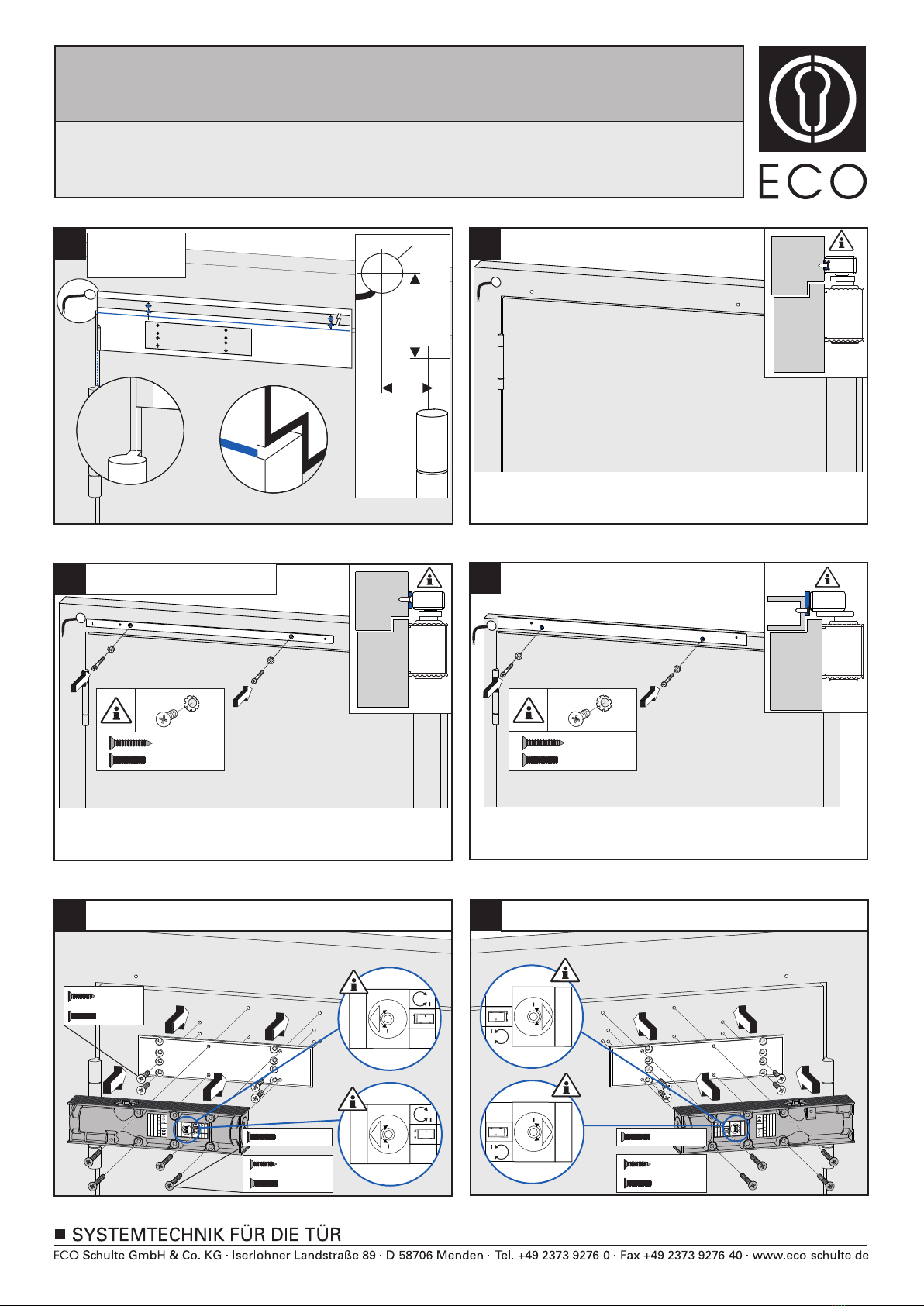
Bohrschablone anlegen und je nach Anbauvariante (Direktmontage, Montage mit Standardprofil oder Montage
mit Adaptionsprofil) Bohrlochgruppe wählen und Locher bohren. Bohrloch nach Skizze (empfohlene Maße) für
den elektrischen Anschluss bohren.
Direktmontage
2b Montage mit Standardprofil
3a
Montage mit Adaptionsprofil
1
4
5
6
7
8
9
10
Standardprofil (optional) anschrauben.
Hebelarm an den Türschließer anschrauben.
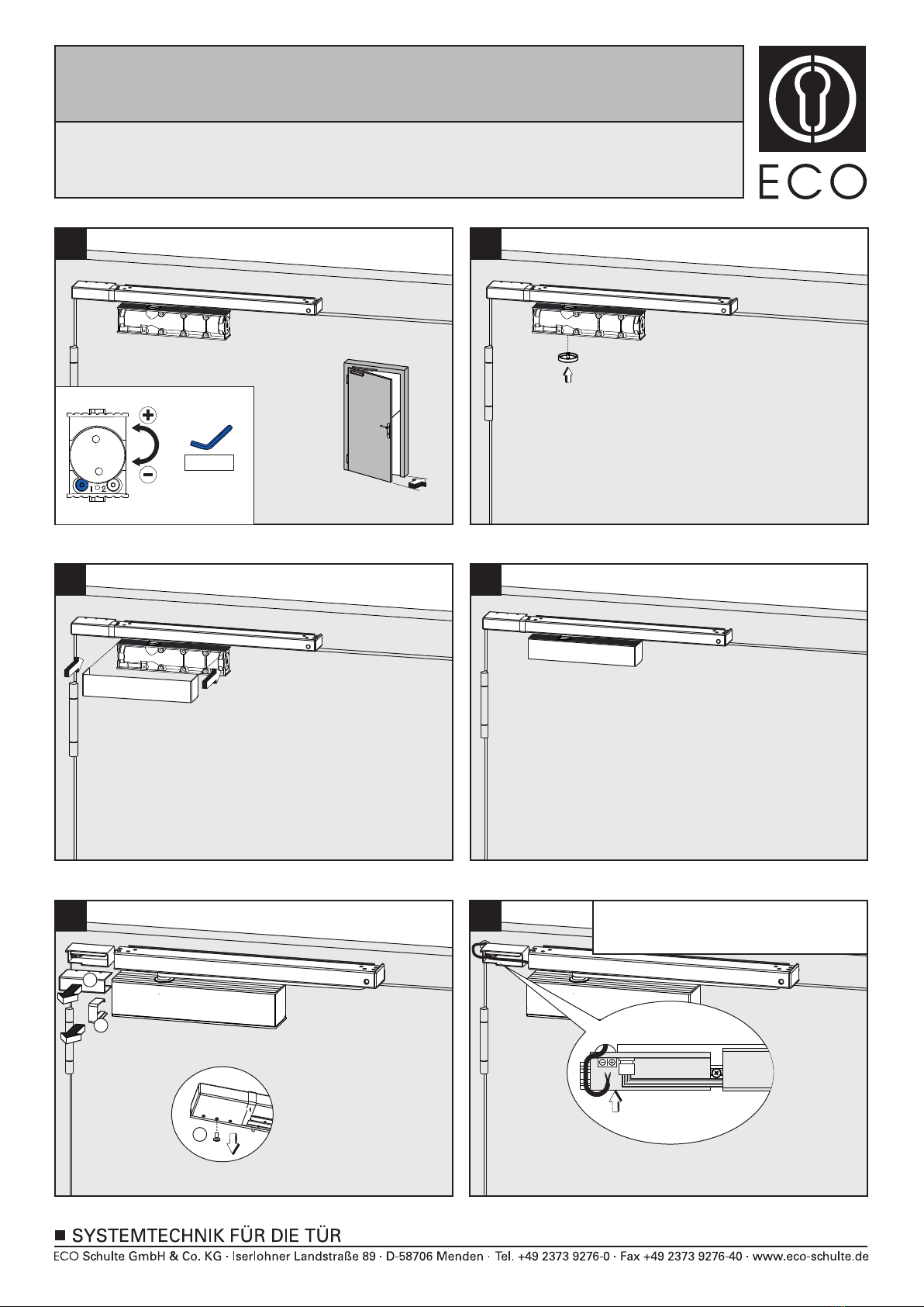
Schließgeschwindigkeitsventil schließen . Die Hebelarme Richtung Gleitschiene führen und mit den
Gleitschienen verbinden . Schließgeschwindigkeitsventil wieder öffnen, Tür schließen.
12
3
Schließgeschwindigkeit einstellen.
11
12
Montageplatte und Türschließer anschrauben. DIN links !!!
Gleitschiene an die Tür, das Standard - oder Adaptionsprofil schrauben.
Kunststoff-Clip aufsetzen.
Schließkraft einstellen.
Endschlag einstellen.
Ritzelabdeckung aufklippen.
U-Cover aufklippen.
Adaptionsprofil (optional) anschrauben.
2a
3b Montageplatte und Türschließer anschrauben. DIN rechts !!!
13 Gleitschiene mit Türschließer fertig montiert.
Im Folgenden wird die Montage für Gangflügel links gezeigt. Bei Gangflügel rechts bitte entsprechend
spiegelbildlich vorgehen.
Montageanleitung / Assembly instruction / Notice de montage
EF (24V) mit TS-41 / 31
EF (24V) with TS-41 / 31
EF (24V) avec TS-41 / 31
(DIN links / DIN rechts spiegelbildlich)
(DIN left / DIN right mirror image)
(DIN gauche / DIN droite inverser l‘illustration)
7/11
Die Feststellanlage ist für einen Türöffnungswinkel von 90° vormontiert. Der Öffnungswinkel lässt sich durch
Verschieben der Feststelleinheit in Richtung Türmitte bis auf 70° und Richtung Türbänder bis auf 130°
verstellen. Hierzu wird die Tür auf den gewünschten Feststellwinkel geöffnet und festgesetzt. Zum
Verschieben der Feststelleinheit muss die Klemmschraube gelöst werden. Die Feststelleinheit dann auf
Anschlag an das Gleitstück schieben und Klemmschraube anziehen. Beim max. Türöffnungswinkel kleiner 90°
kann das Gleitstück die Klemmschraube verdecken. In diesem Falle muss die Feststelleinheit vor dem Öffnen
und Festsetzen der Tür auf Anschlag in Richtung Türmitte nach Lösen der Klemmschraube verschoben werden.
Klemmschraube wieder festziehen und wie vorher beschrieben den gewünschten Feststellwinkel einstellen.
17
1
1
Funktionsprüfung der Feststellung durchführen!
18
Abdeckungen und Kunststoffclips einsetzen.
12
15
16
Stromzufuhr anschließen.
123
14 Verschraubungen der Stromversorgungsabdeckung lösen . Kunststoff - Clip und Abdeckung entfernen.
Abdeckungen fixieren.
Montageanleitung / Assembly instruction / Notice de montage
EF (24V) mit TS-41 / 31
EF (24V) with TS-41 / 31
EF (24V) avec TS-41 / 31
(DIN links / DIN rechts spiegelbildlich)
(DIN left / DIN right mirror image)
(DIN gauche / DIN droite inverser l‘illustration)
Elektrischer Anschluss: 24V DC, +15% / -10%

8/11
2c
2b
3a
1
4
5
6
7
8
9
10
11
12
Assembly for active leaves on the left is described below. For active leaves on the right, please proceed
accordingly.
Attach drilling template and choose corresponding drill holes depending on mounting situation (direct mounting,
mounting with standard profile or mounting with adaptor plate). Drill holes. Drill holes for electric connection
acc. to drawing (recommended dimensions).
Screw on mounting plate and door closer. DIN left !!!
Direct mounting
Mounting with standard profile
Mounting with adaptor plate
Mount the standard profile (as option).
Mount the adaptor plate (as option).
Connect arm to door closer.
Screw slide rail onto the door, the standard profile, or the adaptor plate.
Attach nylon clip.
Close the valves for closing speed . Move the arm into the direction of the slide rail and connect it to the
slide rail . Open the speed valve. Close the door.
Adjust closing speed.
Adjust closing force.
Adjust latching speed.
Clip on pinion cover.
Clip on U-Cover.
12
3
2a
3b Screw on mounting plate and door closer. DIN right !!!
13 Slide rail and door closer mounted.
Montageanleitung / Assembly instruction / Notice de montage
EF (24V) mit TS-41 / 31
EF (24V) with TS-41 / 31
EF (24V) avec TS-41 / 31
(DIN links / DIN rechts spiegelbildlich)
(DIN left / DIN right mirror image)
(DIN gauche / DIN droite inverser l‘illustration)

9/11
15
17
18
Carry out a functionality test of hold-open function and smoke detector.
Attach cover and nylon clips .
12
The slide rail with hold-open function is premounted for a door opening angle of 90°. The open angle can be
changed up to 70° by moving the hold open unit in the direction of the door middle. It can also be changed up to
130° by moving the hold open unit in the direction of the door hinges. This is achieved by opening the door until
the requested opening angle is achieved and fixing it in this position. In order to move the hold open unit, you
have to loosen the fixing screw . Move the hold-open unit till dead stop of the sliding block and tighten the
fixing screw . In case the max. door opening angle is smaller than 90°, the sliding block might cover the fixing
screw. In this case, the hold-open unit has to be moved till dead stop in direction of door middle after fixing
screw has been loosened. This has to be done before the door is opened and fixed in wished position. Tighten
fixing screw and adjust (as described above) the requested hold-open angle.
1
1
14 Loosen screws of the power supply unit . Remove nylon clip and cover .
Connect power.
123
16
Fix covers.
Montageanleitung / Assembly instruction / Notice de montage
EF (24V) mit TS-41 / 31
EF (24V) with TS-41 / 31
EF (24V) avec TS-41 / 31
(DIN links / DIN rechts spiegelbildlich)
(DIN left / DIN right mirror image)
(DIN gauche / DIN droite inverser l‘illustration)
Electrical connection: 24V DC, +15% / -10%

10/11
Ci-dessous le montage pour vantail principal gauche. Pour le montage à droite veuillez procéder en conséquence.
Positionner le gabarit de perçage et selon le cas de configuration (montage direct, montage avec profile
standard ou avec profil d’adaptation) choisir les trous adaptés puis perçer. Perçer selon le diamètre du câble
raccordement électrique.
Montage direct
Montage avec profil d’adaptation
Montage avec profil standard
Fixer le profil standard (en option).
Fixer le profil d´adaption (en option).
Fixer le bras au ferme-portes
Fixer la coulisse direct, sur le profil standard, ou sur le profil d´adaption.
Fixer le clip en plastique.
Fermer la valve du réglage de la vitesse . Positionner le bras jusqu’au patin de la glissière puis visser le bras au
patin - . Ouvrir la valve du réglage de la vitesse. Fermer les portes.
Ajuster la vitesse de fermeture.
Ajuster la force.
Ajuster l’à-coup final.
Clipser le cache de l‘axe.
Clipser le capot U en inox.
Monter la glissière et le ferme-portes.
1
23
2c
2b
3a
1
4
5
6
7
8
9
10
11
12
2a
3b
13
Fixer la plaque de montage puis le ferme-portes. DIN gauche !!!
Fixer la plaque de montage puis le ferme-portes. DIN droite !!!
Montageanleitung / Assembly instruction / Notice de montage
EF (24V) mit TS-41 / 31
EF (24V) with TS-41 / 31
EF (24V) avec TS-41 / 31
(DIN links / DIN rechts spiegelbildlich)
(DIN left / DIN right mirror image)
(DIN gauche / DIN droite inverser l‘illustration)
11/11
Le sélecteur de fermeture est pré-disposé pour un angle d’ouverture de 90°. Cet angle peut être modifié en
dévissant les vis pointeaux et en déplacant l’arrêt de 70 à 130°. De cette façon la porte peut être maintenue à
l’angle d’ouverture souhaité .
Tester le fonctionnement.
Clipser le capot ainsi que les clips plastique - .
Fixer le capot.
1
12
15
17
18
14
16
Devisser le capot du raccordement électrique . Enlever le clip plastique ainsi que le cache - .
Raccorder l‘alimentation.
3
12
Montageanleitung / Assembly instruction / Notice de montage
EF (24V) mit TS-41 / 31
EF (24V) with TS-41 / 31
EF (24V) avec TS-41 / 31
(DIN links / DIN rechts spiegelbildlich)
(DIN left / DIN right mirror image)
(DIN gauche / DIN droite inverser l‘illustration)
Raccordement électrique: 24V DC, +15% / -10%
This manual suits for next models
1
Table of contents
Languages:
Other Eco Door Opening System manuals


 User manual")


