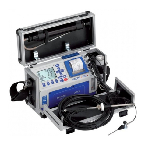
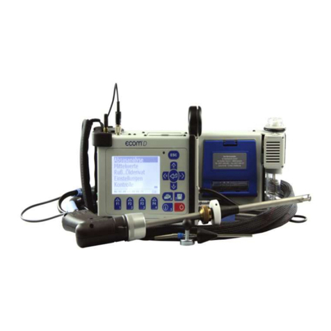
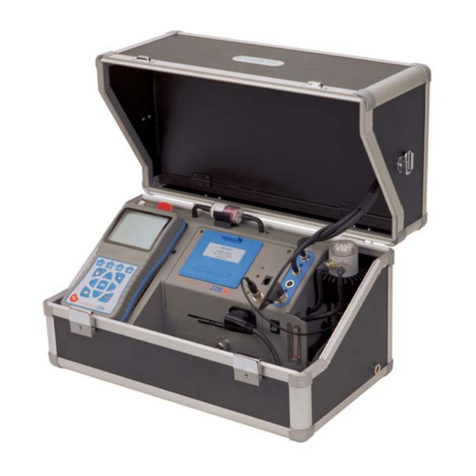
Ecom ST User manual

OPERATING INSTRUCTIONS
Version
ecom-ST 1.0 State July 2021
English

2 ecom-ST 1.0
Content
Intended Use
4
Scope of Delivery
4
General Safety Information
5
1.Device Structure
6
1.1 Components 6
1.2 Connections
8
1.3 Keypad
9
1.4 Interfaces
10
1.4.1 USB
10
1.4.2 RS485
10
1.4.3 Ethernet
13
1.5 Analog outputs (option)
16
1.6 Unheated gas sampling system
17
1.7 Heated sampling system
17
1.8 Data storage
18
2. Installation
19
2.1 Wall-mounting protective housing (option)
19
2.2 Rack installation
20
3. Starting Up
21
4. Measurement Procedure
21
4.1 Preparation 21
4.2 Flue gas analysis
22
4.3 Measurement screens
23
4.4 Draught measurement
25
4.5 CO overload protection
26
5. Control
27
6. Adjustments
29
6.1 Remote Setup 32
6.1.1 Modbus 32

ecom-ST 1.0 3
6.1.2 Time control 34
6.1.3 Configuring the Analog outputs (option) 34
7. Data Processing 36
7.1 Data logger 36
7.2 Data connection to the PC 37
7.2.1 ecom-DAS NT2 37
7.2.2 ecom-DAS 5 38
7.3 ecomModbus 38
8. Maintenance 39
8.1 Fine dust filter 39
8.2 Gas sensors 40
8.3 Calibration 41
8.4 Removal / re-installation of modules 42
8.4.1 Gas measuring module 42
8.4.2 Gas processing module 42
8.5 Probe/Tubing 43
8.6 SBK system (option) 43
Technical Data 44
Disposal 46
FAQ 46

4 ecom-ST 1.0
Intended Use
The ecom-ST is a stationary measuring instrument made by ecom
GmbH, which is intended for the semi-continuous exhaust gas
measurement at combustion systems and which is permanently installed
on site. The device is operated either by the internal time control or by
time control via Modbus. A maximum measuring time of 1 hour without
interruption is possible. Afterwards, a fresh air purging phase of at least
4 minutes with subsequent fresh air calibration (at least 1 minute) must
be carried out.
Scope of Delivery
•
ecom-ST
•
Mains power cable 2,5 m
•
Kit of consumable spares
•
Protective housing (option)

ecom-ST 1.0 5
General Safety Information
Risk of injury
Improper work on combustion engines or combustion controllers
can lead to injuries.
Work on such systems may only be carried out by specialists.
WARNING
Risk of electric shock
Live components are exposed when the housing is open. Before
opening the device, disconnect it from the power supply voltage.
WARNING
Damage to the electronics
Moisture or frost can damage the electronics. Do not store the
device in damp rooms or by temperature below 0C!
CAUTION
Damage to the sensors
Substances containing solvents damage the device's sensors.
Avoid contact with substances containing solvents!
CAUTION
Damage to electronic components
Electrostatic discharge can damage electronic components.
Before touching the inside of the housing, touch a grounded
component!
CAUTION

6 ecom-ST 1.0
1.Device Structure
1.1 Components
1
Device with
protective
housing
(option)
2
Key
NOTE
Strong electromagnetic fields can affect the function of the device. Do
not expose the device to any strong electromagnetic radiation!
2
1
NOTE
Check fine dust filter and PTFE filter regularly!
Change filter when the grey staining equals <3 on the soot dot
comparison scale!

ecom-ST 1.0 7
3
Graphic display
5
Condensation pump
7
SO2/NOxfilter
for CO sensor
4
Fresh air inlet
6
PTFE filter
8
Gas cooler with
fine dust filter
7
8
5
4
3
6

8 ecom-ST 1.0
1.2 Connections
1
USB connection
4
Analog outputs (option)
7
Measuring gas
outlet
2
Slot for multi
media card (SD)
5
Mains power
connection - max.
cable length 3 m
8
Condensation
outlet
3
Network
connection
6
Mains supply
ventilation fan
8
5
6
4
2
1
3
7

ecom-ST 1.0 9
1.3 Keypad
1
Connection LED
(only by wireless
connection)
5
ESC key
(quit/escape menu)
9
Store key
2
Info LED (for
indication of
instrument status)
6
Digital flow indi-
cation/flow meter
10
Info key (access to
control menu)
3
Battery LED (for
indication of
charging status)
7
Enter key (confirm
selection)
11
ON/OFF key
4
Function keys
(assignment shown
on display)
8
Cursor control
(up/down/right/left)
10
8
5
6
1
2
7
3
9
11
4
In input mode, the numerical function of the keys is used to enter
figures.
NOTE

10 ecom-ST 1.0
1.4 Interfaces
1.4.1 USB
The device is equipped with an USB interface. The maximum cable
length for using the interface is 2 m. The USB port can be used to
establish a connection to a PC or laptop. Data can be recorded using the
ecom PC software DAS NT 2 or DAS5.
A driver is required for communication between the device and the ecom
PC software DAS NT 2 or DAS5. PC software and USB drivers are
available free of charge on the ecom GmbH website (see
https://www.ecom.de/kundendienst/downloads/).
The following transmission parameters must be set for the two programs
on the ecom-ST ("Adjustments” /" Internal "/" USB "):
DASNT2
•
1200 Baud
•
Protocol DAS
DAS5
•
1200 to 38400 Baud (setting as in software „DAS5“)
•
Protocol Enhanced
1.4.2 RS485
An RS485 interface is available for connecting the device via Modbus
RTU. The ecom-ST supports a 2-wire topology (see figure).

ecom-ST 1.0 11
The Modbus slave address is set to 0x2 in the delivery state. The
maximum cable length is 50 m. If the ecom-ST is used as a terminal
device, a termination of 120
is provided. The termination is active on
delivery. Proceed as follows to deactivate:
1. Disconnect the device from the mains voltage.
2. Loosen the knurled screws on the front panel.
3. Open the front panel.
4. Set DIP switch 3 to OFF.
1
Knurled screw
2
Front plate
3
DIP switch
2
1
3
1

12 ecom-ST 1.0
The cable for the data connection via Modbus RTU can be connected to the
8-pin connector. The plug is then plugged into the socket on the circuit board.
The pin assignment is listed below
.
1
Pin assignment
3
8-pin socket
2
8-pin plug
4
Position at device
The following transmission parameters must be set at the ecom-ST
("Adjustments" / "Internal" / "COM module"):
•
9600 Baud (recommended adjustment)
•
Protocol Modbus RTU
4
2
1
3

ecom-ST 1.0 13
1.4.3 Ethernet
An Ethernet interface is available for connecting the device via Modbus
TCP. The ecom-ST can be integrated into a network via the LAN
connection on the front.
The following transmission parameters must be set at the ecom-ST
("Adjustments" / "Internal" / "COM-Modul"):
•
115200 Baud (recommended adjustment)
•
Protocol Modbus/TCP
Upon delivery, the ecom-ST has the IP
address "192.168.55.1". To change it,
you have to configure a PC for this
subnet. It is advisable to temporarily
configure the PC with the IP address
"192.168.55.2".
The ecom-ST has a web interface for
configuring the IP address as well as
user name and password. To connect,
enter the IP address "192.168.55.1" in
the web browser (in this example
Opera). On delivery, the user name is
"admin" and the password is
"PASSWORD".
LAN connection

14 ecom-ST 1.0
You can set the password for the administrator and for the creation of
additional users under the menu item "User".

ecom-ST 1.0 15
To adapt the network configuration, you can change the network settings
under "Network" by selecting "eth0"
→
"Configuration".

16 ecom-ST 1.0
1.5 Analog outputs (option)
The device can be equipped with 8 analog outputs (4 mA - 20 mA).
Channels 1 to 4 are available at socket 1 (lower socket) (see pin
assignment socket 1). Channels 5 to 8 are available at socket 2 (upper
socket) (see pin assignment socket 2).
Pin assignment socket 1
Pin assignment socket 2
Each channel can be assigned a measurement or calculation variable
with free scaling (see chapter “Configuring the Analog outputs”).
1
GND channel 8
4
Signal channel 7
7
GND channel 5
2
Signal channel 8
5
GND channel 6
8
Signal channel 5
3
GND channel 7
6
Signal channel 6
1
GND channel 4
4
Signal channel 3
7
GND channel 1
2
Signal channel 4
5
GND channel 2
8
Signal channel 1
3
GND channel 3
6
Signal channel 2

ecom-ST 1.0 17
1.6 Unheated gas sampling system
The ecom-ST can be equipped with a so-called NO
x
tubing. The NO
x
tubing effectively minimizes the washout losses of water-soluble gas
components like NO
2
and SO
2
. Thanks to its smooth surface and the
increased flow rate, the condensation formation and the correlated
washout impact are minimized.
1.7 Heated sampling system
By using the heated sampling system (option), the measurement of
water-soluble target substances (NO
2
and SO
2
) is possible without
washout losses. A hot gas filter integrated in the probe head protects the
device from premature contamination. The maximum exhaust gas
temperature when using the heated sampling system is 500°C.
NOTE
•Do not kink the NOxtubing!
•Do not put the NOxtubing into
water!
NOTE
•Do not kink the heated tubing!
•Do not put the heated tubing into
water!
•Clean or change the PTFE filter
regularly!
•

18 ecom-ST 1.0
1.8 Data storage
If a SD card is inserted in the device, measurements can be saved. In
order to be able to make a recording, the SD card must be inserted into
the SD card slot as shown until it clicks into place completely.
All values of a recording are saved in a csv file with the name " ST_DL-
xx.csv ". Successive files are automatically numbered from 00.
Data loss
Loss of data and damage to the data carrier are possible.
Do not pull out cards while data is being recorded!
CAUTION
NOTE
The SD card must have the following properties:
•Maximal storage capacity: 32 GB (UHC card)
•Formatting: 16-bit FAT / FAT32

ecom-ST 1.0 19
2. Installation
2.1 Wall-mounting protective housing (option)
Dimensional drawing
Fastening material is not included and must be selected on site
according to the individual circumstances.
NOTE

20 ecom-ST 1.0
1. Pre-drill the mounting holes acc. to
the dimensional drawing.
2. Depending on the wall and the
individual conditions on site, screw
the
protective
housing to the wall.
2.2 Rack installation
NOTE
For mounting, kindly consider that
the device with the
housing weighs approx. 25 kg.
Install the device in a ventilated
room only!
NOTE
6 HE must be complied with!
NOTE
Do not use the
housing
as a storage space!
Table of contents
Other Ecom Measuring Instrument manuals
Popular Measuring Instrument manuals by other brands
AEMC
AEMC 5600 user manual

BC Biomedical
BC Biomedical SA-2010S user manual
Circutor
Circutor CVM-C4 Series instruction manual

Green Energy Options
Green Energy Options Solo III Installer's guide

Sper scientific
Sper scientific 840021 instruction manual
Endress+Hauser
Endress+Hauser Gammapilot FTG20 Safety instructions
