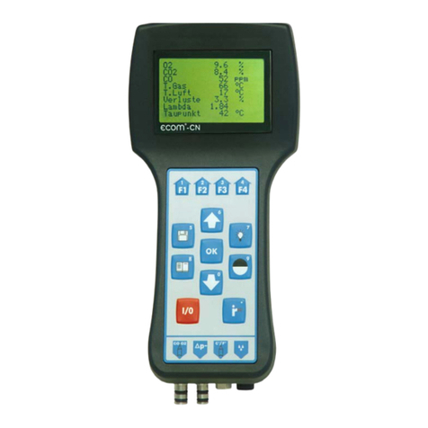
Ecom J2KN User manual

J2KN
Operation Manual
ECOM America
1628 Oakbrook Drive
Gainesville, Georgia 30507
Tel: 770.532.3280
Fax: 770.532.3620
info@ecomusa.com
www.ecomusa.com
Table of Contents

Section 1
1.1 Introduction
1.2 Analyzer & Accessories
1.3 List of Abbreviations
Section 2
2.1 Getting Started
2.2 Fuel Selection
2.3 Data Processing
2.4 Auto Zero / Auto Span
2.5 Normal Measurement Mode
2.6 Contrast
2.7 Backlight
2.8 CO Bypass
2.9 Printing
2.10 Draft & Pressure Measurement
2.11 Soot / Oil Trace Test
2.12 Adjustments
2.13 Control
2.14 Internal
Section 3
Calibration Procedure
Section 4
Performing an Emission Test
Section 5
5.1 Datalogging using the SDMM Card
5.2 Advanced DAS using the Data Interface Box
Section 6
6.1 Technical Notes

Section 1
INTRODUCTION
1.1 Introduction
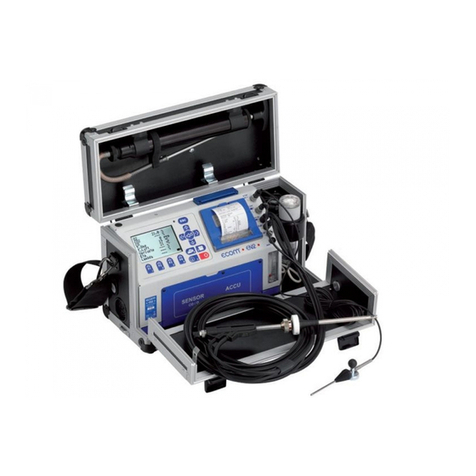
The ECOM J2KN is a portable, microprocessor controlled, electrochemical sensor based emission-
analyzer that incorporates proven technology for accurate exhaust gas analysis. The ECOM J2KN
can be fitted with up to 5 separate gas sensors.
The ECOM J2KN is suited for a variety of applications: Boiler/Burner Flue Gas Analysis; Engine
Emissions Analysis; Pollution Source Testing; and Environmental Reporting of Stack Gas
Parameters, among others. It provides measurements for O2, CO (low range 0-4,000 ppm), and / or
CO (high range 0-40,000 ppm), NO, NO2, (NOx), SO2, and Combustibles. It also measures Gas and
Ambient Temperatures, Stack Draft (pressure) and will perform a standardized smoke test. The
calculated parameters include CO2, Combustion Efficiency, Excess Air, and Losses. An on-board
printer allows hard copy printing of vital stack parameters. Datalogging is available via on-board
memory card and real time data transmission to a PC via wireless interface device.
1.2 Analyzer & Accessories
The ECOM J2KN is a portable gas analyzer that enables qualified personnel to collect accurate
emissions data for a variety of purposes, i.e. the servicing and maintenance of combustion sources
and environmental compliance. Designed as a portable analyzer for semi-continuous operation only,
the ECOM J2KN is not recommended for continuous gas emission measurement. Upon receipt of
your instrument, you should find the following components and accessory items contained within the
carry case:
ECOM J2KN analyzer, with wireless remote control.
Electronic Peltier-type gas cooler / water trap assembly, attached.
15 ft. Standard sample line.
13” Coaxial probe assembly with connections for draft, gas, temperature gas, and slot for smoke
test filter (other probe lengths available upon request)
Magnetic holster for the Remote Control
2 NOx / SO2 Filter Cartridges (p/n 79275)
2 rolls of printer paper (p/n 79285)
100 smoke paper test discs (p/n 71283)
1 package of 10 water trap filters (p/n 75316)
2 Round in-line filter (p/n 71185)
8 ft. AC power cord
Air thermocouple with 6’ cable (T-AIR connector fitted with wireless plug)
2 keys for case latches
Carry strap
User manual
Available Options
Heated sample line with probe. Custom lengths available.
SDMM Card & Card Reader – for on board datalogging
Advanced DAS software with Wireless Data Interface Box

1.3 List of Abbreviations
Listed below are some abbreviations that are used throughout this manual.
O2Oxygen
CO Carbon Monoxide
CO2Carbon Dioxide
NO Nitric Oxide
NO2Nitrogen Dioxide
NOX (NO+NO2) General term for Oxides of Nitrogen
SO2SulfurDioxide
Temp Temperature
EFF / Eta Combustion Efficiency
Batt Battery
T. Room Room Temperature
T. Gas Flue Gas Temperature
Losses Heat loss percentage
Lambda Excess Air
i.w.g. Inches of water gauge (pressure)
% v Percent by Volume
ppm Parts Per Million
mg Milligrams
mv Millivolt
V Volts
CO2Max Maximum CO2Value
NO voltage? Signal indicating that the battery voltage
on the NO sensor is low
O2 sensor? xxmV Indicates low voltage of the sensor

Section 2
2.1Getting Started
To begin analyzer operation, open the case by releasing the two latches located on the front of the
case, so that the top of the case opens upward to expose the top panel, display and keypad.
Carefully remove the hoses and cables from the top compartment of the case. Plug in the supplied
power cord to the back panel of the analyzer and to an appropriate power outlet. (The ECOM J2KN
will operate on 100 – 230 VAC) Make sure the Peltier Gas Cooler and Particulate filter assembly is
mounted properly on the top edge of the right side of the unit. The water trap bowl should be in a
vertical position on the inside of the case with the black tubing freely feeding directly into the
instrument and the electrical connector secured to the side panel. Check the tubing connection on the
bottom of the water trap bowl for cracks or tears, and be sure the top filter cap is secure.
Making the Connections
Using the standard sample line and pistol grip probe The sample line consists of a 15 foot 3 chamber
hose with connectors on each end. The connectors are sized to fit only in the correct receiver.
Connect one end of the sample line to the pistol grip probe. Please note the notched fitting on the
thermocouple connection that fits into the bottom of the pistol grip probe. This must be inserted
properly. Insert the Gas and Draft connectors into the proper receivers in the bottom of the pistol grip.
Next, connect the larger thermocouple connection to the front panel of the analyzer, then connect the
Gas and Draft lines.
Pressure Inlet T-Gas Connection
Draft Inlet Gas Inlet
Serial Number Label Power Cord &Fuse Tray
Sample Line & Probe Peltier Gas Cooler & Particulate Filter

On/Off Switch – on base unit and remote NOx /SOx
Filter
Printer / Paper Flowmeter
To turn the instrument ON, press the rocker switch marked I/O on the front right panel and press the
button marked I/O on the Remote Display until the display acknowledges power ON and reads:
Press the OK button.
If the T-Gas, T-Air or Water Trap Connections are not made, an error message will appear on the
screen indicating the source of the error.
2.2 Fuel Selection
There are 13 pre-programmed fuel selections in the ECOM J2KN. These will include Natural Gas,
Diesel Oil, Propane, Butane, Fuel Oil #2, #4, and #6, Coal, Wood (at varying moisture contents) and
others. During the Auto Zero / Span procedure, you may enter the type of fuel being burned in the
combustion process. Use the up / down arrows to select the type of fuel being burned, then press
OK.

2.3Data Processing
The next screen will ask you about data processing. There are 3 options for data processing. This
option is an option to use the internal memory. Up to 1500 "snap-shot" measurements can be stored in
the internal memory. The measurements can be transferred via RS 232 (use data cable item number
1040019) to a PC. Free rbr-software (available on website “ww.rbr.de“) enables the filing of the
recorded data. Please see the Technical Data chapter for data format information. This particular data
processing option is not typically used in North American applications, due to availability of the SDMM
Card and / or Advanced DAS software. If you are using the SDMM Card option and / or the ECOM
Advanced DAS software option, please select NO by pressing the F4 button.
If you do wish to use this option for data storage, you will need additional cables and software to program
the analyzer and to retrieve the data. Please contact ECOM for details.
2.4Auto Zero / Auto Span
Once all connections are made and the analyzer is switched on, the instrument begins its
automatic Zero / Span procedure. The analyzer should be in fresh air during this period.
During this process, the Oxygen sensor is automatically calibrated to ambient air, (20.9%)
while the other sensors are zeroed and checked for proper signal outputs. The ECOM J2KN
will count down from 60 seconds to complete the Auto Zero/Auto Span warm up period. For
best results, allow the analyzer to acclimate to the ambient temperature, then repeat the Zero
/ Span procedure.
2.5Normal Measurement Mode
After the instrument has completed its Zero / Span procedure the display will read real-time emission
values. A full screen, with all measured and calculated parameters can be viewed, or the display may
be zoomed to show only 4 parameters. Press the up/down arrow on the keypad to toggle. The
individual parameters can be set on the display by pressing F4, then using the up/down & left/right
keys to select and set the desired view.
Please note: CO2, Efficiency, Lambda, and Losses are calculated values. In order for the analyzer to
begin calculating these values, the Oxygen content has to drop below 20.5% and the T-Gas must be
at least 5 degrees higher than T-Air. When these values are not being calculated, the display will
show "“------"“in these fields.

KEYPAD FUNCTIONS
2.6Contrast
In the main menu screen, the contrast of the display can be adjusted by pressing and touching the
Contrast icons on the LCD until the desired contrast level is obtained.
Light Dark
2.7 Backlight #7 key
The ECOM J2KN is equipped with a backlit digital display for easy viewing. Simply press the
Backlight key to illuminate the display. To turn off, press again and the light will go off.
2.8 CO Bypass F3 key / #3 key
The J2KN is equipped with an automatic & manual CO Bypass to protect the CO sensor from over-
range conditions. When levels exceed the programmed CO limit, an automatic CO bypass activates a
small purge pump to divert the gas and purge the CO sensor. This function can be activated
manually, if needed, by pressing the F3 key. The display will show “----“ for the CO value when the
Bypass pump is activated. Once the CO concentration drops below 50% of the limit value, the pump
will de-activate automatically, if activated automatically, or can be turned off by pressing the F3 key
again. will activate allowing fresh-air to purge the CO-sensor. Adjusting the CO limit value will be
addressed in the Calibration section.

2.9 Printing
The easiest way to make a print-out of the measured values displayed by the ECOM J2KN, is to
simply press the F2 / #2 key. The printer will start and all measured and calculated values will be
printed on the tape. If you wish to store only one reading for later print-out, you can press the /
#5 key to store the values in short term memory. When you are ready to print, press the / . key,
then the OK key for the “Start Printout” to begin. Press the / #5 key again to clear the short
term memory.
2.10 Draft / Pressure Measurement
The ECOM J2KN is equipped with a high quality piezoresistive sensor for differential pressure
measurements that are used to measure stack draft or pressure.
To perform the draft measurement, press the Menu key to bring up the Main Menu. Select Draft
Measurement. The pump will shut off and the display will read:
Remove the draft / pressure connection from the analyzer, and press F4 to “zero” the pressure
sensor.
Re-connect to either the draft inlet or pressure inlet and allow 15 seconds for reading to stabilize and
show the exact value for draft in inches of water from 0 to +/- 40.00 inches. Press the key to
store the draft reading, then press to return to the main menu, select Gas Measurement, then
OK. To return to gas measurement function. The Draft reading is now stored in memory and will be
printed on the next print-out.
2.11 Soot – Oil Trace Test
To begin the Soot measurement, press the key to main menu. Select the Soot. Oil Trace
option, and press OK. The pump will stop. Depress the trigger on the pistol grip probe to insert the
Soot test paper disk in the slot. Release the trigger. Re-insert probe into the exhaust stack being
measured. Press the OK to begin the Soot measurement. The pump will re-start and draw 1.62 liters
of exhaust through the Soot paper. (You will see the 1.62 liters count-down on the display). When the
countdown is complete, depress the trigger on the probe to remove the Soot paper. You can now
determine the Soot level by comparing the Soot spot with the included Soot chart. The results (0.0 –
9.9) can now be entered via the keypad. This value will be stored and printed on the next test print.
Up to 3 Soot test can be entered, and the instrument will print all three and calculate the average
Soot test value.

2.12 Adjustments - Allows user to make adjustments to the calculated and measured values
The J2KN is capable of calculating emission values by changing certain options via the ECOM
J2KN’s Adjustments menu. Press the key when in the normal measurement mode to access
the Adjustments menu, then move the cursor to the relevant position and press Enter.
The following settings are possible:
Unit User-selectable units of measure:
ppm = volume concentration (parts per million)
mg/m3= mass concentration per volume
mg/kWh = mass per unit of power – O2 correctable
mg/MJ = mass per unit of heat – O2 correctable
*** FOR CALCULATION OF PPM VALUES CORRECTED TO SPECIFIC
OXYGEN CONCENTRATIONS< SELECT THE FOLLWING SCREEN:
Ref. O2 Calculation of gas concentration using reference oxygen. Activating Ref. O2
will correct toxic gas values (CO, NO, NO2) to a theoretical O2level (i.e., 3% on
boilers & 15% on reciprocating engines / turbines, is common for reporting
purposes) input through the screen below. Simply enter the value and return to
main measurement screen. Displayed values will be corrected to the desired
O2 concentration. Formula for calculation:
E ref = E meas* (21- O2ref)___
21 – O2meas

Fuel type User can changes fuel types without turning unit off
Clock set Sets the internal clock, dd:mm:yy hh:mm:ss
2.13 Control
Entering the Control screen lows user to view contact information for ECOM, millivolt reading of
sensors, operation hours, serial number, battery voltages, and software version of the analyzer. It
also allows access to calibration screens.
2.14 Internal – access through the Adjustments screen
Print Contrast – For models equipped with Thermal printers, Allows user to adjust intensity of the printout.
Not applicable to units sold in N. America.
Re-Load function – Activates battery recharge for the NiMH batteries in the Remote display. See more
detail on this feature in Section 6 – Technical Notes.
Key Beep – user can activate or de-activate the audible beep when keys are pressed.
Probe heating – the pistol grip probe has a heating element near the soot test groove to that eliminates
moisture during the soot test. This feature is automatically activated when the soot test is performed. It can
also be manually activated.
Language – English or French can be selected.
Datalogger – if using the SDMM Card for datalogging, this function is where you set the logging
frequency for the card. Times can be set for a frequency between 1 second and 255 seconds.

Section 3
Calibration Procedure
For best results, the gas concentration should be as close to the expected levels of emissions as possible.
Because each sensor is linear through a nominal range, one calibration gas concentration can be used for a
reasonably wide range of emission levels. For applications with extremely low or extremely high levels of
emissions, with respect to the sensors operation range, the sensors should be calibrated as close as
possible to desired levels to be measured. It is also recommended that, in gas mixtures that will support an
oxygen content, that a small percentage of oxygen (i.e. 2% - 5%) be in the calibration gas to aid in the
system leak check.
1. Ensure battery is fully charged. Put unit on charge the night before you plan to use analyzer to ensure
full charge of battery. Attach sample line, T-air probe, T-gas probe / sample line and power cord. Switch
on analyzer and remote display. Leave remote display in instrument cradle for calibration procedure.
2. Accept Fuel Selection with “OK” key, and select NO (F4) for Data Processing option.
3. Allow instrument to complete the 3 minute initialization and auto-zero procedure.
4. Select Gas Measurement option to perform the Air Leak test.
Air Leak Test:
1. Apply nitrogen balanced gas to analyzer through probe/sample line (you can use NO calibration gas that
is balanced in nitrogen).
2. Allow gas to flow for 3 minutes. Check that O2 reading is 0.0% (spec is +/- 0.2%). If reading other than
0.0 % , troubleshoot to source of leak and correct.
3. Do not proceed to calibrate analyzer until air leak is corrected.
To place analyzer in calibration mode perform the following steps:
1. Select “CONTROL” on main menu. Once the control screen appears, locate the battery reading (should
have at lest 6.0 volts). If battery reads anything less that 6.0 VDC consider replacing battery in near
future. Analyzer shuts off when battery reaches 5.5 VDC.
2. Swipe calibration magnet over the area near the ON/OFF switch on the remote display, located on
bottom left corner of the keypad. The calibration screen should appear on display.
3. Using the “up or down arrows” on keypad scroll cursor to the sensor that you wish to calibrate first. The
order of calibration does not matter.
Calibration of gas sensors:
With the exception of the O2 sensor, all sensors are calibrated using the same steps:
1. Connect calibration gas to analyzer using one of the following 3 set-ups:
a. (1st option) Vented flow meter configuration. Ensure sensors are not over or under pressurized by
allowing small amount of gas to out of flow meter. This prevents air from entering the system and
allows pump to control the analyzers internal pressure
b. (2nd option) Vented flow meter configuration. Ensure sensors are not over or under pressurized
by allowing small amount of gas to out of flow meter. This prevents air from entering the system
and allows pump to control the analyzers internal pressure
c. (3rd option) Use of a 15-liter gas bag or higher to ensure enough gas is present for analyzer to
stabilize. A gas bag allows analyzer to draw gas at the correct flow rate.
2. Flow calibration gas 5 minutes to sensor under test.
3. After reading has stabilized for sensor under test, press “OK” to display the input mode. Correct
calibration by inputting the value of the calibration gas being applied via the numbers on the keypad.
Confirm by pressing “OK”.
4. Remove and store calibration gas.
5. Repeat steps above for next sensor.
6. After calibration of all sensors allow the analyzer to flush with fresh air 5 minutes or until readings are
below 10 ppm for all sensors.
7. Press “menu” to back out to main menu & to select “Gas measurement” screen.
8. Press power switch to turn off analyzer.

Section 4
Basic Stack Sampling
Performing an Emission Test
Allow the analyzer to complete the 3-minute Auto Zero / Span procedure prior to beginning the emission test.
Insert the probe into the designated sampling port in the stack and allow the analyzer to draw the gas sample
for a minimum of 3 minutes to allow the readings to stabilize and the sensors to respond fully to the gas
concentration.
Please note: The entire operational procedure for performing the emission test is dependent on the
application and the objective of the emission testing. For service and maintenance applications, setting the
instrument up properly and allowing the analyzer’s reading to stabilize prior to making adjustments to the
combustion source may be sufficient. For regulatory compliance testing, please contact your local Air Quality
Board or similar agency to determine if specific test protocols are to be followed. Verification of the portable
analyzer for calibration, drift, span, interference, and other parameters, before and after an emissions
compliance test may be required by the local regulatory agency. You can ensure accurate and repeatable
results by following an established protocol. Check with the agency for any existing protocols they may
prefer or acknowledge.
ECOM America Ltd. can help you obtain acceptable protocols for your area, if required.
Additional Notes:
Variances in the analyzer’s core temperature may affect the reading and accuracy of electrochemical
sensors. Care should be taken to insure that the core temperature of the analyzer not vary by more than 15
degrees F in either direction over the testing time. It is best to allow the analyzer to acclimate to ambient
temperatures prior to start-up.
Turning the Instrument Off
When turning the instrument off, remove the probe from the stack and allow the pump to draw fresh air
through the sample line for a few minutes. Allow the CO, NO, NO2, etc. readings to return to below 15 ppm
and O2to rise above 20.0% before switching the ECOM J2KN off.
Upon being switched off, the instrument will automatically start a purging cycle that continues until the gas
values drop to zero, a process that prevents the instrument from being stored with gas in the line. The
condensate pump will run and empty any moisture that may have collected in the water trap bowl.
Disconnect the sample line and thermocouple connections and carefully store them in a suitable storage
compartment.
If the instrument is to be stored in excess of 1 month, it should be fully charged before storage and charged
again for approximately 24 hours prior to usage.

Section 5
Data Acquisition
Exhaust gas measurements can be recorded either through the SDMM card, the internal memory, or by
using the wireless data interface and Advanced DAS software.
5.1. SD Multi Media Card
The multi media card enables simple datalogging with the J2K. All datalogger records are stored in a csv file
(J2KDL-xx.csv / xx = records numbered consecutively), and, after transfer to the PC via card reader, can be
opened with Excel.
The SDMM Card function will operate with all J2K instruments containing software version 1.4 or higher.
SDMM Card should be 32 MB minimum, formatted to 16 bit FAT. ECOM sells the SDMM Card and Card
reader, (J2K Multi-media card & card reader kit, Part Number rbr69865). The following brands have also
been proven to function properly:
SD cards or MM cards -SanDisk or Infinion
PC card reader - Belkin or SanDisk
Data logging Instructions
After having started the J2KN and allowed the analyzer to perform 3 minute initialization, you may set up the
data logging function.
Insert MM card in slot on top of J2KN remote. Remote will respond with message that MM card is
compatible.
From the Main Menu Screen, scroll to Adjustments, then select Internal, then select datalogger. Use
keypad on the remote to enter the frequency of data collection between 1 second and 255 seconds. Press
OK. (Center button).
Press Menu button (bottom left on keypad) 2 times to return to Main Menu Screen.
Select Data processing & press OK. Select datalogger, press OK. The screen will display start dl? Press
Yes. The data save icon will begin to flash in the upper right corner of the display.
Return to Main Menu Screen by pressing the Menu button once. Select Gas Analysis to view real time
readings from the analyzer.
To stop the data logging session, press Menu, select Data Processing, and then select datalogger.
Screen will display finish dl?, Press Yes.
To view the recorded data, remove the MM Card from the J2K Remote. Follow the instructions for connecting
and installing the card reader to your PC. Insert the MM Card into the card reader. You may now view the
contents of the MM card on your PC. Open with Excel. The files will be listed as J2KDL-xx.csv. The xx will be
the sequential order of the recordings to the MM card since last format / erasure, i.e J2KDL-00.csv, J2KDL-
01.csv, J2KDL-02.csv, would be the first 3 recording on the card.

The data collected on the J2K with Multi Media Card will open in a spreadsheet with the recorded on
calculated values displayed in the following format.
Column Description Range/Comment/Example
A Date DD.MM.YYYY 13:02:2006 (February 13, 2006)
B Time HH:MM:SS 09:36:54 (9:36:54 AM)
C O2 in vol.% 0.0 – 21.0
D CO in ppm 0 - 4000
E NO in ppm 0 – 4000 Standard, 0.0 – 300.0 Low NOx
F NO2 in ppm 0 – 500 Standard, 0.0-50.0 Low NOx
G SO2 in ppm 0 – 5000 (0 if SO2 sensor not installed)
H CO w/ O2 correction applied 0.0-20.0 %
I NO w/ O2 correction applied 0.0-20.0 %
J NO2 w/ O2 correction applied 0.0-20.0 %
K NOX w/ O2 correction applied 0.0-20.0 %
L SO2 w/ O2 correction applied 0.0-20.0 % (0 if SO2 sensor not installed)
M T.Gas in °C or °F Exhaust Gas temperature w/ probe
N T.Air in °C or °F Ambient Air temperature at instrument
O Draft in “ H2O 0.0 – 40.0 inches water gage
P CO2 in vol.% 0.0 – 25.0
Q Efficiency in % 0.0 – 100.0
R Losses in % 0.0 – 100.0
S Excess air (Lambda) 1.00 = 0.00% excess air, 1.20 = 20% excess air
T Dew point in °C or °F
U Poisoning index
V O2 (gas channel check) in vol.% 0.0 – 21.0
W CO (gas channel check) in ppm related to 0,0 vol.% O2
X CO (gas channel check) in ppm Measured value
Y O2 (check if O2 mixed) in vol.% 0.0 – 21.0
Z T. Boiler 0 - 999
AA T. Sensor (internal sensor temp) 0 – 99 F
AB O2 Correction 0.0 – 21.0 (programmed by user)
AC Unit of measure 0=ppm; 1=mg/m3; 2=mg/kWh; 3=mg/MJ
AD O2 Correction N= O2 correction value.
AE Fuel type number Refer to instrument fuel choices
AF Fuel type text Refer to instrument fuel choices
AG Soot Test # 1 value 0.0 – 9.9
AH Soot Test # 2 value 0.0 – 9.9
AI Soot Test # 3 value 0.0 – 9.9
AJ Oil trace 0=no; 1=yes;

5.2 Advanced DAS software using the Data Interface Box
Kit contents:
ECOM Data Interface Box
AC Power Adapter
(2) 20’ RJ45 telephone cables
Advanced DAS Software disk
USB cable
Software installation help guide
Please note: Advanced DAS software should be installed on the PC prior to synchronizing the
ECOM Data Interface Box with the analyzer and PC.
Set-up directions:
The Data Interface Box must be synchronized with the corresponding J2K / J2KN for wireless
operation the first time it is used with the analyzer.
Please follow these steps:
1. Switch on the analyzer, and allow it to complete the 3 minute auto-zero.
2. Using one of the cables, connect the J2K base module port to the base module port on
the back of the interface box.
3. Using the other cable, connect the J2K Remote Control port to the remote control port on
the back of the data interface box.
4. Connect the USB cable to the Data Interface Box and to the PC.
5. Connect the AC power adapter to the Data Interface Box and move switch to the ON
position. You should see the RED power light on the front.
6. Boot up the PC and start the Advanced DAS program. You should see real-time values
from the analyzer.
7. Disconnect the telephone cables from the base module, remote control and data interface
box.
8. All future operation of the J2K/J2KN data interface box can be performed without the use
of the telephone cables.

Section 6
Technical Notes
Power Supply & Battery Charging
The internal battery of the J2K base is a 6 V; 7,2 Ah lead acid battery. Full capacity is achieved with
a 8-12 hour charge and will operate the analyzer for up to 6 hours, under most conditions. In order
for the Peltier Gas Cooler to work at maximum efficiency, it is necessary to operate on 120 VAC
power. The analyzer may be stored while connected to AC current. Once the internal battery is fully
charged, it will switch to a trickle charge to maintain maximum capacity.
The batteries in both the base and the remote should be recharged when the instrument displays a
"Low Battery" warning. Battery voltages can be checked by viewing the "CONTROL" screen on the
remote display. The low battery warning in the base unit is activated when the charge drops below 6
V. At 5.8 V, the analyzer will not operate on the batteries, but can be powered by AC power. The
low battery warning in the remote unit is activated when the charge drops below 4 V. At 3.8 V, the
remote will not operate on the batteries, and must be recharged in the base. However, it will operate
in the base unit cradle, while it is re-charging.
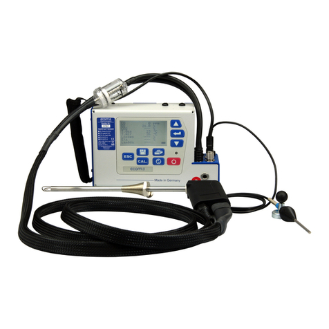
The control module of the ecom-J2K is powered by 3 nickel-metal-hydride batteries, (type AA).
When these batteries need charging, they can be recharged by docking the control module to the
base unit.
2 different charging options are available:
(Adjustments / Internal / Reloading function / <OK>):
1. Recharging function ON (<F1> = YES):
- batteries slowly and deeply recharged
- recommended if analyzer used frequently
2. Recharging function OFF (<F4> = NO):
- provides quick charge
- recommended if analyzer used infrequently,
or for emergency situations
Never use alkaline batteries to operate the control module of the ecom-J2K!

Peltier Gas Cooler / Water Trap Assembly
Proper Sample Conditioning is key to accurate and reliable flue gas measurements. The ECOM J2K employs
a high capacity Thermoelectric Peltier Gas Cooler and Condensate Trap to ensure proper conditioning of the
flue gas sample. The flue gas is drawn from the stack, through the probe and sample line where it enters the
gas cooler assembly. The gas travels thru a surface coated metal body with good thermal conductivity. The
gas radiates its heat to this metal body. A PELTIER element (semiconductor cooling element supplied by a
continuous current) creates a heat transfer from WARM to COLD, drains the heat of the metal body, and
conveys it to a fan cooled heat sink.
The condensation created by the heat loss of the gas drops in to a bowl and is pumped out automatically by
the peristaltic pump, which is controlled by moisture sensing contacts inside the water trap bowl.
The J2K's high capacity internal pump flows the sample gas at a rate which does not allow sufficient contact
time of the gas with the condensate, eliminating any absorption or "wash out" of the NO2 or SO2 gas. At the
cooler outlet, the gas has a temperature of about. 5 °C with a relative humidity of < 50%, corresponding to
what is considered a "dry gas sample."
Filter Maintenance
The small round fiber filter, part number 75316, found in the top of the Peltier cooler assembly, should be
inspected and changed prior to each use. To change this filter, unscrew the clear glass cover. Replace filter
and replace glass cover. Do not over tighten.
NOx / Sox Filter Cartridge
This filter, part number 71292, is used to scrub nitrogen and sulfur compounds from the gas sample going to
the CO sensor only. This eliminates any cross interference on the CO sensor, providing more accurate CO
readings. This filter material will be purple when new, then will change to a brownish / black color, and finally
some of the beads will turn ashy-white, when the filter needs to be replaced.

Radio communication between base unit & remote
The information exchange between the remote control and base module is via
radio transmission (868 MHz) with coverage of 150 feet, dependent on outside RFI
/ EMI. The strength of the radio signal is indicated by a bar on the bottom right side
of the main menu screen.
If there is interruption of the radio signal, an error message is displayed. Move
closer to the base unit to re-establish communication. If this is not possible, a RJ45
cable can be used. (Connection between socket DATA on control unit and socket
DATA on base module).
If the base unit is switched off with the remote control still powered, the display will
show an error message to place the remote control into its docking station. Press
<ESC>, place the remote into the docking station, and then switch it off.

“Air free CO measurement”
The J2KN can be used to check CO levels in the gas stream, relative to a 0% O2 concentration. To
view this screen, press the UP or DOWN arrow key in the Gas measurement mode. A screen
similar to the one below will be seen.
The calculated value shown on the line
CO 0% corresponds to the measured
CO concentration if the oxygen
content was 0% in the gas stream.
To store the value, press the
key <Memory> (disk symbol) to store
the result in the intermediate memory.
To printout the values, press <F2>.
Oxygen check
The same type of measurement can be made for only measuring Oxygen. Access this screen by
again pressing the UP or Down key. A screen similar to the one below will be seen.
To store the value, press the
key <Memory> (disk symbol) to store
the result in the intermediate memory.
To printout the values, press <F2>.
O2 17.5
%
CO 0% ppm 738
CO 123
CO measurement 12:15:53
25.11.03
Oxygen Test
O2 19.5
Oxygen check 25.11.03
Stored CO
Table of contents
Other Ecom Measuring Instrument manuals
Popular Measuring Instrument manuals by other brands

PRÜFTECHNIK
PRÜFTECHNIK FLUKE VIB 6.12 Series Additional Instructions for Installation and Operation
Emerson
Emerson PENBERTHY LC Series Installation, operation and maintenance instructions
R.M. Young
R.M. Young 05305L instructions
PASCO
PASCO OS-7053 manual

PCE Health and Fitness
PCE Health and Fitness DRH E Technical description
steute
steute RF LDS SPOT-ST-NET Mounting and wiring instructions
