manuals.online logo
Brands
  1. Home
  2. •
  3. Brands
  4. •
  5. EDAN
  6. •
  7. Medical Equipment
  8. •
  9. EDAN SD2 User manual

EDAN SD2 User manual

SD2 Ultrasonic Pocket Doppler User Manual
About this Manual
P/N: 01.54.459245
MPN: 01.54.459245010
Release Date:Mar. 2022
© Copyright EDAN INSTRUMENTS, INC. 2022. All rights reserved.
Statement
This manualwill help you understand the operation and maintenance of the product better. It is reminded
that the product shall be used strictly complying with this manual. User’s operation failing to comply with
this manual may result in malfunction or accident for which Edan Instruments, Inc. (hereinafter called
EDAN)cannot be held liable.
EDAN owns the copyrights of this manual. Without prior written consent of EDAN, any materials
contained inthis manual shall not be photocopied, reproduced or translated intoother languages.
Materialsprotected by the copyright law, including but not limited to confidential information such as
technical information and patent informationare contained in this manual, the user shall not disclose such
information to any irrelevant third party.
The user shall understand that nothing in this manual grants him, expressly or implicitly, any right or
license to use any of the intellectualproperties of EDAN.
EDAN holds the rights to modify, update, and ultimately explain this manual.
Responsibility of the Manufacturer
EDAN only considers itself responsible for any effect on safety, reliability and performance of the
equipment if:
Assembly operations, extensions, re-adjustments, modifications or repairs are carried out by persons
authorized by EDAN, and
The electrical installation of the relevant room complies with national standards, and
The instrument is used in accordance with the instructions for use.
EDAN will make available on request circuit diagrams, component part lists, descriptions, calibration
instructions, or other information that will assist service personnel to repair those parts of the equipment
that are designated by EDAN as repairable by service personnel.
Product Information
Product Name:Ultrasonic Pocket Doppler
Model:SD2, SD2Pro, SD2 Plus, SD2 Lite, SD2 Basic
Terms Used in this Manual
This guide is designed to give key concepts on safety precautions.
WARNING
AWARNING label advises against certain actions or situations that could result in personal injury or
death.
CAUTION
A CAUTIONlabel advises against actions or situations that could damage equipment, produce inaccurate
data, or invalidate a procedure.
NOTE
A NOTE provides useful information regarding a function or a procedure.
⚫Safety Precautions
CAUTION
Federal (U.S.) Law restricts this device to sale by or on the order of a physician
NOTE:
This user manual is written to cover the maximum configuration. Therefore, your model may or
may not have some of the parameters and functions described, depending on what you have
ordered.
This unit is internally powered equipment, and it is an IEC/EN 60601-1 Type BF applied part.
Type BF protection means that the connection between the equipment and personnel complies
with permitted leakage currents and dielectric strength of IEC/EN 60601-1.
WARNING and CAUTION messages must be observed. To avoid the possibility of injury,
observe the following precautions during the operation of the device.
WARNING
1 It is to be used by health care professionals and patients on the order of a physician.
2 Before the SD2 is prescribed for home use, the user (patient) must be instructed/trained in
proper use of the equipment.
3 Home fetal heart rate detection has not been shown to prevent the onset of preterm labor nor
will it prevent the occurrence of preterm birth.
4 The Doppler is a tool to aid the user in hospitals, clinics or at home and should not be used in
place of normal fetal detection. It is not intended for treatment or use during labor and delivery.
5 Placement of the ultrasound transducer on the abdomen is critical to obtaining the fetal heart
beat as opposed to maternal heart beat or other abdominal noise. The user should be trained
in proper placement techniques either through acceptable Ob/Gyn training and individual
state accreditation, or as being prescribed by such a trained clinician and trained in device
placement.
6 This device is not explosion-proof and cannot be used in the presence of flammable
anesthetics.
7 Magnetic and electrical fields are capable of interfering with the proper performance of the
device. For this reason, make sure that all external devices operated in the vicinity of this
device comply with the relevant EMC requirements. X-ray equipment and magnetic resonance
imaging (MRI) devices can emit high levels of electromagnetic radiation.
8 We recommend that exposure to ultrasound should be kept as low as reasonably achievable.
This is considered to be good practice and should be observed at all time.
9 Do not use the device with HF surgical equipmentand do not use it in an MRI environment.
10 The device is not protected against defibrillation.
11 SHOCK HAZARD - Do not attempt to replace batteriesor connect or disconnect a power cord
with wet hands.
12 The device should not be used adjacent to or stacked with other equipment and that if
adjacent or stacked use is necessary, the device should be observed to verify normal
operation in the configuration in which it will be used.
13 Please ensure the light of SpO2 sensor is fully covered by the finger pulp. Please check the
application site every 0.5 to 1 hour. If the skin quality changes, please change another site
14 The medical electrical equipment needs to be installed and put into service according to the
EMC Information provided in this user manual.
15 Portable and mobile RF communications equipment can affect medical electrical equipment;
refer to section Recommended Separation Distances.
16 Do not service or maintain the device or any accessory which is in use with a patient.
CAUTION
1 Refer servicing to qualified personnel.
2 Keep the device in a clean environment and avoid vibration during storage.
3 Do not sterilize the Doppler.
4 Only use SpO2 sensor approved by the manufacturer. Using other SpO2 sensors may
compromise device functionality.
5 Electromagnetic Interference - Ensure that the environment in which the device is operated is
not subject to any source of strong electromagnetic emissions, such as radio transmitters,
mobile telephones, etc.
6 The device and accessories are to be disposed of according to local regulations after their
useful lives. Alternatively, they can be returned to the dealer or the manufacturer for recycling
or proper disposal. Batteries are hazardous waste. Refer to IEC61429 for standard disposal
when necessary.Do NOT dispose them together with house-hold garbage.
7 The loss of pulse signal may occur when the patient has poor peripheral perfusion, and the
screen will display “---”. When there's measurement beyond range, invalid measurement or no
measurement value, it will display “---”.
⚫Introduction
Intended Use/Indications for Use
The SD2 detects fetal heart rate (FHR), maternal oxygen saturation (SpO2) and pulse rate (PR) for
pregnant women. The product is only intended for use in hospitals, clinics or at home by health care
professionals with relevant expertise and pregnant women who have been trained (by studying
instructional videos or product manuals) or have received professional guidance.
Features
You may not have all of these features, depending on the model purchased.
Model
Function
SD2
SD2 Pro
SD2 Plus
SD2 Lite
SD2 Basic
Curve Display
√
√
√
O
O
FHR
√
√
√
√
√
PR
√
√
√
╳
√
SpO2
O
√
O
╳
O
Bluetooth +APP
O
√
√
╳
O
Variable Frequency
√
√
√
√
√
AA Alkaline Batteries
√
√
√
√
√
Charging Function
O
O
O
O
O
NOTE: √ = Standard O = Optional ╳= Not Available
Interface:
There are three display modes. Double click the power touch key to switch the display modes. The
displayed results of SpO2and PR are updatedevery second.
Numeric Display Interface
FHR Curve Display Interface
SpO2 Wave Display Interface
Appearance(Above pictures are just for reference)
Item
Description
1
Fetal heart icon
Indicates fetal heart beat and flickers to the fetal heart beat.
2
Perfusion bar
Indicates pulse beat
2
FHR numeric
Displays fetal heart rate within the range from 30
bpm to 240 bpm.
PR numeric
Displays pulse rate within the range from 30 bpm to
240 bpm
SpO2 numeric
Displays SpO2 within the range from 70% to 100%
Volume
numeric
Volume numeric is displayed in the center of the
screen, and ranges from level 0 to 7.
3
Battery
indicator
Displayed on the bottom left corner of the
screen and there are five degrees. When the
battery indicator is empty and keeps
flickering, it indicates that the battery level is
extremely low and battery needs to be
replaced or charged.
4
Fetal heart
signal quality
indicator
Displayed on the bottom right corner of the
screen and there are three levels,
representing poor, acceptable and good
signal quality.
5
Volume
increase touch
key
Touch the key to decrease volume.
6
Volume
decrease touch
key
Touch the key to increase volume.
7
Ultrasound
frequency
2MHz,
3MHz
Indicates the current ultrasound frequency. Touch the
volume increase and decrease touch keys simultaneously to
switch the frequency.
2 MHz:used for more than 12-week gestation
3 MHz:used for more than 9-week gestation
8
Power touch
key
Touch this key for a little while to switch it on or off;
⚫Basic Operation
NOTE:
To ensure that the Doppler works properly, please read this chapter and ChapterSafety Precautions
before operation; follow the steps when connecting all the components.
Opening the Package and Checking
Open the package; take out the Doppler and accessories carefully. Keep the package for possible future
transportation or storage. Check the components according to the packing list.
◆Check for any mechanical damage.
◆Check all the cables and accessories.
If there is any problem, contact us or your local distributor immediately.
Installing the Battery
a) Remove the battery compartment cover.
b) Insert the battery into the compartment carefully. Ensure its anode and cathode terminals are aligned
with the anode and cathode marks on the compartment.
c) Install the compartment cover.
Recommended Battery Type:
AA Alkaline battery(AA,LR6,1.5 V);AA Rechargeable NI-MH battery(AA, Ni-MH, 1.2 V)
Charging the NI-MH Batteries
When battery level is low,take the batteries out from the main unit, and charge them with a NI-MH battery
charger. The specifications of the provided battery charger are as below. You can also purchase a battery
charger that meets the following specifications:
Output:1.2V-500mA*4AA 500mA*2AAA
Battery Capacity:500mAh~3000mAh
NOTE:
Ifrechargeable NI-MH battery is configured,
1 Please fully charge the battery after each use of the Doppler to ensure sufficient power during
subsequent use.
2 Please charge the battery after each transportation or storage.
WARNING
1 Turn off the Doppler before removing or replacing the battery.
2 Replace alkaline batteries with those of identical specifications provided by the manufacturer
or purchased locally. SeeProduct Specificationsfor details about battery specifications.
3 If the batteries have been inserted incorrectly, the Doppler will not function or it will be
damaged.
4 Keep battery away from children. If swallowed, consult a physician at once.
5 Do not disassemble or short-circuit batteries.
6 Do not recharge alkaline batteries.
7 Do not dispose of batteries in fire or water.
8 Do not mix with used or other battery type (such as alkaline with carbon zinc).
9 Do not solder the batteries directly.
10 Do not over-discharge batteries.
11 Do not allow metal objects to contact the battery terminals.
12 To install or remove batteries, follow the equipment manufacturer’s instructions.
13 Remove the battery and store it at a cool and dry environment if the Doppler is not used for a
long time.Do not keep batteries at temperature of 45° C or above, or at humidity of 75% or
above. For rechargeable NI-MH batteries, please charge them at least once every 3 months.
14 If rechargeable batteries are used, charge them fully before initial use by using the method
introduced in this manual.
15 The rechargeable NI-MH batteries should be charged by using the qualified dedicated
adapterthat conforms to requirements of IEC 60601-1.
16 If the time that the Doppler using rechargeable NI-MH batteries becomes much shorter than
usual, the battery life is at an end. Replace the batterieswith new ones.
Switching On
Touch the power touch key for about 1second when the Doppler is off, and the Doppler will display the
switching on interface before switching to display the test interface.
Switching Off
Touch the power touch key for about 1second when the Doppler is on, and the Doppler will be switched
off.If the Doppler is not in operation or no signal is received for 1minute, the Doppler will be switched off
automatically.
⚫FHR Detection
SD2 is designed to detect the fetal heartbeat from the 10th week of gestation.
Before applying the Doppler to inspect FHR, you should always check whether the Doppler is in good
condition and whether there is evident damage that might affect patient’s safety and the device’s
function.If evident damage is found, stop using it at once and replace it with a good one.
Procedures to Detect FHR:
a) Have the patient lie on her back.
b) Apply appropriate amount of coupling gel to the ultrasonic transducer head of the
Doppler and switch on the Doppler.
c) Palpate the patient’s abdomen gently to confirm the fetus’s position.
d) Place the Doppler on the patient’s abdomen, and move it around the fetus’s position
or tilt it until a clear and rhythmic heart sound is heard and FHR numeric is stably
displayed.
Note:
1 Do not mistake the maternal heart rate for fetal heart rate.The fetal pulse should be
different from the maternal pulse, which can be measured at the wrist or neck
2 Do not wear gloves to touch the keys. If there's water and coupling gel on the fingers, please clean
them first or the touching effect will be influenced.
How to Find the Best FH Signal:
1) The easiest way: take the position the doctor last detected for FHR as a reference and move the
Doppler around the position slowly until the best FH signal is found.
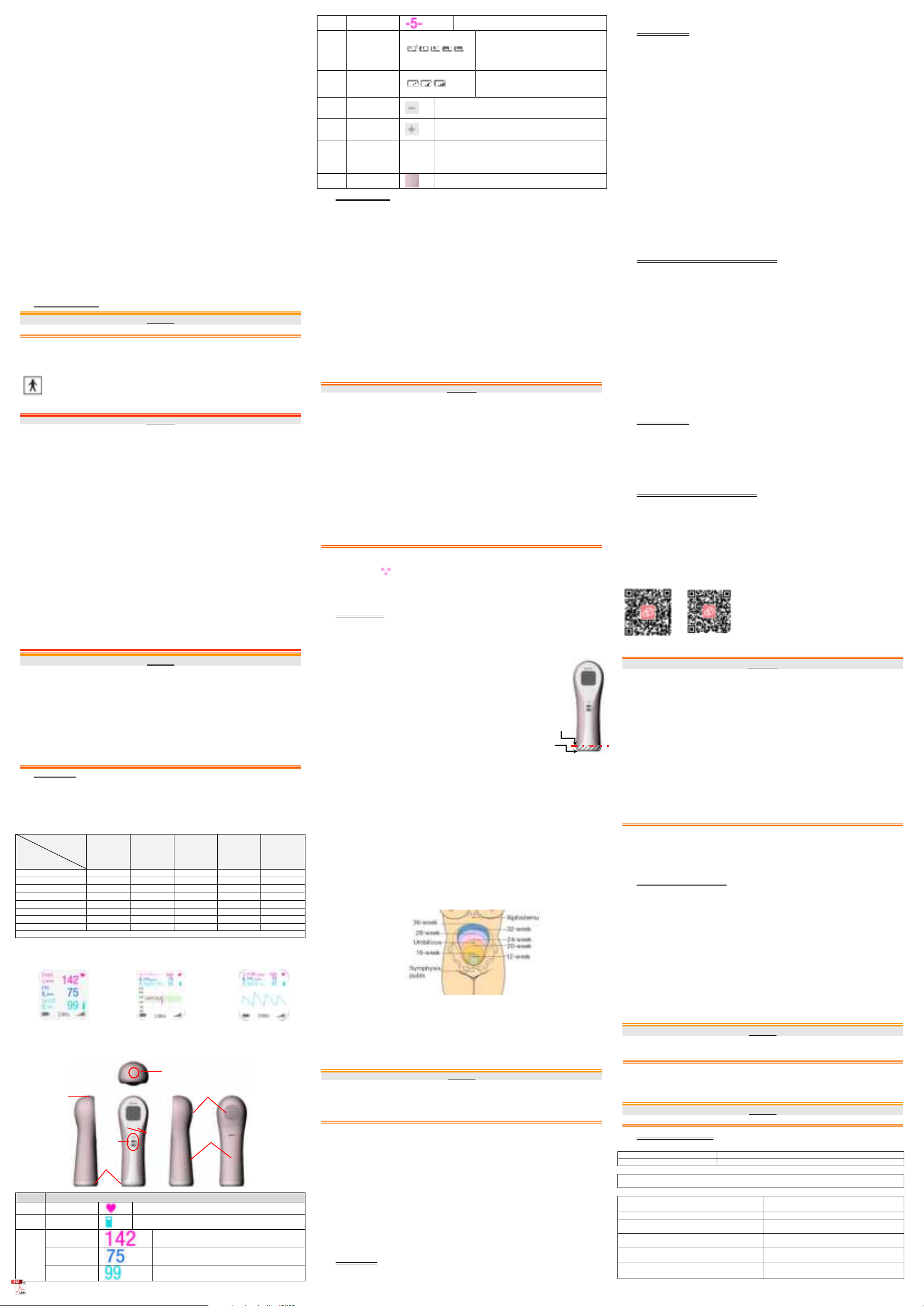
2) The fetal heart position may change as the fetus moves inside the uterus. You can confirm the fetal
position first according to the position of the uterus fundus in different gestational weeks.
➢At the end of the 12-week gestation, the uterus fundus is about 2-3 fingers’ breadth (about 3-4.5
cm) above the symphysis pubis.
➢At the end of the 16-week gestation, the uterus fundus is in the middle between the navel and
the symphysis pubis.
➢At the end of the 20-week gestation, the uterus fundus is about 1 finger’s breadth (about 1.5 cm)
below the navel.
➢At the end of the 24-week gestation, the uterus fundus is about 1 finger’s breadth (about 1.5 cm)
above the navel.
➢At the end of the 28-week gestation, the uterus fundus is about 3 fingers’breadth (about 4.5 cm)
above the navel.
➢At the end of the 32-week gestation, the uterus fundus is in the middle between the navel and
the xiphisternum.
➢At the end of the 36-week gestation, the uterus fundus is about 2 fingers’ breadth (about 3 cm)
below the xiphisternum.
The clearest and loudest fetal heart sound is generally obtained when the Doppler is placed on the
fetus’s back. Fetal movement is usually the movement of fetal limbs. So, if frequent fetal movement
occurs at the right side of the abdomen, the fetus’s back is probablyat the left sideand vice versa.You can
find the fetus’s back according to fetal movement’s position.
If the fetus is in cephalic delivery position, the fetal heart is either on the right side or on the left side
below the navel; if the fetus is in breech delivery position, the fetal heart is either on the right side or on
the left side above the navel.
Steps to Find Fetal Heart:
Have the patient lie on back and relax >> confirm fetal position by hand >> apply coupling gel to the
Doppler>> place the Doppler on patient’s abdomen and start looking for the fetal heart >> the fetal heart
is found when the Doppler gives out a continuing thumping sound “boom-boom-boom”.
CAUTION
1 The Doppler’s degree of protection against harmful ingress of water is IP22. Do not immerse it
in water.
2 The Doppler is delicate and sensitive. Please handle it with care and try to avoid dropping on to
the ground or any hard surfaces. Any damage caused by dropping is not covered by the
warranty.
3 Keep the coupling gel away from children. If swallowed, consult a physician at once.
Note:
1 The best quality of fetal heart signal is obtained only when the Doppler is placed in the best
detection position.
2 Do not place the Doppler near positions where placental sound or umbilical blood flow sound
is loud.
3 If the fetus is in the cephalic position and the mother is supine, the clearest heart sound will
normally be found on the midline below the navel. During detection, the pregnant woman’s
prolonged lying in the supine position should be avoided to reduce the possibility of supine
hypotension. Putting a pillow or cushion under the patient’s head or feet can be of help.
4 It is not possible to obtain accurate FHR unless a clear fetal heart signal is detected. If the
calculated FHR is not in accordance with the beat of the fetal heart sound, the fetal heart
sound auscultation result shall prevail.
5 Whether the fetal heart sound can be obtained or not is related to the skill and qualification of
the operator.
6 If the fetal heart sound cannot be found for a long time, it is necessary make use of other
equipment.
7 When applied to the patient, the Doppler may warm slightly (less than 2°C (35.6°F) above
ambient temperature). When NOT applied, the Doppler may slightly (less than 5°C (41°F)
above ambient temperature).
⚫SOV Prompt
When detecting fetal heart rate, there are possibilities that maternal HR signal is mistaken for FHR signal.
The SOV function can reduce these possibilities.Detect FHR and PR at the same time. When FHR and
PR signals overlap, SD2 will issue a sound. At this time, examine the patient or reposition the probe until
fetal heart signal is found.
⚫SpO2 Detection
SpO2 Plethysmogram measurement is employed to determine the oxygen saturation of hemoglobin in
the arterial blood. The SpO2 numeric shows the percentage of hemoglobin molecules which have
combined with oxygen molecules to form oxyhemoglobin. The SpO2/PLETH parameter can also provide
a pulse rate signal and a plethysmogram wave.
NOTE:
1 The device is calibrated to display functional oxygen saturation.
2 The monitor does not have specific SpO2 calibration baselines.
3 SpO2 waveform is not proportional to the pulse volume.
4 A Functional tester or simulator cannot be used to assess the SpO2accuracy. However, it can
be used to test the accuracy of a particular calibration curve duplicated by the device, and it
turns out the calibration curve meetsthe accuracy.
Inaccurate measurements can be caused but not limited by:
●Incorrect device application
●high levels of ambient light sources, such as surgical lights (especially those with a xenon light
source), bilirubin lamps, fluorescent lights, infrared heating lamps, and direct sunlight
●failure to cover the sensor with fingerin high levels of ambient light conditions
●dysfunctional hemoglobins
●low peripheral perfusion
●excessive or violent patient movement
●venous pulsations
●intravascular dyes, such as indocyanine green or methylene blue
●externally applied coloring agents (nail polish, dye, pigmented cream)
●defibrillation
●placement of the device on an extremity with a blood pressure cuff, arterial catheter, or intravascular
line
●electromagnetic interference
●Low perfusion
Lossofpulse signal can occur for the following reasons:
●a blood pressure cuff is inflated on the same extremity as the one with the device attached
●there is arterial occlusion proximal to the device
●low peripheral perfusion
⚫Assessing the Validity of a SpO2 Reading
You can check the quality of the pleth wave and the stability of the SpO2 values to assess whether the
sensor functions properly and whether the SpO2 readings are valid. Always use these two indications
simultaneously to assess the validity of a SpO2 reading.
NOTE:
1 The SpO2accuracy has been validated in human studies against arterial blood sample
reference measured with a CO-oximeter. Pulse oximeter measurements are statistically
distributed, only about two-thirds of the measurements can be expected to fall within the
specified accuracy compared to CO-oximeter measurements. The volunteer population in the
studies composed of local healthy men and women from age 19 to 37, with variations of skin
pigmentations. The SpO2accuracy is as follows: ±2% for 90%-100% and ±4% for 70%-90%.
2 The pulse rate accuracy is obtained by comparison to the pulse rate generated with an arterial
oxygen simulator (also an electronic pulse simulator).
3 Generally, the quality of the SpO2 pleth wave reflects the quality of the light signals obtained by
the sensor. A wave of poor quality manifests a decline of the signal validity. On the other hand,
the stability of the SpO2 values also reflects the signal quality. Different from varying SpO2
readings caused by physiological factors, unstable SpO2 readings are resulted from the sensor’s
receiving signals with interference. The problems mentioned above may be caused by patient
movement, wrong sensor placement or sensor malfunction. To obtain valid SpO2 readings, try to
limit patient movement, check the placement of the sensor, measure another site or replace the
sensor.
⚫SpO2 Detection
1. Hold the device with one hand and press the thumb on the SpO2 sensor continuously.
2. Movement is not recommended during measurement.
3. When the signals are stable, read corresponding data from screen.
NOTE:Avoid external light sources such as radiated rays or ultrared rays.
After Detection
1) Switch off the Doppler.
2) Wipe the remaining gel off the patient and the probe with a clean soft cloth or tissue.
⚫Mobile Application Software (APP)
SD2 can connect to mobile phones with its Bluetooth function (optional). The SD2 APP has both Android
and iOS versions.
iOS APP operating environment:
Android APP operating environment:
A) hardware environment
Processor: dual-core Apple A6
CPU: frequency≥1.0GHz
RAM: ≥2GB
RAM: ≥4GB
B) software environment: iOS 13.5.1 and above
operating system
B)software environment: Android 8.0 and above
operating system
C)network environment: support Bluetooth
Scan either of the following QR codes to download the SD2APP, and install and run it as prompted.
Android Version
iOS Version
Note:
1 Your mobile phone may prohibit the installation of
“applications from unknown sources”. Enter Settings
to allow the installation first.
2 For normal functioning of the APP, please give the APP
function-related permissions.
3 For how to use the APP, read the instructions in the
About sub-interface under the Settings interface of
the APP.
WARNING
This device complies with Part 15 of the FCC Rules. Operation is subject to the following two
conditions:
1)this device may not cause harmful interference, and
2)this device must accept any interference received, including interference that may cause
undesired operation.
This equipment generates uses and can radiate radio frequency energy and, if not installed and
used in accordance with the instructions, may cause harmful interference to radio
communications. However, there is no guarantee that interference will not occur in a particular
installation. If this equipment does cause harmful interference to radio or television reception,
which can be determined by turning the equipment off and on, the user is encouraged to try to
correct the interference by one or more of the following measures:
-Reorient or relocate the receiving antenna.
-Increase the separation between the equipment and receiver.
-Connect the equipment into an outlet on a circuit different from that to which the receiver is
connected.
-Consult the dealer or an experienced radio/TV technician for help.
Radiation Exposure Statement
This device complies with RF radiation exposure limits set forth for an uncontrolled environment.
This transmitter must not be co-located or operating in conjunction with any other antenna or
transmitter.
NOTE:
1.This equipment (SD2) has been tested and found to comply with the limits for a Class B digital
device, pursuant to part 15 of the FCC Rules. These limits are designed to provide reasonable
protection against harmful interference in a residential installation.
2.Any changes or modifications to this unit not expressly approved by the party responsible for
compliance could void the user's authority to operate the equipment.
⚫Maintenance and Cleaning
Maintenance
The overall check of the Doppler, including safety check and function check, should be performed by
qualified personnel every 12 months, and each time after service. And safety check must include current
leakage test and insulation test. Besides the above requirements, comply with local regulations on
maintenance and measurement.
The accuracy of FHR is determined by the Doppler and cannot be adjusted by user. If you have doubt
concerning the accuracy of FHR, verify it with other methods such as using a stethoscope, or contact
local distributor or the manufacturer for help.
The Doppler is frangible and must be handled with care.Wipe the remaining gel off the Dopplerafter each
use. These measures can help prolong the Doppler’s life.
Replace the accessories such as the battery according to use. If any of the accessories are damaged,
refer to chapter Ordering Information for details and order new ones.
Please check the label for the date of manufacture, the service life is 5 years (The service life is limited to
the Doppler, not including the replaceable accessories. The only replaceable accessory of SD2 is battery.
The frequency of usage is 8 hours/day).
Cleaning
Before cleaning, switch off the Doppler.Clean the exterior surface of the Doppler with a soft,cleancloth
dampened withethanol (75%) or mild near neutral detergent thoroughly until no visible contaminants
remain. After cleaning, wipe off the cleaning solution with a fresh cloth or paper towel dampened with tap
water until no visible cleaning agent remains.Dry the monitor in a ventilated and cool place.
CAUTION
1 Do not use strong solvent, such as acetone.
2 Never use an abrasive such as steel wool or metal polish.
3 Do not remain any solution on the surface after cleaning.
Disinfection
Before disinfection, switch off the Doppler.
Wipe the exterior surface of the Doppler with a soft, clean cloth dampened with ethanol (75%) or mild
near neutral detergent.Wipe off the disinfectant solution with a dry cloth after disinfection if necessary.Dry
the Doppler for at least 30 minutes in a ventilated and cool place.
CAUTION
Do not immerse the Doppler into the disinfector or water.
⚫Product Specifications
Product Information
Product Name
Ultrasonic Pocket Doppler
Model
SD2、SD2 Basic、SD2 Lite、SD2 Plus、SD2 Pro
Complied Standards
IEC 60601-1:2005/A1:2012, EN 60601-1:2006/A1:2013, IEC 60601-1-2:2014, IEC 60601-2-37:2015,
IEC 60601-1-11:2015, IEC 61266:1994
Classification
Anti-electric Shock Type:
Internally powered equipment
Anti-electric Shock Degree:
Type BF equipment
Degree of Protection against Harmful Ingress of
Water:
IP22 Protection against vertically falling water
drops when ENCLOSURE tilted up to 15°
Degree of Safety in Presenceof Flammable
Gases:
Equipment not suitable for use in presence of
flammable gases
Working System:
Continuous running equipment
EMC:
CISPR 11 Group 1 Class B
Physical Specifications
Ultrasonic Transducer Head
The coupling gel should not exceed this limit.
This area can be immerged in coupling gel
Volume Key
Power Touch Key
Battery
Compartment
Loudspeaker
Power Touch Key
SpO2
Sensor
Size:
Length*Width* Height: (48±1) mm× (39±1) mm× (145± 3 ) mm
Weight:
<200g(including batteries)
LCD:
Size:
1.3 inch,23.4 mm ╳23.4 mm
Resolution:
240╳240(Pixels)
Coupling
Gel:
pH: 5.5~8.0
Acoustic Impedance: 1.5x10⁶ Pa.s/m ~1.7x10⁶Pa.s/m (35°C/95º F )
Environment
Working:
Temperature:+5°C ~ +40°C ( +41ºF ~ +104ºF)
Humidity:15% RH ~ 95% RH(non-condensing)
Atmospheric Pressure:70 kPa ~ 106 kPa
Transport and Storage:
Temperature:-25°C ~ +70°C (-13ºF ~ +158ºF)
Humidity:15% RH ~ 95% RH (non-condensing)
Atmospheric Pressure:70 kPa ~106 kPa
Note: The time required for the Doppler to warm from the minimum storage temperature between uses
until it is ready for intended use is at least 2 hours; the time required for the Doppler to cool from the
maximum storage temperature between uses until it is ready for intended use is at least 2 hours
Performance Specifications
FHR (Essential
Performance):
FHR Measuring Range: 30 bpm ~ 240 bpm
Accuracy: ±2 bpm
Note: FHR measurement result may not be accurate if the equipment is
measuring beyond its measuring range.
FHR Resolution:
1bpm
Audio Output:
Output Power: 2w
Background noise: <45dBA
Overall Sensitivity:
>90dB
Auto Power-off:
Power off when the Doppler receives no signal or operation for 1
minute.
Bluetooth:
TransmissionRange (Without Obstacles) :> 5m (Indoor range depends
on the building’s structure and material.)
Intelligent Denoising
Noise generated in static state<100mV
Shock Resistance
Withstands a 1.3 m drop at least 6 times to concrete surface with
possible cosmetic damage only
Ultrasound:
Frequency: (3.0±10%) MHz; (2.0±10%) MHz
p_<1 MPa
Iob<10 mW/cm2
Ispta<100 mW/cm2
Isata<10 mW/cm2
Isppa.3<190 W/cm2
Ispta.3<94 mW/cm2
Effective Radiating Area: 490mm2± 15%
Ultrasound output power:<49mW
Working Mode: pulse wave
Pulse wave repetition rate:5KHz (±5%)
Pulse wave duration:75µs (±5%)
SpO2:
◆Measurement range:70%~100%
◆Resolution:1%
◆Accuracy:±2%
SpO2 Sensor:
◆Red light:660nm
◆Infrared light:905 nm
◆Wave length:about660nmand 900nm
◆Emitted light energy:<15mW
PR:
◆Measurement range:30~240bpm
◆Resolution:1bpm
◆Accuracy:±2bpm or ±3%,whichever is greater
Battery Specifications
Specification:
◆Two AA alkaline batteriesTwo AA rechargeable NI-MH batteries
Working Duration:
◆≥4h
Bluetooth Specifications
Modulation:
GFSK π /4-DQPSK 8DPSK
Frequency:
2400-2483.5MHz
Tolerance Frequency:
≤ 20ppm
RF output power:
≤ 20dBm (EIRP)
Occupied Channel Bandwidth:
≤ 2MHz
Transmitter Unwanted Emissions:
≤﹣30dBm
Low Output Summary Table
(For systems whose global maximum valuedoes not exceed 1.0)
System: SD2 Ultrasonic Pocket Doppler
Model (MHz)
Ispta.3
(mW/cm2)
TI Type
TI Value
MI
Isppa.3
(W/cm2)
SD2 CD3.0
3.25
TIS
0.032
0.01
0.009
TIB
0.11
SD2 CD2.0
4.21
TIS
0.028
0.013
0.012
TIB
0.086
⚫Ordering Information
CAUTION
Only the parts supplied by the manufacturershould be used with the Doppler.
Parts
Part Number
Parts
Part Number
SD2 Doppler
02.06.263378
SD2 Lite Doppler
02.06.263382
SD2 Pro Doppler
02.06.263379
Rechargeable NI-MH
battery
21.21.064180
SD2 Plus Doppler
02.06.263380
AA Alkaline Battery
01.21.064086
SD2 Basic Doppler
02.06.263381
Zipper bag
01.56.466428
⚫Ultrasound Intensity and Safety
Ultrasound in Medicine
The use of diagnostic ultrasound has proved to be a valuable tool in medical practice. Given its known
benefits for non-invasive investigations and medical diagnosis, including investigation of the human fetus,
the question of clinical safety with regards to ultrasound intensity arises.
There is no easy answer to the question of safety surrounding the use of diagnostic ultrasound
equipment. Application of the ALARA (As Low As Reasonably Achievable) principle serves as a
rule-of-thumb that will help you to get reasonable results with the lowest possible ultrasonic output.
The American Institute of Ultrasound in Medicine (AIUM) states that given its track record of over 25
years of use and no confirmed biological effects on patients or instrument operators, the benefits of the
prudent use of diagnostic ultrasound clearly outweigh any risks.
Ultrasound Safety and the ALARA Principle
Ultrasound waves dissipate energy in the form of heat and can therefore cause tissue warming. Although
this effect is extremely low with Doppler, it is important to know how to control and limit patient exposure.
Major governing bodies in ultrasound have issued statements to the effect that there are no known
adverse effects from the use of diagnostic ultrasound, however, exposure levels should always be limited
to As Low As Reasonably Achievable (the ALARA principle).
Explanation of MI/TI
MI (Mechanical Index)
Cavitations will be generated when ultrasound wave passes through and contacts tissues, resulting in
instantaneous local overheating. This phenomenon is determined by acoustic pressure, spectrum, focus,
transmission mode, and factors such as states and properties of the tissue and boundary. This
mechanical bioeffect is a threshold phenomenon that occurs when a certain level of ultrasound output is
exceeded. The threshold is related to the type of tissue. Although no confirmed adverse mechanical
effects on patients or mammals caused by exposure at intensities typical of present diagnostic
ultrasound instruments have ever been reported, the threshold for cavitation is still undetermined.
Generally speaking, the higher the acoustic pressure, the greater the potential for mechanical bioeffects;
the lower the acoustic frequency, the greater the potential for mechanical bioeffects.
The AIUM and NEMA formulate mechanical index (MI) in order to indicate the potential for mechanical
effects. The MI is defined as the ratio of the peak-rarefactional acoustic pressure (should be calculated
by tissue acoustic attenuation coefficient 0.3 dB/cm/MHz) to the acoustic frequency.
MI = Pr, α
fawf ×CMI
CMI = 1 (MPa / MHz )
TI (Thermal Index)
Heating of tissues is caused by absorption of ultrasound when the ultrasound energy is applied. The
temperature rise is determined by the acoustic intensity, exposed area and thermophysical properties of
the tissue.
In order to indicate the potential for temperature rise caused by thermal effects, the AIUM and NEMA
formulate thermal index (TI). It is defined as the ratio of the total acoustic power to the acoustic power
required to raise the tissue temperature by 1ºC (1.8°F).
According to different thermophysical properties of the tissue, TI is divided into three kinds: TIS, TIB and
TIC.
TIS (Soft Tissue Thermal Index): It provides an estimate of potential temperature rise in soft or similar
tissues.
TIB (Bone Thermal Index): It provides an estimate of potential temperature rise when the ultrasound
beam passes through soft tissue and a focal region is in the immediate vicinity of bone.
TIC (Cranial Bone Thermal Index): It provides an estimate of potential temperature rise in the cranial
bones or superficial bones.
Measurement Uncertainties
The uncertainties in the measurements were predominantly systematic in origin; the random
uncertainties were negligible in comparison. The overall systematic uncertainties were determined as
follows:
1. Hydrophone Sensitivity: ± 12 percent for intensity, ± 6 percent for pressure. Based on the
hydrophone calibration report by ONDA. The uncertainty was determined within ±1 dB in frequency
range 1-15 MHz.
2. Digitizer: ±0.3 percent for intensity. ± 0.15 percent for pressure.
Based on the stated accuracy of the 8-bit resolution of the Agilent DSO6012 Digital Oscilloscope
and the signal-to-noise ratio of the measurement.
3. Temperature:±2.4 percent for intensity uncertainty, ±1.2 percent for pressure uncertainty.
Based on the temperature variation of the water bath of ± 1ºC (1.8°F).
4. Spatial Averaging: ± 3.5 percent for intensity, ± 1.75 percent for pressure.
5. Non-linear Distortion: N/A.
No effects of nonlinear propagation were observed.
Since all the above error sources are independent, they may be added on an RMS basis, giving a
total uncertainty of ± 12.73 percent for all intensity values reported, ± 6.37 percent for all the pressure
values,,± 12.6 percent for the Mechanical Index, uncertainty of ±12.73% percent for power,±0.15 percent
for center frequency, ± 6 .87% for the MI.
Prudent Use Statement
Although no confirmed bioeffects on patients caused by exposure from present diagnostic ultrasound
equipment have ever been reported, the potential exists that such bioeffects may be identified in the
future. Therefore, the ultrasound should be used prudently. High levels of acoustic output and long
exposure time should be avoided while acquiring necessary clinical information.
Acoustic Output Reporting Table for Track 1 Acoustic output reporting table for
IEC60601-2-37 (IEC60601-2-37, Edition 2.1, 2015-0, table 201.103)
Transducer Model: SD2, Operating Mode: PW mode
Index label
MI
TIS
TIB
TIC
At
Surface
Below
Surface
At
surface
Below
Surface
Maximum index value
0.013
0.028
0.086
N/A
Index component value
N/A
0.028
NA
0.086
Acoustic
Parameters
pr.αat zMI
(MPa)
0.019
P (mW)
8.62
8.62
N/A
P1x1 (mW)
N/A
N/A
zs (cm)
5.12
zb (cm)
4.97
zMI (cm)
0.50
zPII.α(cm).α
0.50
fawf (MHz)
2.00
3.00
3.00
N/A
Other
information
prr (Hz)
4999.00
srr (Hz)
N/A
npps
N/A
Ipa.αat zPII.α
(W/cm2)
0.012
Ispta.αat zPII.α
or
zSII.α(mW/cm2)
4.21
Ispta at zPII or
zSII (mW/cm2)
4.67
pr. at zPII
(MPa)
0.020
Operating control conditions
Fixed
N/A
Fixed
N/A
Fixed
N/A
Fixed
N/A
Fixed
N/A
Fixed
N/A
2.00
N/A
2.00
N/A
2.00
N/A
Transducer Model: SD2, Operating Mode: PW mode
Index label
MI
TIS
TIB
TIC
At
Surface
Below
Surface
At
surface
Below
Surface
Maximum index value
0.011
0.032
0.11
N/A
Index component value
N/A
0.032
NA
0.11
Acoustic
Parameters
pr.αat zMI
(MPa)
0.019
P (mW)
10.96
10.96
N/A
P1x1 (mW)
N/A
N/A
zs (cm)
4.65
zb (cm)
4.55
zMI (cm)
0.50
zPII.α(cm).α
0.50
fawf (MHz)
3.00
3.00
3.00
N/A
Other
information
prr (Hz)
4999.00
srr (Hz)
N/A
npps
N/A
Ipa.αat zPII.α
(W/cm2)
0.0090
Ispta.αat zPII.α
or
zSII.α(mW/cm2)
3.25
Ispta at zPII or
zSII (mW/cm2)
3.72
pr. at zPII
(MPa)
0.021
Operating control conditions
Fixed
N/A
Fixed
N/A
Fixed
N/A
Fixed
N/A
Fixed
N/A
Fixed
N/A
3.00
N/A
3.00
N/A
3.00
N/A
Standard Parameter Equal Contrast List
IEC60601-2-37 Standard Parameters
Parameter
Note
Parameter
Note
pr.α
Attenuated
Peak-rare-factional
Acoustic Pressure
fawf
Center Frequency, Acoustic
Working Frequency
pr
Peak-rare-factional
Acoustic Pressure
X
-12dB Output Beam Dimensions
P
Output Power
Y
zs
Depth for Soft Tissue
Thermal Index
td
Pulse Duration
Pα(Zs)
Attenuated Output Power
prr
Pulse Repetition Frequency
(Pulse Repetition Rate)
Ita.α(Zs)
Attenuated
Temporal-average Intensity
deq
Equivalent Beam Diameter
zbp
Break-point Depth
Ipi.αat max
MI
Attenuated Pulse-average
Intensity at the point of Maximum
MI
zb
Depth for Bone Thermal
Index
Aaprt
-12dB Output Beam Area
Ipi.α
Attenuated Pulse-intensity
Integral
MI
Mechanical Index
Ipi
Pulse-intensity Integral
TIS
Soft Tissue Thermal Index
deq(Zb)
Equivalent Beam Diameter
at the point of Zsp
TIB
Bone Thermal Index
TIC
Cranial-bone Thermal Index
⚫EMC Information
Electromagnetic Emissions
Guidance and manufacturer’s declaration – electromagnetic emission
The SD2 Ultrasonic Pocket Doppler is intended for use in the electromagnetic environment
specified below. The customer or the user of the device should assure that it is used in such an
environment.
Emission test
Compliance
Electromagnetic environment - guidance
RF emissions
CISPR 11
Group 1
The SD2Ultrasonic Pocket Doppler uses RF energy only
for its internal function. Therefore, its RF emissions are
very low and are not likely to cause any interference in
nearby electronic equipment.
RF emission
CISPR 11
Class B
The SD2 Ultrasonic Pocket Doppler is suitable for use in
all establishments, including domestic establishments
and those directly connected to the public low-voltage
power supply network that supplies buildings used for
domestic purposes.
Harmonic
emissions
IEC/EN61000-3-2
Not
applicable
Voltage fluctuations
/flicker emissions
IEC/EN61000-3-3
Not
applicable
Electromagnetic Immunity
Guidance and manufacture’s declaration–electromagnetic immunity
The SD2 Ultrasonic Pocket Doppler is intended for use in the electromagnetic environment
specified below. The customer or the user of the device should assure that it is used in such an
environment.
Immunity test
IEC 60601 test level
Compliance
level
Electromagnetic
environment-guidance
Electrostatic
discharge (ESD)
IEC 61000-4-2
8 kV contact
2 kV,4 kV,8 kV
15 kV air
8 kV
contact
2 kV,4
kV,8 kV
15 kV air
Floors should be wood,
concrete or ceramic tile.
If floor are covered with
synthetic material, the
relative humidity should
be at least 30%.
Electrical Fast
Transient/Burst
IEC/EN61000-4-4
±2kV forpower
supplylines
±1kV forinput/outputlines
Not
applicable
Not applicable
Surge
IEC/EN61000-4-5
± 1 kV line(s) toline(s)
± 2 kV line(s) to earth
Not
applicable
Not applicable
Voltage dips, short
interruptions, and
voltage variations
on power supply
input lines
IEC/EN61000-4-11
<5%UT(>95% dip inUT)
for 0.5cycle
40%UT(60%dip in UT)
for5 cycles
70%UT(30%dip in UT)
for25 cycles
<5%UT(>95% dip inUT)
for 5s
Not
applicable
Not applicable
Power frequency
(50Hz/60Hz)
magnetic field
IEC61000-4-8
30 A/m
30 A/m
Power frequency
magnetic fields should
be at levels
characteristic of a typical
location in a typical
commercial or hospital
environment.
Electromagnetic Immunity
Guidance and manufacture’s declaration – electromagnetic immunity
The SD2 Ultrasonic Pocket Doppler is intended for use in the electromagnetic environment
specified below. The customer or the user of the device should assure that it is used in such an
environment.
Immunity test
IEC 60601 test
level
Compliance
level
Electromagnetic
environment-guidance
Conducted RF
IEC61000-4-6
Radiated RF
IEC61000-4-3
Immunity to
Proximity fields
from RF
wireless
communications
equipment IEC
61000-4-3
3 Vrms
150 kHz ~ 80
MHz
6Vrmsc)in ISM
bands between
0,15 MHz and
80 MHz
10V/m
80 MHz ~ 2.7
GHz
See Table -Test
specifications
for
ENCLOSURE
PORT
IMMUNITY to
RF wireless
communications
equipment
for test level
Not Applicable
10 V/m
80 MHz to 2.7
GHz
See Table-Test
specifications
for
ENCLOSURE
PORT
IMMUNITY to
RF wireless
communications
equipment
for test level
Portable and mobile RF
communications equipment should
be used no closer to any part of the
SD2 Ultrasonic Pocket Doppler,
including cables, than the
recommended separation distance
calculated from the equation
applicable to the frequency of the
transmitter.
Recommended separation
distance:
d = 0.35 P
80 MHz to 800
MHz
d = 0.7 P
800 MHz to 2.7
GHz
d = 6 P/E
at RF wireless
communications equipment bands
(Portable RF communications
equipment (including peripherals
such as antenna cables and
external antennas) should be used
no closer than 30 cm (12 inches) to
any part of the SD2 Ultrasonic
Pocket Doppler, including cables
specified by the manufacturer).
Where Pis the maximum output
power rating of the transmitter in
watts (W) according to the
transmitter manufacturer and dis
the recommended separation
distance in meters (m).
Field strengths from fixed RF
transmitters, as determined by an
electromagnetic site survey,a
should be less than the compliance
level in each frequency range.b
Interference may occur in the
vicinity of equipment marked with
the following symbol:
NOTE 1:At 80 MHz and 800 MHz, the higher frequency range applies.
NOTE 2: These guidelines may not apply in all situations. Electromagnetic propagation is affected
by absorption and reflection from structures, objects and people.
aField strengths from fixed transmitters, such as base stations for radio (cellular/cordless)
telephones and land mobile radios, amateur radio, AM and FM radio broadcast and TV
broadcast cannot be predicted theoretically with accuracy. To assess the electromagnetic
environment due to fixed RF transmitters, an electromagnetic site survey should be considered.
If the measured field strength in the location in which the SD2 Ultrasonic Pocket Doppler is used
exceeds the applicable RF compliance level above, the SD2Ultrasonic Pocket Doppler should
be observed to verify normal operation. If abnormal performance is observed, additional
measures may be necessary, such as reorienting or relocating the SD2 Ultrasonic Pocket
Doppler.
bOver the frequency range 150 kHz to 80 MHz, field strengths should be less than 3 V/m.
cThe ISM (industrial, scientific and medical) bands between 0,15 MHz and 80 MHz are 6,765 MHz
to6,795 MHz; 13,553 MHz to 13,567 MHz; 26,957 MHz to 27,283 MHz; and 40,66 MHz to 40,70
MHz. The amateur radio bands between 0,15 MHz and 80 MHz are 1,8 MHz to 2,0 MHz, 3,5
MHz to 4,0 MHz, 5,3 MHz to 5,4 MHz, 7 MHz to 7,3 MHz, 10,1 MHz to 10,15 MHz, 14 MHz to
14,2 MHz, 18,07 MHz to 18,17 MHz,21,0 MHz to 21,4 MHz, 24,89 MHz to 24,99 MHz, 28,0 MHz
to 29,7 MHz and 50,0 MHz to 54,0 MHz.
Table-Test specifications for ENCLOSURE PORT IMMUNITY to RF wireless communications
equipment
Test
Frequenc
y (MHz)
Brand a)
(MHz)
Service a)
Modulatio
n b)
Maximu
m
Power(W
)
Dista
nce
(m)
IMMUN
ITY
TEST
LEVEL
(V/m)
385
380-390
TETRA 400
Pulse
modulation
b) 18Hz
1.8
0.3
27
450
430-470
GMRS 460,
FRS 460
FM C)
±5 kHz
deviation
1kHz sine
2
0.3
28
710
704-787
LTE Brand 13,
17
Pulse
modulation
b) 217 Hz
0.2
0.3
9
745
780
810
800-960
GSM
800/900,TETR
A 800, iDEN
820, CDMA
850, LTE Band
5
Pulse
modulation
b) 18 Hz
2
0.3
28
870
930
1720
1700-199
0
GSM 1800;
CDMA 1900;
GSM 1900;
DECT; LTE
Band 1, 3,
4,25;UMTS
Pulse
modulation
b) 217 Hz
2
0.3
28
1845
1970
2450
2400-257
0
Bluetooth,
WLAN,802.11
b/g/n, RFID
2450, LTE
Brand 7
Pulse
modulation
b) 217 Hz
2
0.3
28
5240
5100-580
0
WLAN 802.11
a/n
Pulse
modulation
b) 217 Hz
0.2
0.3
9
5500
5785
Note: If necessary to achieve the IMMUNITY TEST LEVEL, the distance between the transmitting
antenna and the ME EQUIPMENT or ME SYSTEM maybe reduce to 1m. The 1 m test distance is
permitted by IEC 61000-4-3.
a) For some services, only the uplink frequencies are included.
b) The carrier shall be modulated using a 50% duty cycle square wave signal.
c) As an alternative FM modulation, 50% pulse modulation at 18 Hz may be used because while it
does not represent actual modulation, it would be worst case
Recommended Separation Distances
Recommended separation distances between portable and mobile RF
communications equipment and theSD2 Ultrasonic Pocket Doppler
The SD2 Ultrasonic Pocket Doppleris intended for use in an electromagnetic environment in
which radiated RF disturbances are controlled. The customer or the user of theSD2 Ultrasonic
Pocket Doppler can help prevent electromagnetic interference by maintaining a minimum distance
between portable and mobile RF communications equipment (transmitters) and the SD2
Ultrasonic Pocket Doppleras recommended below, according to the maximum output power of the
communications equipment.
Rated maximum
output power of
transmitter
(W)
Separation distance according to frequency of transmitter (m)
150 kHz to 80 MHz
d = 1.2 P
80 MHz to 800 MHz
d = 0.35 P
800 MHz to
2.7 GHz
d = 0.7 P
0.01
/
0.035
0.07
0.1
/
0.11
0.22
1
/
0.35
0.7
10
/
1.11
2.21
100
/
3.5
7
For transmitters rated at a maximum output power not listed above, the recommended separation
distance d in meters (m) can be estimated using the equation applicable to the frequency of the
transmitter, where P is the maximum output power rating of the transmitter in watts (W) according
to the transmitter manufacturer.
NOTE 1: At 80 MHz and 800 MHz, the separation distance for the higher frequency range applies.
NOTE 2: These guidelines may not apply in all situations. Electromagnetic propagation is affected
by absorption and reflection from structures, objects and people.
⚫Troubleshooting
Problem
Possible Cause
Solution
Fail to power
on, or shut
down shortly
after switching
on
Battery level is very low.
Replace the batteries or charge
the rechargeable NI-MH batteries
Battery is not installed properly.
Re-install the battery.
Fail to switch on the Doppler as
instructed.
Touch the On/Off touch key for a
while to power on the Doppler.
The Doppler has malfunctions.
Contact service personnel.
Loudspeaker
does not work.
Sound volume has been turned down
to the lowest level.
Adjust sound volume to
appropriate level.
If the Doppler is configured with
Bluetooth, fetal heart sound can be
played by mobile phone.
Set to play fetal heart sound by
mobile phone or the Doppler on
the APP.
The Doppler has malfunctions.
Contact service personnel.
FHR cannot be
displayed
stably.
There is strong interference source
such as high frequency machines and
mobile phones nearby.
Use the Doppler away from strong
interference sources.
The fetal heart position has changed
because of fetal movement.
Relocate the Doppler to the best
fetal heart rate detection position.
Friction between the Doppler and
patient’s abdomen causes false
displaying.
Find the best fetal heart rate
detection position.
Sensitivity is
low and noise
is too much.
There is strong interference source
such as high frequency machines and
mobile phones nearby.
Use the Doppler away from strong
interference sources.
The Doppler is not applied with
coupling gel.
Apply coupling gel to the Doppler.
The Doppler is not placed at the best
detection position.
Relocate the Doppler to the best
fetal heart rate detection position.
The Doppler malfunctions.
Contact service personnel.
“-?-”displayed
on the screen
The Doppler malfunctions.
Contact service personnel.
SpO2or
PRcannot be
displayed
normally
SpO2 sensor is not fully covered by
finger
Put the finger on the sensor again
Strong ambient light
Do not use the device in an
environment with high ambient
light
Patient is in low perfusion or Patient’s
oxyhemoglobin is too low to be
measured
See a doctor.
Finger is trembling or patient is moving
Please keep still.
The Doppler malfunctions.
Contact service personnel.
Accuracy Results in Clinical Studies
The table below shows Arms values measured with the investigational devicein a clinicalstudy.
SaO2Range
Arms
90%-100%
1.01
80%-90%
2.01
70%-80%
2.01
70%-100%
1.68
The figure below shows the Bland-Altman Plot of SaO2vs SpO2measured withthe investigational device.
In the plots, the upper and lower dotted lines represent the upper and inferior limits of the 95%
consistency, and the middle dotted line represents the average of the bias.
⚫Warranty and Service
Warranty
EDAN warrants that EDAN’s products meet the labeled specifications of the products and will be free
from defects in materials and workmanship that occur within warranty period.
The warranty is void in cases of:
A.damage caused by mishandling during shipping.
B.subsequent damage caused by improper use or maintenance.
C.damage caused by alteration or repair by anyone not authorized by EDAN.
D.damage caused by accidents.
E.replacement or removal of serial number label and manufacture label.
If a product covered by this warranty is determined to be defective because of defective materials,
components, or workmanship, and the warranty claim is made within the warranty period, EDAN will, at
its discretion, repair or replace the defective part(s) free of charge. EDAN will not provide a substitute
product for use when the defective product is being repaired.
Contact Information
If you have any question about maintenance, technical specifications or malfunctions of devices, contact
your local distributor.
Alternatively, you can send an email to EDAN service department at: [email protected]m.
EDAN INSTRUMENTS, INC.
Address: #15 Jinhui Road, Jinsha Community, Kengzi Sub-District, PingshanDistric,
518122 Shenzhen, P.R. China
Email: [email protected]
Tel: +86-755-2689 8326
Fax: +86-755-2689 8330
www.edan.com.cn
EC REPRESENTATIVE
Shanghai International Holding Corp. GmbH
Eiffestrasse 80, 20537 Hamburg Germany
Te l. : +49-40-2513175
E-mail: [email protected]m
⚫Definition of Symbols
No.
Symbol
Definition
No.
Symbol
Definition
1
Disposal method
9
General symbol for
recovery/recyclable
2
Operating
instructions
10
Refer to User
Manual
(Background: Blue;
Symbol: White)
3
Caution
11
MR Unsafe–Keep
away from
magnetic
resonance imaging
(MRI) equipment
4
Type BF applied
part
12
Non-ionizing
electromagnetic
radiation
5
Part Number
13
IP22 Protected
against solid
foreign objects of
12,5 mm ∅and
greater,Protection
against vertically
falling water drops
when
ENCLOSURE tilted
up to 15°
6
Serial Number
(Start with H on
battery
compartment
cover)
14
Caution: Federal
(U.S.) law restricts
this device to sale
by or on the order
of a physician.
7
Date of
Manufacture
15
No SpO2 Alarms
8
Manufacturer
16

This manual suits for next models

4

Other EDAN Medical Equipment manuals

EDAN F9 Express User manual

EDAN

EDAN F9 Express User manual

EDAN C3A User manual

EDAN

EDAN C3A User manual

EDAN PA Series User manual

EDAN

EDAN PA Series User manual

EDAN DUS 60 User manual

EDAN

EDAN DUS 60 User manual

EDAN H100N User manual

EDAN

EDAN H100N User manual

EDAN Acclarix LX4 User manual

EDAN

EDAN Acclarix LX4 User manual

EDAN SE-1201 User manual

EDAN

EDAN SE-1201 User manual

EDAN F15 Series User manual

EDAN

EDAN F15 Series User manual

EDAN elite V5 User manual

EDAN

EDAN elite V5 User manual

EDAN iSe Series User manual

EDAN

EDAN iSe Series User manual

EDAN iM50 User manual

EDAN

EDAN iM50 User manual

EDAN SD5 User manual

EDAN

EDAN SD5 User manual

EDAN SONOTRAX Pro User manual

EDAN

EDAN SONOTRAX Pro User manual

EDAN Norav NECG-12 User manual

EDAN

EDAN Norav NECG-12 User manual

EDAN H100B User manual

EDAN

EDAN H100B User manual

EDAN F9 Express User manual

EDAN

EDAN F9 Express User manual

EDAN SE-1 User manual

EDAN

EDAN SE-1 User manual

EDAN SE-3 Series User manual

EDAN

EDAN SE-3 Series User manual

EDAN M3 User manual

EDAN

EDAN M3 User manual

EDAN SE-601A User manual

EDAN

EDAN SE-601A User manual

EDAN F6 Express User manual

EDAN

EDAN F6 Express User manual

EDAN SD5 User manual

EDAN

EDAN SD5 User manual

EDAN SE-12 Series User manual

EDAN

EDAN SE-12 Series User manual

EDAN SE-12 Series User manual

EDAN

EDAN SE-12 Series User manual

Popular Medical Equipment manuals by other brands

Dräger caleo Instructions for use

Dräger

Dräger caleo Instructions for use

vita Vacumat 500 operating manual

vita

vita Vacumat 500 operating manual

Mizuho MOT-VS500SK Operator's manual

Mizuho

Mizuho MOT-VS500SK Operator's manual

Avizia CA 300 User's installation guide

Avizia

Avizia CA 300 User's installation guide

KYRA MEDICAL k-tek KTEK7860 Instructions for use

KYRA MEDICAL

KYRA MEDICAL k-tek KTEK7860 Instructions for use

Nova APP-2001 user guide

Nova

Nova APP-2001 user guide

Alere TestPack+Plus Strep A manual

Alere

Alere TestPack+Plus Strep A manual

AliveCor Kardia user manual

AliveCor

AliveCor Kardia user manual

Relign R-10002 Instructions for use

Relign

Relign R-10002 Instructions for use

Arjo MAA4020M Instructions for use

Arjo

Arjo MAA4020M Instructions for use

Planmeca Proline XC user manual

Planmeca

Planmeca Proline XC user manual

Stryker Power-PRO IT Cot Operation manual

Stryker

Stryker Power-PRO IT Cot Operation manual

Stryker T2 Operative Technique

Stryker

Stryker T2 Operative Technique

Arjo Enterprise 9000X Quick reference guide

Arjo

Arjo Enterprise 9000X Quick reference guide

3RAY Electronics ECG-2301G Operation manual

3RAY Electronics

3RAY Electronics ECG-2301G Operation manual

Storz ENDOMAT SELECT instruction manual

Storz

Storz ENDOMAT SELECT instruction manual

Metro DataVac MXIV1 Instructions for use

Metro DataVac

Metro DataVac MXIV1 Instructions for use

Nouvag Vacuson 60 LP Operation manual

Nouvag

Nouvag Vacuson 60 LP Operation manual

manuals.online logo
manuals.online logoBrands
  • About & Mission
  • Contact us
  • Privacy Policy
  • Terms and Conditions

Copyright 2025 Manuals.Online. All Rights Reserved.