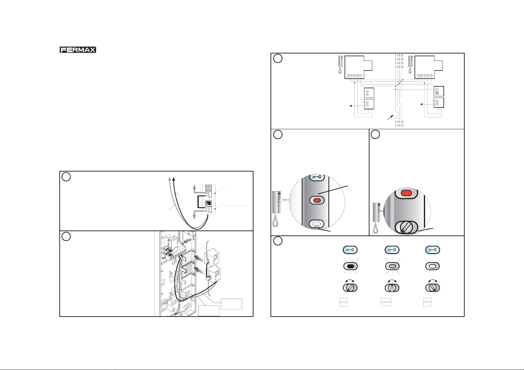
Comprobar que tiene el recorri-
do, tal y como muestra la figura:
* izquierda-centro-derecha.
Si no gire al tope izquierdo y vuel-
va a repetir el proceso desde el 5
paso.
Test the path as it is shown in the
figure:
* left-middle-right.
If not turn it to the left bottom and
you should repeat again the
operation from the step nº 5 again.
KIT REGULADOR DE LLAMADA CITYMAX Ref. 2498
CITYMAX VOLUME CONTROL KIT Ref. 2498
Este kit se ha diseñado para tener la posibilidad de regular el volumen de la llamada desde
su valor máximo hasta un nivel apenas audible. El indicador luminoso (LED), se enciende de
forma proporcional a como se reduce el nivel de volumen, de forma que queda totalmente
iluminado cuando el volumen está al mínimo.
This kit has been designed to allow the call sound to be regulated. A light indicator (LED)
warns that the device is reduced. It includes a volume control which regulates the call sound
from a maximum up to a minimum value. A LED indicator lights on in proportion to the
volume control, in a way that the light is full on when the call volume control is at
minimum.
Este kit sólo se puede instalar en Teléfonos CityMax EXTRA y/o COMPLET.
This kit is for CityMax EXTRA and/or COMPLET telephones only.
Pasos para el montaje del kit:
Sequence to install the kit:
Cablear los módulos, tal y como
muestra el dibujo entre los termi-
nales L, K, A y 4.
Plug-in the wires in the
corresponding terminals following
the attached installation diagram,
(terminals L, K, A and 4).
Encajar en las casillas y conec-
tar a los terminales 3 y 4 del telé-
fono, tal y como se muestra en la
figura.
Place it the modules into the
telephone and connect it to
terminals 3 & 4 of the connector
as shown in the figure.
Cod.94511 V02/03
2
1
LED
REGULADOR
DE LLAMADA
VOLUME CONTROL
LED
616E
+ 12 Vdc
+ 12 Vdc
HILO DE LLAMADA
CALL WIRE
34
TO 4 TERMINAL
RED Wire
AL TERMINAL 4
C ble ROJO
TO 3 TERMINAL
BLACK Wire
AL TERMINAL 3
C ble NEGRO
AL TELEFONO (TERMINALES 3 y 4)
LED
REGULADOR DE LLAMADA
TO 4 TERMINAL
RED Wire
AL TERMINAL 4
C ble ROJO
TO 3 TERMINAL
BLACK Wire
AL TERMINAL 3
C ble NEGRO
TO TERMINALS 3 & 4 OF THE TELEPHONE
LED
VOLUME CONTROL
CALL WIRE
+ 12 Vdc
4
L
A
K
HILO DE LLAMADA
+ 12 Vdc
min. volumen
min. volume
medio volumen
middle volume
m x. volumen
max. volume
Cablear los teléfonos en
la Instalación General. Se
adjunta el esquema de insta-
lación.
El terminal «A» se debe co-
nectar a + 12 Vdc.
Wiring the telephones to Ge-
neral Installation. Attached is
the Wiring Diagram.
«A» terminal must be
connected to + 12 Vdc.
Colocar la tapa y atornillar. Colocar el pro-
tector de luz y la base para el botón de volu-
men
Place the cover and screws it. Now, light pro-
tector and volume knob can be fitted on
telephone.
Colocar el botón regulador en la posición que
se muestra en la figura. Tras colocarlo, gírelo
varias veces de un extremo a otro, para afian-
zarlo en la posición correcta, y comprobar su
funcionamiento.
After placing the knob, twist it several times
from one bottom to the other one, in order to fit
it in the correct position and check its operation.
3
4
Protector luz
Light protector
Botón regulador
Volume knob
5
Basebotónvolumen
Volume knob base
6
Máxima
iluminación
Maximum
lighting
Media
iluminación
Middle
lighting
Mínima
iluminación
Minimum
lighting
Negro / lack
Rojo / Red
4DE LLAMADA
L
K
ALED
REGULADOR
1
+
+ 12 Vdc
234612346
Negro / lack
Rojo / Red
1
2
3
6
VOLUME CONTROL
LED
4DE LLAMADA
L
K
ALED
REGULADOR
VOLUME CONTROL
LED
Hilo de
ll m d
Call wire
DE LA INSTALACION GENERAL
TO GENERAL INSTALLATION
Hilo de
ll m d
Call wire


