Gemu eSyDrive R649 User manual

GEMÜ R649 eSyDrive
Motorized diaphragm valve
Operating instructions
EN
further information
webcode: GW-R649

All rights including copyrights or industrial property rights are expressly reserved.
Keep the document for future reference.
© GEMÜ Gebr. Müller Apparatebau GmbH & Co. KG
07.04.2021
www.gemu-group.com2 / 50GEMÜ R649 eSyDrive

Contents
1 General information .................................................. 4
1.1 Information .......................................................... 4
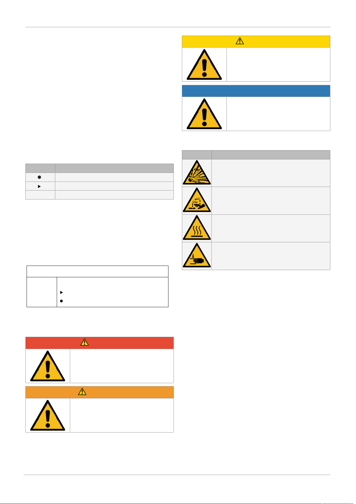
1.2 Symbols used ...................................................... 4
1.3 Definition of terms .............................................. 4
1.4 Warning notes ..................................................... 4
2 Safety information .................................................... 5
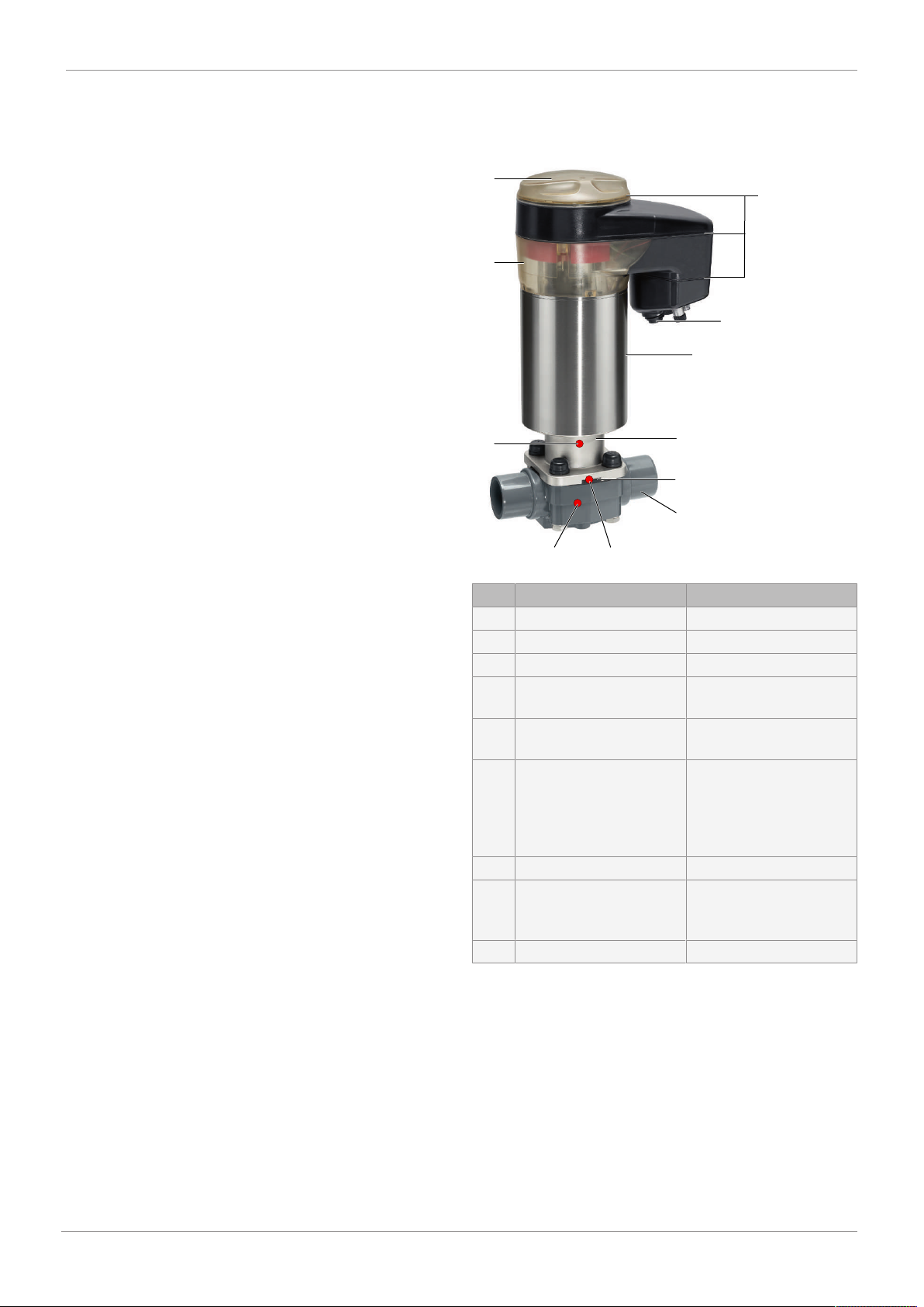
3 Product description ................................................... 5
3.6 Product label ....................................................... 7
4 Correct use ............................................................... 7
5 Order data ................................................................. 9
5.1.11 ................................................................. 9
6 Technical data .......................................................... 11
6.3 .............................................................................. 11
6.6 .............................................................................. 12
6.7.6 ................................................................. 15
7 Dimensions ............................................................... 16
7.4 Availability of mounting plate ............................. 30
8 ................................................................................. 31
9 Manufacturer's information ....................................... 33
9.1 Delivery ................................................................ 33
9.2 Packaging ............................................................ 33
9.3 Transport ............................................................. 33
9.4 Storage ................................................................. 33
10 Installation in piping .................................................. 33
10.1 Preparing for installation .................................... 33
10.2 Installation position ............................................ 34
10.3 Installation with clamp connections .................. 34
10.4 Installation with butt weld spigots ..................... 35
10.5 Installation with threaded sockets ..................... 35
10.6 Installation with threaded spigots ...................... 35
10.7 Installation with flanged connection .................. 35
11 Electrical connection ................................................. 37
11.6 .............................................................................. 39
12 Network connection .................................................. 40
12.1 Network settings ................................................. 40
12.2 Connecting the network ...................................... 40
12.3 Resetting the network settings ........................... 40
13 Commissioning ......................................................... 40
14 Operation .................................................................. 40
14.1 Operation on the device ...................................... 40
14.2 Operation via the web server .............................. 40
14.3 Manual override ................................................... 40
15 Inspection and maintenance ...................................... 41
16 Troubleshooting ........................................................ 45
17 Removal from piping ................................................. 46
18 Disposal .................................................................... 46
19 Returns ..................................................................... 46
20 Declaration of Incorporation according to 2006/42/
EC (Machinery Directive) ........................................... 47
21 Declaration of conformity according to 2014/68/EU
(Pressure Equipment Directive) ................................. 48
22 Declaration of conformity according to 2014/30/EU
(EMC Directive) ......................................................... 49
GEMÜ R649 eSyDrivewww.gemu-group.com 3 / 50

www.gemu-group.com4 / 50GEMÜ R649 eSyDrive
1 General information
1.1 Information
•The descriptions and instructions apply to the standard ver-
sions. For special versions not described in this document
the basic information contained herein applies in combina-
tion with any additional special documentation.
•Correct installation, operation, maintenance and repair work
ensure faultless operation of the product.
•Should there be any doubts or misunderstandings, the Ger-
man version is the authoritative document.
•Contact us at the address on the last page for staff training
information.
1.2 Symbols used
The following symbols are used in this document:
Symbol Meaning
Tasks to be performed
Response(s) to tasks
– Lists
1.3 Definition of terms
Working medium
The medium that flows through the GEMÜ product.
1.4 Warning notes
Wherever possible, warning notes are organised according to
the following scheme:
SIGNAL WORD
Type and source of the danger
Possible
symbol for the
specific
danger
Possible consequences of non-observance.
Measures for avoiding danger.
Warning notes are always marked with a signal word and
sometimes also with a symbol for the specific danger.
The following signal words and danger levels are used:
DANGER
Imminent danger!
▶Non-observance can cause death or
severe injury.
WARNING
Potentially dangerous situation!
▶Non-observance can cause death or
severe injury.
CAUTION
Potentially dangerous situation!
▶Non-observance can cause moderate
to light injury.
NOTICE
Potentially dangerous situation!
▶Non-observance can cause damage to
property.
The following symbols for the specific dangers can be used
within a warning note:
Symbol Meaning
Danger of explosion
Corrosive chemicals!
Hot plant components!
Rotating cover!

www.gemu-group.com 5 / 50 GEMÜ R649 eSyDrive
2 Safety information
The safety information in this document refers only to an indi-
vidual product. Potentially dangerous conditions can arise in
combination with other plant components, which need to be
considered on the basis of a risk analysis. The operator is re-
sponsible for the production of the risk analysis and for com-
pliance with the resulting precautionary measures and re-
gional safety regulations.
The document contains fundamental safety information that
must be observed during commissioning, operation and main-
tenance. Non-compliance with these instructions may cause:
•Personal hazard due to electrical, mechanical and chemical
effects.
•Hazard to nearby equipment.
•Failure of important functions.
•Hazard to the environment due to the leakage of dangerous
materials.
The safety information does not take into account:
•Unexpected incidents and events, which may occur during
installation, operation and maintenance.
•Local safety regulations which must be adhered to by the
operator and by any additional installation personnel.
Prior to commissioning:
1. Transport and store the product correctly.
2. Do not paint the bolts and plastic parts of the product.
3. Carry out installation and commissioning using trained
personnel.
4. Provide adequate training for installation and operating
personnel.
5. Ensure that the contents of the document have been fully
understood by the responsible personnel.
6. Define the areas of responsibility.
7. Observe the safety data sheets.
8. Observe the safety regulations for the media used.
During operation:
9. Keep this document available at the place of use.
10. Observe the safety information.
11. Operate the product in accordance with this document.
12. Operate the product in accordance with the specifications.
13. Maintain the product correctly.
14. Do not carry out any maintenance work and repairs not de-
scribed in this document without consulting the manufac-
turer first.
In cases of uncertainty:
15. Consult the nearest GEMÜ sales office.
3 Product description
3.1 Construction
8
91
2
3
4
5
6
7
7 7
Item Name Materials
1 O-rings EPDM
2 Electrical connections
3 Actuator top 1.4301
4 Distance piece with leak
detection hole
1.4008
5 Diaphragm EPDM, FKM, NBR, PTFE/
EPDM
6 Valve body PVC-U grey, ABS, PP rein-
forced, PVDF, inliner PP-H,
grey outliner PP rein-
forced, inliner PVDF/out-
liner PP, reinforced
7 Optical position indicator PESU
8 Cover with high visibility
LED, manual override and
on-site control
PESU
9 CONEXO RFID chip
3 Product description

www.gemu-group.com6 / 50GEMÜ R649 eSyDrive
3 Product description
3.2 Buttons for on-site control
8
9
10
Fig.1: Position of the buttons
Item Name Function
8 DIP switch, "ON-
site" control
Switches the on-site
control on the device
on or off
9 "OPEN" button Moves actuator to the
open position
Resets the network
settings
10 "INIT/CLOSE" but-
ton
Moves actuator to the
closed position
Starting initialisation
3.3 LED displays
3.3.1 On-site status LEDs
LED MODE LED PWR
Fig.2: Position of the status LEDs
The user checks the following conditions directly on-site at
the valve using LED MODE and LED PWR:
Function LED MODE LED PWR
Yellow Blue Green Red
Automatic oper-
ation
Manual opera-
tion
Actuator
switched off
(OFF mode)
Manual opera-
tion (on-site)
Software update
alternating
On-site initialisa-
tion (buttons)
Remote initial-
isation (via Di-
gIn)

www.gemu-group.com 7 / 50 GEMÜ R649 eSyDrive
Function LED MODE LED PWR
Yellow Blue Green Red
Operation via
emergency
power supply
module
3.3.2 High visibility LEDs
11
11 11
11 11
11
Fig.3: Position of the high visibility LEDs
Item Name
11 High visibility LEDs
Function High visibility LED
Green Orange
OPEN position Position indicator
LEDs,
standard
OPEN position Position indicator
LEDs,
inversed
CLOSED position Position indicator
LEDs,
standard
CLOSED position Position indicator
LEDs,
inversed
Position unknown (e.g. 50%)
Initialisation
alternating
Function High visibility LED
Green Orange
Location function
3.4 Description
The GEMÜ R649 2/2-way diaphragm valve has a hollow shaft
actuator and is electrically operated. The eSyDrive hollow
shaft actuator can be operated as an ON/OFF actuator or as
an actuator with integrated positioner or process controller.
An integral optical and electrical position indicator is stand-
ard.
3.5 Function
The product controls or regulates (depending on version) a
flowing medium by being closed or opened by a motorized ac-
tuator.
The product has an optical position indicator as standard. The
optical position indicator indicates the OPEN and CLOSED po-
sitions.
3.6 Product label
The product label is located on the actuator. Product label
data (example):
Design in accordance with order data
Device-specific data
Year of manufacture
Item number Traceability number Consecutive number
- XXXXXXXX|YYYY
The month of manufacture is encoded in the traceability num-
ber and can be obtained from GEMÜ. The product was manu-
factured in Germany.
The operating pressure stated on the product label applies to
a media temperature of 20 °C. The product can be used up to
the maximum stated media temperature. You can find the
pressure/temperature correlation in the technical data.
4 Correct use
DANGER
Danger of explosion
▶Risk of death or severe injury.
●Do not use the product in potentially
explosive zones.
4 Correct use

www.gemu-group.com8 / 50GEMÜ R649 eSyDrive
4 Correct use
WARNING
Improper use of the product
▶Risk of severe injury or death.
▶Manufacturer liability and guarantee will be void.
●Only use the product in accordance with the operating
conditions specified in the contract documentation and in
this document.
The product is designed for installation in piping systems and
for controlling a working medium.
The product is not intended for use in potentially explosive
areas.
●Use the product in accordance with the technical data.

5 Order data
The order data provide an overview of standard configurations.
Please check the availability before ordering. Other configurations available on request.
Order codes
1 Type Code
Diaphragm valve, electrically operated,
electro-mechanical hollow shaft actuator,
eSyDrive
R649
2 DN Code
DN 12 12
DN 15 15
DN 20 20
DN 25 25
DN 32 32
DN 40 40
DN 50 50
DN 65 65
3 Body configuration Code
2/2-way body D
4 Connection type Code
5 Valve body material Code
PVC-U, grey 1
ABS 4
PP, reinforced 5
PVDF 20
Inliner PP-H, grey,
outliner PP, reinforced
71
Inliner PVDF/outliner PP, reinforced 75
PP-H, natural N5
6 Diaphragm material Code
NBR 2
FKM 4
PTFE/EPDM one-piece 54
PTFE/EPDM two-piece 5M
7 Voltage/Frequency Code
24 V DC C1
8 Control module Code
ON/OFF, positioner and process controller L0
9 Actuator version Code
10 Mounting plate Code
With mounting plate M
Without
5 Order data
www.gemu-group.com 9 / 50 GEMÜ R649 eSyDrive

Order example
Ordering option Code Description
1 Type R649 Diaphragm valve, electrically operated,
electro-mechanical hollow shaft actuator,
eSyDrive
2 DN 40 DN 40
3 Body configuration D 2/2-way body
4 Connection type 0 Spigot DIN
5 Valve body material 1 PVC-U, grey
6 Diaphragm material
7 Voltage/Frequency C1 24 V DC
8 Control module L0 ON/OFF, positioner and process controller
9 Actuator version 2A Actuator size 2
10 Mounting plate Without
11
5 Order data
www.gemu-group.com10 / 50GEMÜ R649 eSyDrive

6 Technical data
6.1 Medium
Working medium: Corrosive, inert, gaseous and liquid media which have no negative impact on the physical and
chemical properties of the body and diaphragm material.
6.2 Temperature
Ambient temperature: Valve body material Media temperature
PVC-U, grey (code 1) 10 — 60 °C
ABS (code 4) 10 — 60 °C
PP, reinforced (code 5) 5–80 °C
PVDF (code 20) -10 — 80 °C
Inliner PP-H grey / outliner PP, reinforced (code
71)
5–80 °C
Inliner PVDF / outliner PP, reinforced (code 75) -10 — 80 °C
PP-H, natural (code N5) 5–80 °C
6.3
GEMÜ R649 eSyDrivewww.gemu-group.com 11 / 50
6 Technical data

6.4 Product compliance
Pressure Equipment Dir-
ective:
2014/68/EU
Machinery Directive: 2006/42/EC
EMC Directive: 2014/30/EU
Technical standards used:
Interference resistance DIN EN 61000-6-2
Interference emission EN 61800-3
Category C3
The product is intended for operation in industrial
environments.
Food: Regulation (EC) No. 1935/2004*
Regulation (EC) No. 10/2011*
FDA*
* depending on version and/or operating parameters
6.5 Materials
Materials: Diaphragm material O-ring material
PTFE FKM
NBR EPDM
FKM FKM
EPDM EPDM
6.6
6.7 Electrical data
Supply voltage: Actuator size 0 Actuator size 1 Actuator size 2
Voltage Uv = 24 V DC ± 10%
Rating Max. 28 W Max. 65 W Max. 120 W
Operating mode
(OPEN/CLOSE opera-
tion)
Continuous duty
Operating mode (con-
trol operation)
Class C acc. to EN 15714-2
Reverse battery protec-
tion
Yes
6.7.1 Analogue input signals
6.7.1.1 Set value
Input signal: 0/4 - 20 mA; 0 – 10 V DC (selectable using software)
Input type: passive
Input resistance: 250 Ω
Accuracy/linearity: ≤ ±0.3% of full flow
Temperature drift: ≤ ±0.1% / 10°K
Resolution: 12 bit
www.gemu-group.com12 / 50GEMÜ R649 eSyDrive
6 Technical data

Reverse battery protec-
tion:
No
Overload proof: Yes (up to ± 24 V DC)
6.7.1.2 Process actual value
Input signal: 0/4 - 20 mA; 0 – 10 V DC (selectable using software)
Input type: passive
Input resistance: 250 Ω
Accuracy/linearity: ≤ ±0.3% of full flow
Temperature drift: ≤ ±0.1% / 10°K
Resolution: 12 bit
Reverse battery protec-
tion:
No
Overload proof: Yes (up to ± 24 V DC)
6.7.2 Digital input signals
Digital inputs: 3
Function: selectable using software
Voltage: 24 V DC
Logic level "1": >14 V DC
Logic level "0": < 8 V DC
Input current: typ. 2.5 mA (at 24 V DC)
6.7.3 Analogue output signals
6.7.3.1 Actual value
Output signal: 0/4 - 20 mA; 0 – 10 V DC (selectable using software)
Output type: Active (AD5412)
Accuracy: ≤ ±1% of full flow
Temperature drift: ≤ ±0.1% / 10°K
Load resistor: ≤ 750 kΩ
Resolution: 10 bit
Overload proof: Yes (up to ± 24 V DC)
Short-circuit proof: Yes
6.7.4 Digital output signals
6.7.4.1 Switching outputs 1 and 2
Design: 2x change-over contact, potential-free
GEMÜ R649 eSyDrivewww.gemu-group.com 13 / 50
6 Technical data

Switch rating: 125 V AC / 2 A
48 V DC / 2 A
Switch points: Adjustable 0 - 100 %
6.7.4.2 Switching output 3
Function: Signal fault
Type of contact: Push-Pull
Switching voltage: Supply voltage
Switching current: ≤ 0.1 A
Drop voltage: Max. 2.5 V DC at 0.1 A
Overload proof: Yes (up to ± 24 V DC)
Short-circuit proof: Yes
Pull-Down resistance: 120 kΩ
6.7.5 Communication
Interface: Ethernet
Function: Parameterisation via web browser
IP address: 192.168.2.1 alterable via web browser
Subnet screen: 255.255.252.0 alterable via web browser
The actuator and the PC must be in the same network to use the web server. The IP address of the actuator is entered in the
web browser and the actuator can then be parametrised. In order to use more than one actuator, a definitive IP address must be
assigned to each actuator in the same network.
www.gemu-group.com14 / 50GEMÜ R649 eSyDrive
6 Technical data

6.7.6
GEMÜ R649 eSyDrivewww.gemu-group.com 15 / 50
6 Technical data

7 Dimensions
7.1 Actuator dimensions
B2
ØB
B1
B3
A1
CT*
A
MG
DN Actuator
version
A A1 B B1 B2 B3
10 10 - 20 0A 230.0 44.0 68.0 126.0 160.0 190.0
20 15 - 25 0A 237.0 44.0 68.0 126.0 160.0 190.0
15 - 25 1A 299.0 83.0 82.0 132.0 172.0 250.0
25 32 1A 305.0 83.0 82.0 132.0 172.0 250.0
40 40, 50 1A 303.0 75.0 82.0 132.0 172.0 243.0
40, 50 2A 360.0 124.0 134.0 157.0 224.0 296.0
50 65 2A 360.0 124.0 134.0 157.0 224.0 296.0
Dimensions in mm, MG = diaphragm size
* CT = A + H1 (see body dimensions)
www.gemu-group.com16 / 50GEMÜ R649 eSyDrive
7 Dimensions

7.2 Body dimensions
7.2.1 Spigot DIN / inch (code 0, 30)
L
c
Ød
H1
H
MG DN Connection types code 1)
0 30
Material code 2)
1 5, 20 71, 75 1 5, 20 71, 75 1, 4
NPS L H H H H1 ød c c c L H H1 ød c
20 15 1/2" 124.0 36.0 - 36.0 10.0 20.0 16.0 - 18.0 141.0 36.0 10.0 21.4 24.0
20 3/4" 144.0 38.0 - 38.0 12.0 25.0 19.0 - 19.0 144.0 38.0 12.0 26.7 27.0
25 1" 154.0 39.0 - 39.0 13.0 32.0 22.0 - 22.0 154.0 39.0 13.0 33.6 30.0
25 32 1¼" 174.0 41.0 - 41.0 15.0 40.0 32.0 - 32.0 174.0 41.0 15.0 42.2 33.0
40 40 1½" 194.0 63.2 - 63.2 23.2 50.0 35.0 - 26.0 194.0 63.2 23.2 48.3 35.0
50 2" 224.0 63.2 - 63.2 23.2 63.0 38.0 - 33.0 224.0 63.2 23.2 60.3 40.0
50 65 2½" 284.0 78.8 78.8 - 38.8 75.0 46.0 46.0 - 284.0 78.8 38.8 73.0 46.0
1) Connection type
Code 0: Spigot DIN
Code 30: Imperial butt weld spigot
2) Valve body material
Code 1: PVC-U, grey
Code 4: ABS
Code 5: PP, reinforced
Code 20: PVDF
Code 71: Inliner PP-H, grey, outliner PP, reinforced
Code 75: Inliner PVDF/outliner PP, reinforced
GEMÜ R649 eSyDrivewww.gemu-group.com 17 / 50
7 Dimensions

7.2.2 Spigot IR (code 20)
L
c
Ød
H1
H
s
MG DN Connection types code 20 1)
Material code 2)
20 71 75
NPS L H H1 ød c s s s
20 15 1/2" 154.0 36.0 10.0 20.0 33.0 - 1.9 1.9
20 3/4" 154.0 38.0 12.0 25.0 33.0 - 2.3 1.9
25 1" 154.0 39.0 13.0 32.0 33.0 - 2.9 2.4
25 32 1¼" 194.0 41.0 15.0 40.0 33.0 - 3.7 2.4
40 40 1½" 194.0 63.2 23.2 50.0 33.0 - 4.6 3.0
50 2" 224.0 63.2 23.2 63.0 33.0 - 5.8 3.0
50 65 2½" 284.0 78.8 38.8 75.0 43.0 3.6 - -
1) Connection type
Code 20: Spigot for IR butt welding
2) Valve body material
Code 20: PVDF
Code 71: Inliner PP-H, grey, outliner PP, reinforced
Code 75: Inliner PVDF/outliner PP, reinforced
www.gemu-group.com18 / 50GEMÜ R649 eSyDrive
7 Dimensions

7.2.3 Spigot, connection type code 28
c1
L
ød
H1
H
c
3
s
Connection type spigot (code 28) 1), body material PVDF (code 20) 2)
MG DN NPS c c1 ød H H1 L s
10 15 1/2'' 31,0 37,0 20,0 41,0 16,0 134,0 1.9
1) Connection type
Code 28: Spigot for IR butt welding, BCF
2) Valve body material
Code 20: PVDF
Dimensions in mm
MG = diaphragm size
GEMÜ R649 eSyDrivewww.gemu-group.com 19 / 50
7 Dimensions

7.2.4 Union end DIN (code 7 / MG 10)
L1
H1
H
L2
R
ØD
Ød
MG DN Connection type code 7
Material code
1, 20 5, N5 1, 20 5, N5 1, 20 5, N5
R øD ød L1 L2 H H1
10 15 G 1 43.0 20.0 90.0 128.0 125.0 30.0 41.0 15.0 16.0
Connection type union end DIN (Code 7) 1), body material PVC (Code 1), ABS (Code 4), Inline/Outliner (Code 71, 75) 2),
diaphragm size 20 – 40
MG DN NPS ød øD H H1 L1 L2 R
Material
1 4 71 75
20 15 1/2" 20.0 43.0 36.0 10.0 108.0 146.0 150.0 143.0 146.0 G 1
20 3/4" 25.0 53.0 38.0 12.0 108.0 152.0 156.0 146.0 150.0 G 1¼
25 1" 32.0 60.0 39.0 13.0 116.0 166.0 170.0 158.0 162.0 G 1½
25 32 1¼" 40.0 74.0 41.0 15.0 134.0 192.0 196.0 181.0 184.0 G 2
40 40 1½" 50.0 83.0 63.2 23.2 154.0 222.0 222.0 207.0 210.0 G 2¼
50 2" 63.0 103.0 63.2 23.2 184.0 266.0 266.0 245.0 248.0 G 2¾
Connection type union end DIN (Code 7) 1), body material PVC (Code 1), ABS (Code 4), Inline/Outliner (Code 71, 75) 2),
diaphragm size 20 – 40
MG DN NPS ød øD H H1 L1 L2 R
Material
1 4 71 75
20 15 1/2" 20.0 43.0 36.0 10.0 108.0 146.0 150.0 143.0 146.0 G 1
20 3/4" 25.0 53.0 38.0 12.0 108.0 152.0 156.0 146.0 150.0 G 1¼
25 1" 32.0 60.0 39.0 13.0 116.0 166.0 170.0 158.0 162.0 G 1½
25 32 1¼" 40.0 74.0 41.0 15.0 134.0 192.0 196.0 181.0 184.0 G 2
40 40 1½" 50.0 83.0 63.2 23.2 154.0 222.0 222.0 207.0 210.0 G 2¼
www.gemu-group.com20 / 50GEMÜ R649 eSyDrive
7 Dimensions
Table of contents
Other Gemu Control Unit manuals
Popular Control Unit manuals by other brands

Sunway
Sunway SSWC-06-1224-TA user manual

Qcells
Qcells Q.PEAK DUO XL-G11.X / BFG Series Installation and operation manual

GOAL ZERO
GOAL ZERO Yeti Link user manual

protech
protech SORADIO installation instructions

Digi-Code
Digi-Code DC-5035 installation instructions

Delta
Delta MultiChoice T27897 Series owner's manual

COLORKINETICS
COLORKINETICS CM-400 48V EO installation instructions

ES EYE
ES EYE BG96 Developer's guide

Multitech
Multitech MultiConnect mDot MTDOT Series Developer's guide

Hobby King
Hobby King ORANGERX DSMX user manual

Flow Safe
Flow Safe F84L Series Installation & maintenance manual

Keyautomation
Keyautomation 14A Instructions and warnings for installation and use