Elko iNELS RFTM-1 User manual

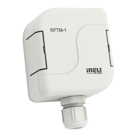
RFTM-1
Wireless pulse converter
EN
02-82/2016 Rev.0
Made in Czech Republic
SENSOR SET
Characteristics /
• The wireless pulse converter detects home energy meters (electric, water, gas) by means of sensors,
and sends them to the wireless unit RFPM-2M.
• The energy gateway RFPM-2M acts as an interface between the meter and a smartphone.
• Measured values are displayed in the application iHC-MAIRF/MIIRF, in daily, weekly or monthly
overview in graphs.
• The sensor is designed for use on existing meters and even without the impulse output“S0”(The
gauge must support scan).
• RFTM-1 transfers consumption from meters using sensors - LS (LED sensor), WS (Magnetic sensor
for meter), MS (Magnetic sensor) or by impulse output („S0“). The sensor does not effect meter
consumption, nor does it interfere with the reading measurements the meter makes.
• For each consumption meter, it is necessary to have one pulse converter RFTM-1.
• The increased IP65 protection is appropriate for mounting in risers, switchboards and other de-
manding environments.
• Battery power (1.5 V / 2x AAA - included in package) with average battery life of around 2 years
(according to the type of scan, frequency of transmissions and pulses).
• Range up to 100 m (in open space), if the signal between the controller and the user is weak, use
the signal repeater RFRP-20 or protocol component RFIO2that support this feature.
• Communication frequency with bidirectional protocol iNELS RF Control.
Radio frequency signal penetration through various construction materials /
1/3
60 - 90 % 80 - 95 % 20 - 60 % 0 - 10 % 80- 90 %
brick walls wooden structures
with plaster boards
reinforced
concrete metal partitions common glass
Indication, settings, types of sensors /
battery holders / • Red LED - pulse indication
- indication of wrong communication
• Green LED - indication of setting mode
- indication of correct communication
• Button SET - long press (> 1s) - activating the Adjustment mode
- short press (< 1s) - Communications Test
• Terminal block for sensor connection
• Set the sensor type:
1 - S0: Meters with pulse output designated as „S0“ (passive contact, open collector, reed
magnetic contacts).
2 - LS: LED sensor (scans LED impulses on the meter, which indicates consumption by
flashing).
3 - MS, WS: Magnetic sensor (scans movement of the numeral, upon which a permanent
magnet is placed).
4...10 - Service
Before starting the programming / manual control, open the actua-
tor housing using a screwdriver. Indication and control units are lo-
cated inside the box.
After completing programming / manual control, snap the housing
closed again.
button /
sensor selection /
terminal blocks /
SENSOR
5 6
4 7
3 8
2 9
1 10
cable gland /
☺
☺
☺
☺
RFRP-20
☺
LED STATUS
LED SET
ELKO EP, s.r.o. | Palackého 493 | 769 01 Holešov, Všetuly | Czech Republic | e-mail: [email protected] | Support: +420 778 427 366
ELKO EP ESPAÑA, S.L. | C/ Josep Martinez 15a, bj | 07007 Palma de Mallorca | e-mail: [email protected] | Tel.: +34 971 751 425 | Fax: +34 971 428 076
www.elkoep.com / www.elkoep.es
Convertidor inalámbrico de impulsos
ES
Característica
• Convertidor inalámbrico de impulsos detecta contadores domésticos (electricidad, agua, gas)
utilizando sensores y lo envía a la unidad inalámbrica RFPM-2.
• Pasarela de energías RFPM-2M es un intermediario entre el contador y teléfono inteligente.
• Los valores medidos se muestran en la aplicación iHC-MARF / MIRF en resumenes gráficos diarios,
semanales o mensuales.
• El sensor está diseñado para su uso en los contadores existentes incluso sin salida de impulsos
„S0“ (los medidores deben proponer la detección de valores).
• RFTM-1 Convierte el consumo de contadores mediante sensores - LS (sensor LED) , MS (sensor
magnético) , WS (sensor magnético para contadores de agua) o salida de impulsos ("S0"). Los
sensores no afectan contador de energía y tampoco afectan a la medición de variables moni-
torizadas.
• Para cada contador de consumo, es necesario tener un convertidor de impulsos RFTM-1.
• La protección IP65 es adecuada para su instalación en distribuciones de tuberías, cuadros eléctri-
cos u otros entornos exigentes.
• Alimentación por baterias (1.5V / 2 x AAA - incluido en embalaje) duración de baterias es de
aproximadamente 2 años (dependiendo de la cantidad de información trasmitida - impulsos).
• Alcance de hasta 100 mts (al aire libre), en caso de señal insuficiente entre controlador y la unidad se
puede utilizar el repetidor RFRP-20 o unidades con protocolo RFIO2, las cuales tienen esta función.
• Frecuencia de comunicación con protocolo bidireccional iNELS RF Control.
Transmisión de señales de radiofrecuencia en varios materiales de la construcción
pared de ladrillo
estructuras de
madera con placas
de yeso
hormigón armado chapas
metálicas vidrio normal
Indicación y programación, tipos de sensores
Antes de la programación / control manual, abre la cubierta de la
unidad con un destornillador. Indicación y botones de control están
dentro de la caja.
Después de la configuración / control manual cierren la cubierta.
soporte de baterías • LED rojo - Indicación de impulsos
- Indicación de comunicación errónea
• LED verde - Indicación del modo de ajuste
- Indicación de la comunicación correcta
• Botón SET - pulsación larga (> 1s) - Activación del modo de confi-
guración
- pulsación corta (< 1s) - Prueba de comunicación
• Terminal para conectar sensores
• Ajuste del tipo de sensor:
1 - S0: Contadores con salida de impulso marcados con "S0" (contacto pasivo, colector
abierto, contacto magnético).
2 - LS: Sensor LED detecta los impulsos del LED en el medidor, que parpadea para indicar
el consumo.
3 - MS, WS: Sensor magnético (detecta los impulsos que están creados con cada rotación
del imán situado en la aguja del dial numérico.
4...10 - Servicio
botón SET
red / rojo
selección del sensor
terminal
pasacables
green / verde

RFTM-1
Wireless pulse converter
EN
02-82/2016 Rev.0
Made in Czech Republic
Sensor connection /
Pull the cable end of the sen-
sor cable through the cable
gland and connect it to the
terminal box (see the individ-
ual sensor instructions for the
wiring diagram).
On the potentiometer, select
the type of connected sensor,
loosen the cable grommet.
Adjust the cable guide inside
the box and tighten the cable
gland.
3
Press SET > 1s to enter RFTM-1
into setting mode, green LED
SET flashes.
Switch on the appliance (gas
stove, faucet, kettle...) de-
pending on the type of ener-
gy being scanned (gas, water,
electricity).
Insert the batteries, observe
the polarity.
4
1 2
5 6
Sensor SET
5 6
4 7
3 8
2 9
1 10
Sensor SET
5 6
4 7
3 8
2 9
1 10
Sensor SET
5 6
4 7
3 8
2 9
1 10
Sensor SET
5 6
4 7
3 8
2 9
1 10
+
-
+
-
Press the SET < 1s button to
exit the setting mode. (After
5 minutes, the adjustment
mode ends automatically.)
Attach the sensor to the scan-
ning position. The cable must
be loose. Check the scanning
accuracy - the red LED blinks
when the pulse is detected.
Clean the sensor surface (de-
pending on the sensor type)
and attach the sensor. The red
LED blinks when the pulse is
detected. *
7 8 9
Sensor SET
5 6
4 7
3 8
2 9
1 10
+
-
+
-
Sensor SET
5 6
4 7
3 8
2 9
1 10
+
-
+
-
Pairing with RFPM-2M /
xxxxxx
address /
For pairing with RFPM-2M, the address on the side of the component is the par-
ing address. RFTM-1 can be paired with one RFPM-2M.
Press SET < 1s to test communication with paired RFPM-2M.
Success rate indication:
- Green LED blinks - the connection is successful.
- Red LED blinks - no or bad connection - relocate the RFTM-1.
Position the RFTM-1 within the range of the gauging gauge and fasten with
suitable bonding material according to the type of substrate (gluing, round
head screws - maximum head diameter 8 mm, maximum thread diameter 4 mm,
minimum length 30 mm).
Because of the significantly reduced throughput of the RF signal with metal
partitions, it is not recommended to install it inside metal switchboards.
Assembly /
2/3
Sensor SET
5 6
4 7
3 8
2 9
1 10
* If the sensor type is incorrectly adjusted, adjust the sensor type on the rotary switch and press
the SET < 1s key.
ELKO EP, s.r.o. | Palackého 493 | 769 01 Holešov, Všetuly | Czech Republic | e-mail: [email protected] | Support: +420 778 427 366
ELKO EP ESPAÑA, S.L. | C/ Josep Martinez 15a, bj | 07007 Palma de Mallorca | e-mail: [email protected] | Tel.: +34 971 751 425 | Fax: +34 971 428 076
www.elkoep.com / www.elkoep.es
Convertidor inalámbrico de impulsos
ES
Conexión del sensor
En el potenciómetro, selec-
cione el tipo de sensor para
conectar, afloje la tuerca pa-
sacables. Pase el extremo del cable del
sensor a través del tuerca pa-
sacables y conéctelo al termi-
nal (la esquema de conexión
consulte en las instrucciones
individuales de sensores).
Ajuste el cable dentro de la
caja y apriete la tuerca pasa-
cables.
Inserte las pilas, tenga cuidado
con la polaridad.
Dependiendo del tipo de en-
ergía controlada (gas, agua,
electricidad), encienda el
aparato (estufa de gas, grifo,
hervidor de agua ...).
Limpiar la superficie de la par-
te captante (según el tipo del
sensor) y adjunte el sensor al
contador. Al detectar el pulso
el LED rojo parpadeará . *
Sujeta el sensor al la posición
de la detección. El cable debe
estar suelto. Al detectar el pul-
so el LED rojo parpadeará.
Al pulsar botón SET < 1s el
modo de configuración se
acaba. (Después de 5 minutos,
el modo de configuración se
termina automáticamente.)
Al pulsar botón SET > 1s el
RFTM-1 se pone en modo
de configuración, el LED SET
verde parpadeará.
Emparejar con RFPM-2M
dirección
Para emparejar con el RFPM-2M se utiliza la dirección, indicada en el lateral
del dispositivo. RFTM-1 se puede emparejar con un RFPM-2M.
Al pulsar botón SET < 1s se prueba la comunicación con RFPM-2M. Indicación de
una conexión exitosa:
- parpadeará el LED verde - conexión exitosa.
- parpadeará el LED rojo - ninguna o mala conexión - es necesario reubicar RFTM-1.
El dispositivo RFTM-1 se debe ubicar dentro del rango del contador y sujetarlo
con material de unión adecuado según el tipo de base de montaje (pegado,
tornillos de cabeza redonda - diámetro máximo de la cabeza 8 mm, diámetro
máximo de rosca 4 mm, longitud mínima 30 mm).
Debido a la reducción significativa del rendimiento de la señal RF con separacio-
nes de metal, no se recomienda instalarlo dentro de cuadros metálicos.
Montaje
* Al ajustar el tipo de sensor incorrectamente, ajuste el tipo de sensor con el interruptor giratorio
y presione el botón SET < 1s .

RFTM-1
Wireless pulse converter
EN
02-82/2016 Rev.0
Made in Czech Republic
Sensor SET
5 6
4 7
3 8
2 9
1 10
+
-
+
-
Sensor SET
5 6
4 7
3 8
2 9
1 10
3/3
1
Replacement of a battery /
2
Open the actuator housing
using a screwdriver.
Remove the original batteries
and insert new batteries into
the battery holder (do not use
new and used batteries to-
gether). Observe the polarity.
Snap on the cover.
3
+
-
+
-
Safe handling /
When handling a device unboxed it is important to avoid contact with liquids. Avoid contact
with the components of the device.
Technical parameters /
Sensor SET
5 6
4 7
3 8
2 9
1 10
+
-
+
-
Instruction manual is designated for mounting and also for user of the device. It is always a part of its packing.
Installation and connection can be carried out only by a person with adequate professional qualification upon un-
derstanding this instruction manual and functions of the device, and while observing all valid regulations. Trouble-
free function of the device also depends on transportation, storing and handling. In case you notice any sign of
damage, deformation, malfunction or missing part, do not install this device and return it to its seller. It is necessary
to treat this product and its parts as electronic waste after its lifetime is terminated. Before starting installation, make
sure that all wires, connected parts or terminals are de-energized. While mounting and servicing observe safety
regulations, norms, directives and professional, and export regulations for working with electrical devices. Do not
touch parts of the device that are energized - life threat. Due to transmissivity of RF signal, observe correct location
of RF components in a building where the installation is taking place. RF Control is designated only for mounting in
interiors. The must not be installed into metal switchboards and into plastic switchboards with metal door - trans-
missivity of RF signal is then impossible. RF Control is not recommended for pulleys etc. - radiofrequency signal can
be shielded by an obstruction, interfered, battery of the transceiver can get flat etc. and thus disable remote control.
Warning
* Pay attention to the operating tempera-
ture of batteries.
Attention:
When you instal iNELS RF Control system,
you have to keep minimal distance 1 cm
between each units.
Between the individual commands must
be an interval of at least 1s.
Power supply
Battery Life:
Indication
Setting mode:
Communications Test -RF STATUS:
Normal operation:
Control
Manual control:
Sensor Selection:
Supported sensors:
(not included in the package)
Output
Sending RF communication packet:
Rangein free space:
Other data
Working temperature:
Storagetemperature:
Operating position:
Protection:
Cross-section of connecting wires:
Dimension:
Weight:
ELKO EP, s.r.o. | Palackého 493 | 769 01 Holešov, Všetuly | Czech Republic | e-mail: [email protected] | Support: +420 778 427 366
ELKO EP ESPAÑA, S.L. | C/ Josep Martinez 15a, bj | 07007 Palma de Mallorca | e-mail: [email protected] | Tel.: +34 971 751 425 | Fax: +34 971 428 076
www.elkoep.com / www.elkoep.es
Convertidor inalámbrico de impulsos
ES
Cambio de baterías
Mediante un destornillador
abre la tapa de la unidad.
Retire las batería antiguas y al
soporte de las batería s inserte
las nuevas (nunca mezcle pilas
viejas y nuevas). Tenga cuida-
do con la polaridad.
Cierre la tapa.
Manipulación segura con el dispositivo
Al manipular con el dispositivo sin embalaje es importante evitar el contacto con líquidos.
Evite tocar los componentes en el dispositivo.
Especificaciones técnicas
2x 1.5Vbaterry / pilas AAA
Appr. 2years, (depending on the type of sensor, frequency of transmissions and pulses) /
Aprox.2años (dependiendo del tipo de sensor, frecuencia de transmisiónde impulsos)
green LED ashes -active / LEDverde parpadea -activado
red LED-blinks when the impulse is registered by the sensor
LEDrojo-parpadeará al registrar el impulso del sensor
green LED-communication OK/ LEDverde -comunicaciónOK
red LED-communication ERR / LEDrojo-comunicaciónerrónea
no indication / sin indicación
button SET / botónSET
rotary switch / con potenciómetro
LS (LEDsensor / sensor LED)
MS,WS (magnetic sensor / sensor magnético)
S0(contact, open collector, reed magnetic contacts /
Contacto, colector abierto, contacto magnético)
866 MHz, 868 MHz, 916 MHz
up to / hasta 100 m
-20.. +50 °C*
-30.. +70°C
any / cualquiera
IP65
max./ máx.0.5 -1mm2
72x 62 x 34 mm
104 g
Alimentación
Vida de pilas:
Indicación
Modo de ajuste:
Prueba de comunicación-RF
STATUS:
Funcionamiento normal:
Control
Control manual:
Seleccióndel sensor:
Sensores soportados:
(no forman parte de embalaje)
Salida
Orden RF desde controlador:
Rangoal aire libre:
Más información
Temperatura de funcionamiento:
Temperatura de almacenamiento:
Posiciónde funcionamiento:
Protección:
Seccióncables de conexión:
Dimensiones:
Peso:
* Estar atento a la temperatura de trabajo de
las pilas.
Advertencia:
En la instalación de iNELS RF Control debe
haber una distancia mínima entre las dife-
rentes unidades de un centímetro.
Entre los diferentes ordenes debe pasar al
menos 1s.
El manual de uso está dirigido para la instalación y el usuario del dispositivo. Manual siempre está incluido en
embalaje. La instalación y conexión puede realizar sólo personal con adecuadas cualificaciones profesionales, de
conformidad con todas las regulaciones aplicadas, y que está perfectamente familiarizado con estas instrucciones
y funciones del dispositivo. Función del dispositivo también depende del transporte, almacenamiento y la manipu-
lación. Si se observa cualquier signo de daño, deformación, mal funcionamiento o pieza que falta, no instale este
producto y devolvelo al vendedor. Con el producto y sus componentes debe ser tratado después de su vida útil
como con residuos electrónicos. Antes de iniciar la instalación, asegúrese de que todos los cables, partes o termi-
nales conectados están sin la conexión a la red. En el montaje y el mantenimiento se deben observar las normas de
seguridad, normas, directivas y reglamentos para trabajar con equipos eléctricos. No toque las partes del dispositivo
que están conectadas en la red - puede producir peligro de vida. Debido a la transmisibilidad de la señal RF, observe
la correcta ubicación de los componentes RF en un edificio donde la instalación se lleva a cabo. RF Control está
diseñado para montaje en interiores, las unidades no están diseñados para la instalación en exteriores y espacios
húmedos, no se pueden instalar en cuadros eléctricos de metal y en cuadros eléctricos plásticos con puerta de
metal - lo que empeora transmisividad de la señal RF. RF Control no se recomienda para el control de dispositivos
que ofrecen funciones vitales o para controlar dispositivos tales como bombas, el. calentadores sin termostato,
ascensores, montacargas, etc. - Señal de radiofrecuencia puede estar bloqueado por una obstrucción, interferida,
la batería del controlador puede estar ya sin energía, etc. y por lo tanto el control remoto puede ser incapacitado.
Advertencia
This manual suits for next models
1
Other Elko Media Converter manuals
Elko
Elko inels RFSG-1M User manual
Elko
Elko RFIM-20B User manual

Elko
Elko 7180 User manual

Elko
Elko Inels RFSG-1M User manual
Elko
Elko inelsAir AirTM-100NB User manual

Elko
Elko iNELS RFSG-1M User manual

Elko
Elko inels RFSG-1M User manual

Elko
Elko RFIM-20B User manual
Elko
Elko RFSG-1M User manual

Elko
Elko iNELS RFSG-1M User manual
Popular Media Converter manuals by other brands
Avitech
Avitech Pacific C-SHS user manual
Conrad
Conrad SATA-IDE operating instructions
Baumer
Baumer HUBNER BERLIN HOG 11 Mounting and operating instructions
Seneca
Seneca ZC-SG user manual
Patton electronics
Patton electronics 2021P Installation and operation manual
Hohner Automaticos
Hohner Automaticos PR90 Series user manual
