emaux FSP350-4W User manual

FSP350-4W / FSP400-4W / FSP450-4W / FSP500-4W / FSP650-4W
1.5" VALVE REPLACEMENT PARTS
Used after backwash to flush dirt from valve
Cleaning Filter by reversing the flow
CLOSED Shuts off all flow to filter or pool
RINSE
BACKWASH
FILTER
Valve Position
Normal Filtration and Vacuuming
Function
THIS FILTER OPERATES UNDER HIGH PRESSURE. WHEN ANY PART OF THE CIRCULATING
SYSTEM (e.g., CLAMP, PUMP, FILTER, VALVES, ETC.) IS SERVICED, AIR CAN ENTER THE
SYSTEM AND BECOME PRESSURIZED . PRESSURIZED AIR CAN CAUSE THE LID OR VALVE TO
BE BLOWN OFF WHICH CAN RESULT IN SEVERE INJURY, DEATH, OR PROPERTY DAMAGE
TURN PUMP OFF BEFORE CHANGING VALVE POSITION.
WARNING
!
!
TO PREVENT DAMAGE TO THE PUMP AND FOR PROPER OPERATION OF THE SYSTEM,
CLEAN PUMP STRAINER AND SKIMMER BASKETS REGULARLY.
!
DO NOT UNSCREW SCREWS OF FLANGE CLAMP WHILE PUMP IS RUNNING.
!
Key No.
Part No.
Product Description
Qty
1
03018009
Pin for handle
1
2
01013036
Handle for 1.5" 4-way Valve
1
3
03011003
Ø4*12 Self-drilling screw
5
4
01013040
Pressing Ring
1
5
01013041
Fixation for 1.5" 4-way Valve Handle
1
6
01181003
Washer for 1.5" 4-way Valve Handle
1
7
02011017
O-Ring for Rotor
2
8
89280104
Sight Glass with O-Ring
1
9
01111048
Connector for Pressure Gauge/Stopper
1
10
06021013
Plastic pressure gauge With O-Ring(40Psi)
1
11
02311005
Spider Gasket
1
12
01013098
Lid for for 1.5" 4-way Valve Rotor
1
01021003
Rotor for 1.5" 4-way Valve
1
13
01013039
1.5" 4-way Valve Rotor Connector
1
14
02011021
O-Ring for Rotor Connector
1
15
02011018
O-Ring
1
16
01013038
Base for 1.5" 4-way Valve ( Clamp)
1
17
02011027
O-Ring for 1.5" 4-way Valve ( Thread)
1
02011028
O-Ring for 1.5" 4-way Valve ( Clamp)
1
18
89281301
1.5" 4-way Valve Body
1
19
02020013
O-Ring for 1.5" Connector
3
20
01013015
1.5" Connector ( black)
3
21
02011003
O-Ring for 1.5" Union
3
22
01171153
1.5" Union ( A/E)
2
23
01013017
1.5" Union Nut ( black)
3
FILTER & PUMP COMBO
Installation & Operating Instruction
* Install filtration system including pump,filter tank and multiport valve.
* The filter system should be installed as close as possibie to the swimming pool and preferably at a level
of 0.50 metres below the surface of the water in the swimming pool. Make sure there is drainage available
at the place where the filter is to be installed.
* PUMP
1) Only qualified,licensed personnel should install pump and wiring.
2) Electrical Contractors Please Note:All 220 volt 50Hz pump must be wired to the main power supply
trough an approved and correctly rated contractor.
3 Allow for gate valve in suction piping. )
4 Pump suction and discharge connections have moulded in ) thread stops,do not try to screw pipe in
beyond these stops.
* FILTER TANK and MULTIPORT VALVE
1 Loading the sand media.Filter sand media is loaded through the top opening of the filter.)
a Loosen the plastic clamps from tank neck.)
b Cap internal pipe with plastic cap to prevent sand from entering it.)
c We recommend filling tank approximately 1/2 way with water to provide a cushion effect when the filter )
sand is poured in. This helps protect the under-drain laterals from excessive shock.
d Carefully pour in correct amount and grade of filter sand.Be sure center pipe remains centered in ) opening.
Sand surface should be leveled and should come to about the middle of the filter tank.Remove
plastic cap from internal pipe.
2 Assemble filter control valve to filter tank.)
a Insert filter control valve(with O'ring in place)into the tank neck,taking care that the center pipe )
slips into the hole in the bottom of the valve.
b Place two plastic clamps around valve flange and tank neck and tighten just enough so that the )
valve may Be rotated on tank for final positioning.
c Carefully screw pressure gauge(with O'ring in place)into tapped hole in valve body.Do not over-tighten.)
d Connect pump to control valve opening marked PUMP with hose.After connections are made,tighten )
clamps with screwdrive,tapping around clamp with screwdrive handle to help seat valve flange clamp.
3 Make return to pool pipe connection to control valve opening marked RETURN and complete other )
necessary plumbing connections,suction lines to pump,waste,etc.
4 To prevent water leakage,be sure all pipe connections are tight.)
INSTALLATION
41
EMFS16030901

23
REPLACEMENT PARTS OF FILTER
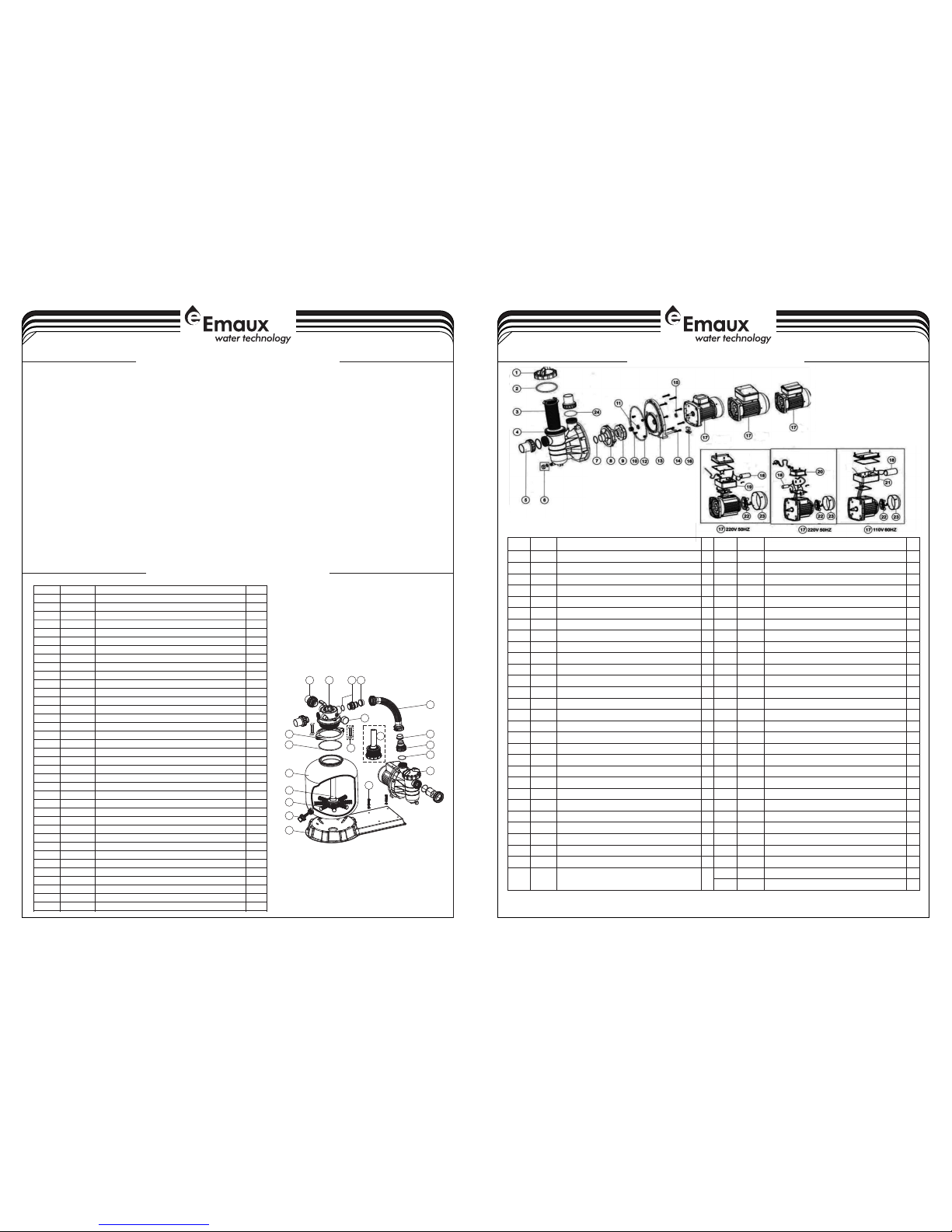
SS PUMP REPLACEMENT PARTS
1) Be sure correct amount of filter media sand is in tank and that all connections have been made and are secure.
2 Depress control valve handle and rotate to BACKWASH position. (To prevent damage to control valve seal, )
3 Prime and start pump. Never tun pump dry! Running pump dry may damage seals,causing leakage and flooding!)
Fill pump with water before starting motor. (be sure all suction and return lines are open), allowing the filter tank
to fill with water. Once water is flowing out of the waste line, run the pump for at least 1 minute. The initial
back-washing of the filter is recommended to remove any impurities or fine sand particles in the sand media.
4 Turn pump off and set valve to RINSE position. Start pump and operate until water in sight glass is clear, about )
normal filter mode, filtering dirt particles from the pool water.
5 Adjust pool suction and return valves to achieve desired flow. Check system and filter for water leaks and tighten)
6 Note the initial pressure gauge reading when the filter is clean. (It will vary from pool to pool depending upon the )
than the initial "clean" pressure you noted, it is time to backwash the filter (see BACKWASH under filter and control
NOTE: During initial clean-up of the pool water it may be necessary to backwash frequently due to the unusually
INSTALL/START-UP OF FILTRATION
always depress handle before turning.)
1/2 to 1 minute. Turn pump off and set valve to FILTER position and restart pump.The filter is now operating in the
connections, bolts, nuts, as required.
pump and general piping system.) As the filter removes dirt and impurities from the pool water, the accumulation
in the filter will cause the pressure to rise and flow to diminish. When the pressure gauge reading is 1.5 bar, higher
heavy initial dirt load in the water.
valve functions).
10
2 1 35
6
5
8
9
16
15
18
17
13
12
11
4
7
14
19
Key No.
Part No.
Description
Qty
1*
88281205
1.5"-4Way Top Mount V alve (B lack/ W hite Colour)
1
2*
89280102
1.5" Union Set W ith O-R ing (Bl ack/ Wh ite Colour)
1
3
89030204
Hose adaptor with O-R ing
1
4
06021001
Plastic Pressure Ga uge wit h O-Rin g (35psi)
1
4
01111048
Connector fo r press ure gau ge/st opper
1
5
02011026
Sleeve for Hos e
2
6
89030301
FSP350-4W Plastic H ose wit h Nut
1
6
89030401
FSP400-4W Plastic h ose wit h Nut
1
6
89030501
FSP450-4W Plastic h ose wit h Nut
1
6
89030601
FSP500-4W Plastic h ose wit h Nut
1
6
89030701
FSP650-4W Plastic h ose wit h Nut
1
7
01013049
Hose adaptor with nut
1
8
02011104
O-Ring for 1.5" Union
1
9
88022401
Pump 0.20hp, 220V/5 0Hz, Si ngle Ph ase
1
9
88022402
Pump 0.33hp, 220V/5 0Hz, Si ngle Ph ase
1
9
88022403
Pump 0.50hp, 220V/5 0Hz, Si ngle Ph ase
1
9
88022404
Pump 0.75hp, 220V/5 0Hz, Si ngle Ph ase
1
9
88022405
Pump 1.00hp, 220V/5 0Hz, Si ngle Ph ase
1
10
89032001
Pump Assembly Screw
2
11
01271010
Clamp Lock
2
12
02011134
O-Ring for Filter Nec k
1
13
01331005
P350 Filter Tank
1
13
01331006
P400 Filter tank
1
13
01331007
SP/P450 Filter tank
1
13
01331008
SP/P500 Filter tank
1
13
01331010
SP/P650 Filter tank
1
14
89011602
P350 Lateral Assemb ly with C enter P ipe
1
15
89011603
P400 Lateral Assemb ly with C enter P ipe
1
15
89011604
P450 Lateral Assemb ly with C enter P ipe
1
15
89011605
P500 Lateral Assemb ly with C enter P ipe
1
15
89011606
P650 Lateral Assemb ly with C enter P ipe
1
16
01172007
Laterals(115mm)
8
16
01172008
Laterals (126mm)
8
17
89011601
Water Drain Set
1
18
01111056
FSP/F350-4-6W Com bo Base
1
18
01111053
FSP/F400-6W - FSP/F 650-6 W Combo b ase
1
19
89010119
M6*50 Screws With Nut
2
Notes:
1* 88281205B is 1.5"-4Way Top Mount Valve in Black Colour
1* 88281205W is 1.5"-4Way Top Mount Valve in White Colour
2* 89280102B is 1.5" Union Set With O-Ring in Black Colour
2* 89280102W is 1.5" Union Set With O-Ring in White Colour
Key No.
Part No .
Descr iption
Qty
Key No.
Part No .
Descr iption
Qty
1
01201 031
Trans parent Lid
1
17
89022 201
Motor S D/SQ/SS/ ST020(22 0V/60HZ)
1
2
02010 247
O-Rin g for Lid
1
17
89022 202
Motor S D/SQ/SS/ ST033(22 0V/60HZ)
1
3
01112 051
Baske t for SS Pump
1
17
89022 203
Motor S D/SQ/SS/ ST050(22 0V/60HZ)
1
4
01021 064
SS Pump P re-Filte r
1
17
89022 204
Motor S D/SQ/SS/ ST075(22 0V/60HZ)
1
5*
89280 105
1.5" Un ion (Black / White Colo ur)
2
17
89022 205
Motor S D/SQ/SS/ ST100(22 0V/60HZ)
1
6
89022 402
Drain P lug With O'R ing
1
17
89022 206
Motor S D/SQ/SS/ ST120(22 0V/60HZ)
1
7
02011 004
O-Rin g for Diffus er
1
17
89022 305
Motor S D/SQ/SS/ ST020(11 0V/60HZ)
1
8
01111 014
Diffu ser
1
17
89022 306
Motor S D/SQ/SS/ ST033(11 0V/60HZ)
1
9
01311 014
Impel ler SS120( 220V/50H Z)
1
17
89022 301
Motor S D/SQ/SS/ ST050(11 0V/60HZ)
1
9
01311 015
Impel ler SD020/ SD50/SQ2 0/SQ50/S S20/SS50/ST20 /ST50
1
17
89022 302
Motor S D/SQ/SS/ ST075(11 0V/60HZ)
1
9
01311 016
Impel ler SD33/S D75/SQ33 /SQ75/SS 33/SS75/ST33/ST75
1
17
89022 303
Motor S D/SQ/SS/ ST100(11 0V/60HZ)
1
9
01311 017
Impeller S D05 0/S D10 0/SQ050/SQ100/SS050/ SS1 00/ ST0 50
1
17
89022 304
Motor S D/SQ/SS/ ST120(11 0V/60HZ)
1
9
01311 018
Impeller S D07 5/S D12 0/SQ075/SQ120/SS075/ SS1 20/ ST0 75
1
18
04016 028
Capac itor for SS/ SD/SQ/ST 050 Pump 110 V
1
9
01311 019
Impel ler SD100/ SQ100/SS 100/ST10 0(220V/50HZ)
1
18
04016 019
Capac itor for SC0 50 & SS/SD/S Q/ST075 Pu mp 110V
1
9
01311 023
Impel ler SD020/ SQ020/SS 020/ST02 0(220V,110V/6 0HZ)
1
18
04016 021
Capacito r for S C07 5 & SS/ SD/ SQ/ST100-124 Pump 110 V
1
9
01311 024
Impel ler SD033/ SQ033/SS 033/ST03 3(220V,110V/6 0HZ)
1
18
04016 009
Capac itor for SS/ SD/SQ/SP /ST050 Pum p
1
10
89022 403
M8 x 16 Scr ew with Wash er
4
18
04016 010
Capac itor for SS/ SD/SQ/SP /ST075 & SC0 50 Pump
1
11
04015 033
1/2" Me chanical S eal
1
18
04016 012
Capac itor for SS/ SD/SQ/SP /ST100-1 20
1
12
02011 090
O-Rin g for Flange
1
18
04016 032
Capac itor for SS/ SD/SQ/ST 020 Pump 110 V
1
13
01021 065
SS Pump F lange
1
18
04016 033
Capac itor for SS/ SD/SQ/ST 033 Pump 110 V
1
14
03011 035
M6 x 30 Scr ew
8
18
04016 030
Capac itor for SS/ SD/SQ/ST 020 AMU020 P/TP(50/ 60Hz)
1
15
02011 156
Motor S linger
1
18
04016 031
Capac itor for SS/ SD/SQ/ST 033 Pump
1
16
89022 404
Motor S upport
1
19
89022 112
Cable B ox for SD,SQ ,SP,ST05 0-120 Pump
1
17
89022 109
Motor S D020/SQ0 20/SS020 /ST020(2 20V/50HZ)
1
20
89022 111
Cable B ox for SQ/ST /SD020-0 33, SS020- SS030 Pump
1
17
89022 110
Motor S D033 (220V /50Hz)
1
21
89021 505
Cable B ox for SA/ ST/ S D 110V
1
17
89022 105
Motor S D050/SQ0 50/SS050 /ST050(2 20V/50HZ)
1
22
01031 027
Cooling Fa n for S S/S D/S Q/S T050-SS/SD/SQ/ST1 20 Pu mp
1
17
89022 106
Motor S D075/SQ0 75/SS075 /ST075(2 20V/50HZ)
1
22
01031 026
Cooling Fa n for S S/S D/S Q/S T020-SS/SD/SQ/ST0 30 Pu mp
1
17
89022 107
Motor S D100/SQ1 00/SS100 /ST100(2 20V/50HZ)
1
23
01031 011
Fan Cov er for SS/SD /SQ/ST02 0-SS/SD/ SQ/ST030 P ump
1
17
89022108
Motor S D120/SQ1 20/SS120 /ST120(2 20V/50HZ)
1
23
01031 010
Fan Cov er for SQ/SP /SS/SD/S T050-SQ/ SP/SS/SD /ST120
1
24
02011 104
O-Rin g for 1.5" Uni on
2
Notes: 5* 8928 0105B i s 1.5" Un ion in Black Colour
5* 89280105W i s 1.5" Un ion in Wh ite Colour
This manual suits for next models
4
Other emaux Lighting Equipment manuals
Popular Lighting Equipment manuals by other brands

American DJ
American DJ WIFLY BAR QA5 User instructions

Lightolier
Lightolier LP Series specification

Home Decorators Collection
Home Decorators Collection MAUVO CANYON L-06005-DEL Use and care guide

Astera
Astera ARC2 user manual

American DJ
American DJ Sparkle LED 3W User instructions

Future Pool
Future Pool SKIMMER 17,5L Installation and maintenance manual