1-4
Models: V900 V1000 V1200(C) / (C) / (C) / V1400
(Link by Nuts type Valves)
EMFI15012281
FUNCTION
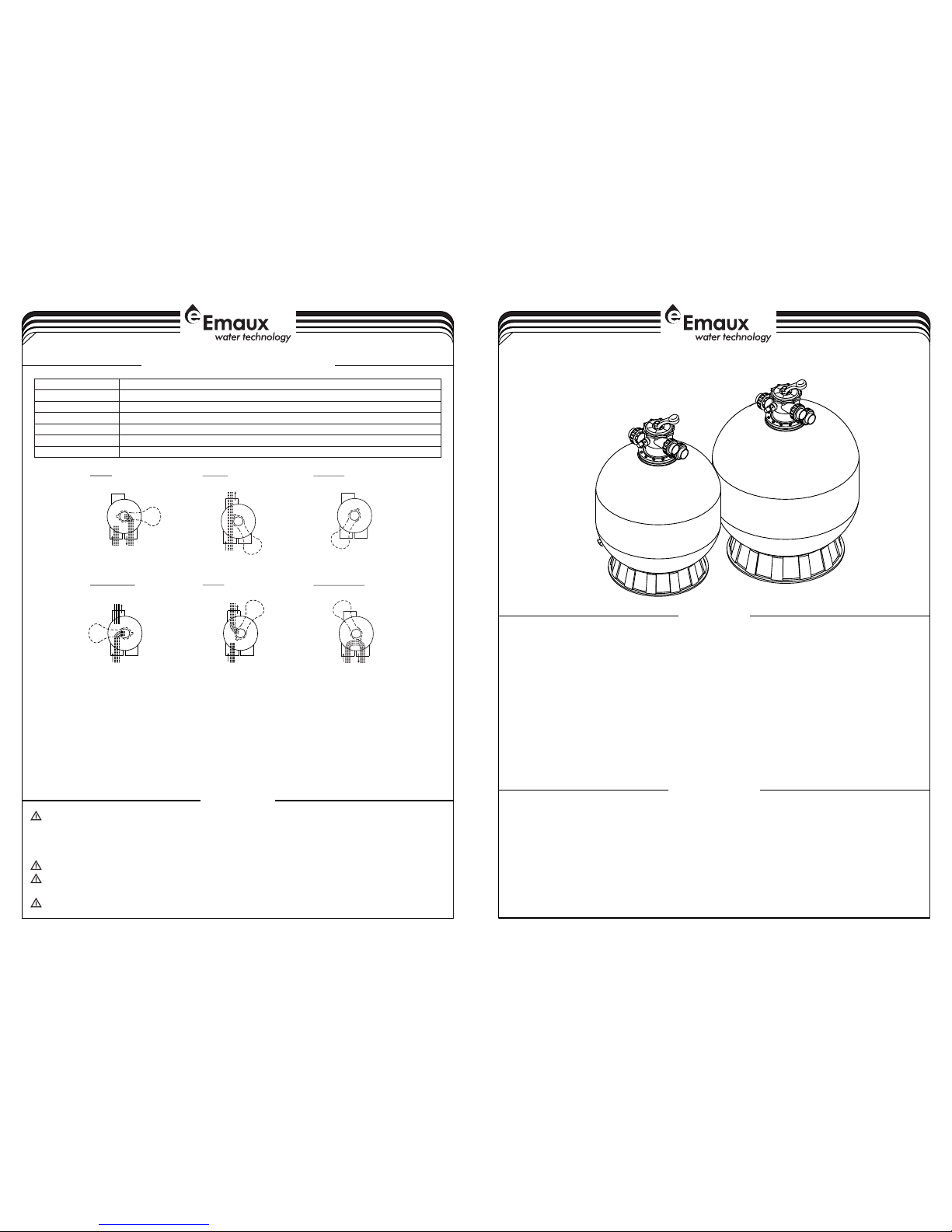
INSTALLATION
The filter uses special filter sand to remove dirt particles from pool water. The filter sand is loaded into the filter tank and
functions as a permanent dirt removing media. When the control valve is in the FILTER position, the pool water which
contains suspended dirt particles, is pumped through your piping system and is automatically directed by the
patented filter control valve to the top of the filter tank. As the pool water is pumped through the filter, dirt particles are
trapped by the sand bed, and filtered out. The cleaned pool water is returned from the bottom of the filter tank,
through the control valve and back to the pool through the piping system. This entire sequence is continuous and
automatic. It provides for total recirculation of pool water through your filter and piping system.
After a period of time, the accumulated dirt in the filter causes a resistance to flow, and the flow diminishes. This means
it is time to clean your filter. With the control valve in the BACKWASH position, the water flow is automatically reversed
through the filter so that it is directed to the bottom of the tank, up through the sand, flushing the previously trapped dirt
and debris out the waste line. Once the filter is back-washed of dirt, set control valve to RINSE position and run pump for
about 1/2 to 1 minute, and then set the control valve in the FILTER position, to resume normal filtering.
NOTE: Turn pump off before changing valve position.
Only simple tools (screwdriver and wrenches), plus pipe sealant for plastic adapters, are required to install and service the
filter.
1) The filter should be placed on a level concrete slab, very firm ground, or equivalent. The filter should be placed
2) Loading the sand media. Filter sand media is loaded through the top opening of the filter.
a) Loosen the flange clamp and remove filter control valve (if previously installed).
b) Cap internal pipe with plastic cap to prevent sand from entering it.
c) We recommend filling the tank approximately 1/2 way with water to provide a cushion effect when the filter sand is
poured in. This helps protect the under-drain laterals from excessive shock.
d) Carefully pour in correct amount and grade of filter sand. (Be sure center pipe remains centered in opening.) Sand
surface should be leveled and should come to about the middle of the filter tank. Remove plastic cap from internal
pipe.
WARNING
4-4
By-passes filter for circulating water to pool
Used after backwash to flush dirt from valve
Cleaning Filter by reversing the flow
By-passes filter, used for vacuuming to waste or lowering water level
CLOSED Shuts off all flow to filter or pool
RECIRCULATE
WASTE
RINSE
BACKWASH
FILTER
Valve Position
Normal Filtration and Vacuuming
Function
FUNCTIONS OF VALVE POSITIONS
WASTE
FILTER
BACKWASH RINSE
WASTE
RECIRCULATE
CLOSED
WASTE WASTE
WASTE WASTE WASTE
IN FLOW OUT FLOW IN FLOW OUT FLOW IN FLOW OUT FLOW
IN FLOW OUT FLOW IN FLOW OUT FLOW IN FLOW OUT FLOW
GENERAL
1) Pipe tap boss provided for optional influent pressure gauge.
2) SERVICING VALVE( Stop pump,close gate valve in suction&discharge before proceeding):
a) Set handle in filter position. b) Remove cover screws. c) Lift cover and key assembly out.
TO ASSEMBLE:
1) Place valve key so that wedge opening is at TOP port (handle in Filter psn.). Flat edge of cover screw lug should
align with flat edge of body screw lug.
2) Position cover O'Ring.
3) Secure assembly to body with cover screws. Tighten cover screws evenly and alternately. Do not over-tighten.
THIS FILTER OPERATES UNDER HIGH PRESSURE. WHEN ANY PART OF THE CIRCULATING SYSTEM
(e.g., CLAMP, PUMP, FILTER, VALVES, ETC.) IS SERVICED, AIR CAN ENTER THE SYSTEM AND
BECOME PRESSURIZED . PRESSURIZED AIR CAN CAUSE THE LID OR VALVE TO BE BLOWN OFF
WHICH CAN RESULT IN SEVERE INJURY, DEATH, OR PROPERTY DAMAGE.
TURN PUMP OFF BEFORE CHANGING VALVE POSITION.
TO PREVENT DAMAGE TO THE PUMP AND FOR PROPER OPERATION OF THE SYSTEM, CLEAN
PUMP STRAINER AND SKIMMER BASKETS REGULARLY.
DO NOT UNSCREW SCREWS OF FLANGE CLAMP WHILE PUMP IS RUNNING.