GB
DESCRIPTION
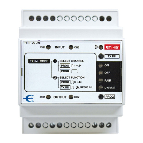
The contact state transmitter together with a suitable receiver is
designed to transmit information specifying a closed or open con-
tact on the input with up to eight switches. The transmitter is placed
in a plastic box designed primarily for built-in installation. The power
supply and input terminals of the transmitter are equipped with
screwless terminals.
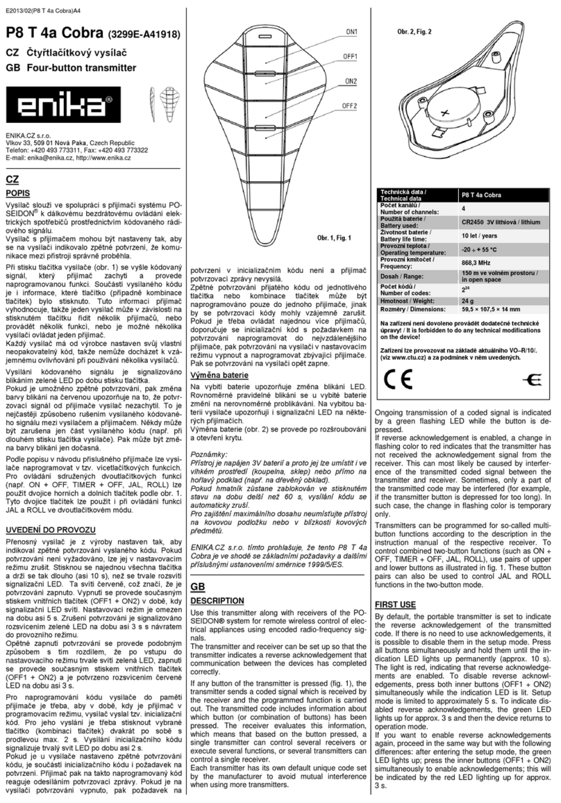
DEVICE FUNCTIONS
If any contact connected to the transmitter is closed or opened, the
transmitter sends a coded signal which is received by the receiver
and the programmed function is carried out.
The transmitter can be used in two basic modes:
Contact state transmitter mode (M1)
When closing the contact connected to one of the eight inputs, the
code corresponding to pressing the ON button is transmitted; when
opening the contact, the code corresponding to pressing the OFF
button is transmitted. In the M1 mode, the transmission of the code
can be limited only to the closed state or, conversely, only to the
open state of the input. The transmission of the code corresponding
to the current state of the input is repeated at regular intervals.
Button mode (M2)
In this mode, the function of the one-button or two-button transmit-
ter is simulated. Pairs of inputs IN1 + IN2 (IN3 + IN4, IN5 + IN6 and
IN7 + IN8) are used for the two-button function. When the contact
on input IN1 (IN3, IN5, IN7) is closed, the code corresponding to
pressing the ON button is transmitted, when the contact on input
IN2 (IN4, IN6, IN8) is closed, the code corresponding to pressing
the OFF button is transmitted. Closing a contact for a period longer
than 0.5 s is evaluated as a long press. The duration of code
transmission in case of permanent closure of a contact is limited to
60 s.
Indication of operating status of the transmitter:
The switching of the contact is signalled by the LED light at the re-
spective input IN1 to IN8. The LED flashes when the coded sig-
nal is transmitted.
FIRST USE
- Fasten the transmitter either by screwing in two corners to a suit-
able base with two screws (max. Ø 5 mm, screw head max. Ø 9
mm), or it can be attached with two tightening straps up to a width
of 6 mm stretched through holes in the rear wall of the receiver, or
the transmitter can be left lying freely in the ceiling.
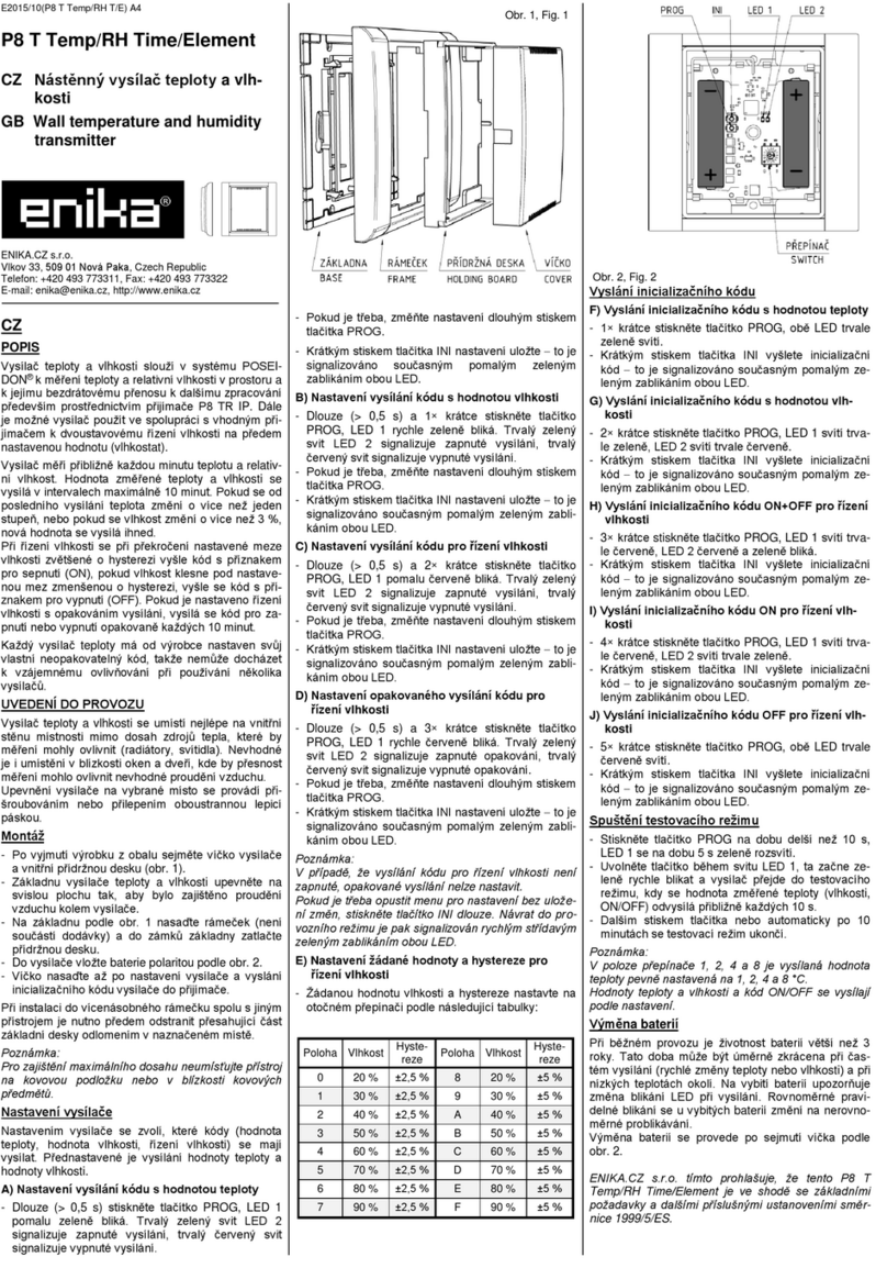
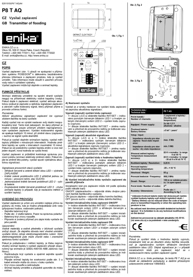
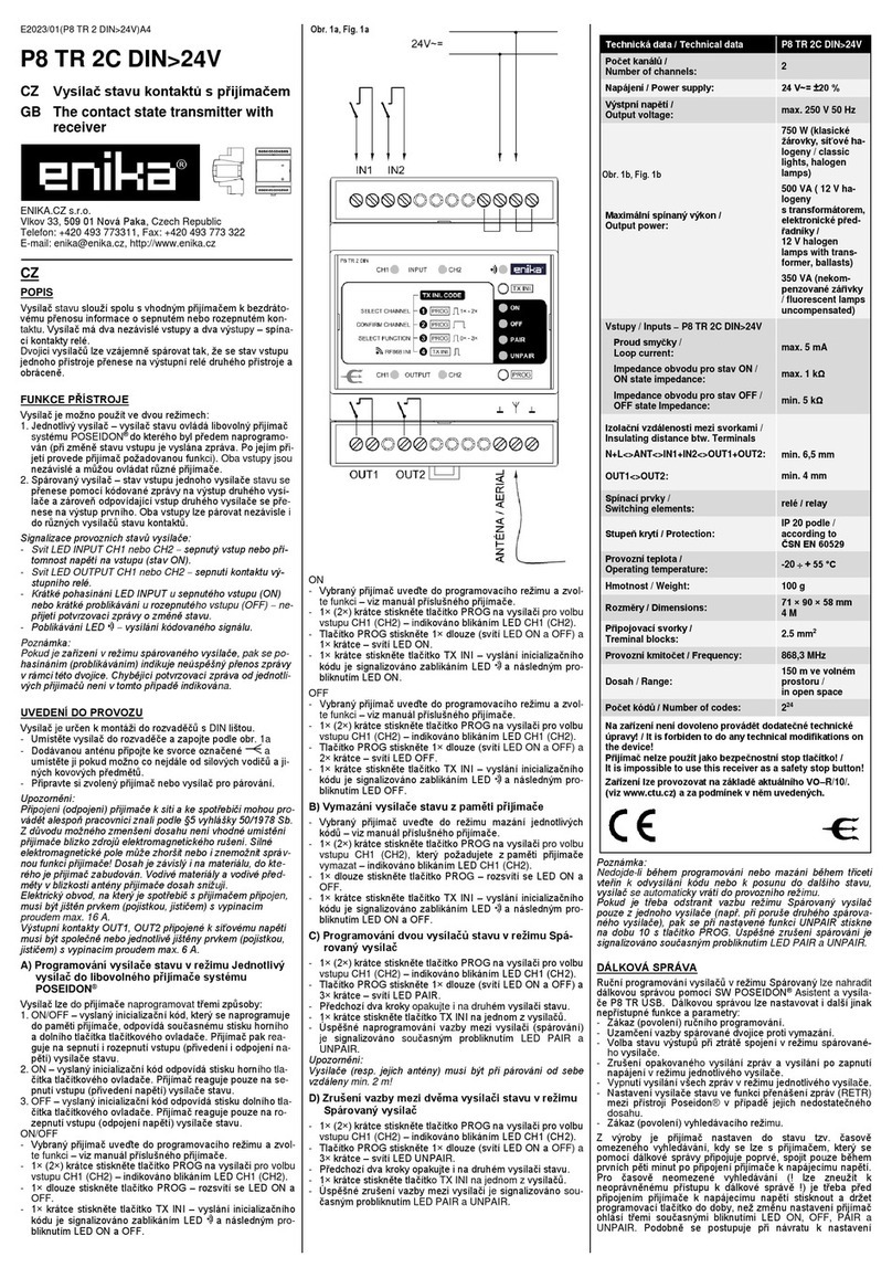
- Connect the transmitter - the power supply and the inputs are
connected according to Fig. 1 using screwless terminals.
- Connect the enclosed antenna to the terminal as far as pos-
sible from power cables and other metal objects.
- Prepare the selected receiver.
Notes:
Only qualified person can connect (disconnect) the receiver to
(from) the mains and appliance. Due to the risk of reducing the de-
tection zone, it is not recommended to locate the receiver near
sources of electromagnetic interference. A strong electromagnetic
field may impair or disable correct functioning of the receiver! The
detection zone depends on the material in which the receiver is
built. Conductive materials and items near the receiver aerial de-
crease its operating range.
The individual inputs are not galvanically separated from each oth-
er and it is not allowed to interconnect them.
When handling antenna circuits, follow the guidelines for handling
electrostatic sensitive circuits.
A) Mode selection
By default, the inputs of the transmitter IN1 to IN8 are set to the
mode of the contact state transmitter (M1) with the repetition of the
transmission in the interval of 10 min.
Input settings can be changed as needed:
Contact state transmitter with ON+OFF status trans-
mission
- Briefly press the INPUT button to select the desired input IN1 to
IN8, while the corresponding LED flashes for the selected input.
- Briefly press the SET button once - the ON, OFF and SET LEDs
light up.
- Confirm by long pressing (> 0.5 s) the SET button - indicated by
double flashing of the BTN and SET LEDs simultaneously.
Contact state transmitter with ON status transmission
- Briefly press the INPUT button to select the desired input IN1 to
IN8, while the corresponding LED flashes for the selected input.
- Briefly press the SET button twice - the ON and SET LEDs light
up.
- Confirm by long pressing the SET button - indicated by double
flashing of the BTN and SET LEDs simultaneously.
Contact state transmitter with OFF status transmis-
sion
- Briefly press the INPUT button to select the desired input IN1 to
IN8, while the corresponding LED flashes for the selected input.
- Briefly press the SET button 3 times - the OFF and SET LEDs
light up.
- Confirm by long pressing the SET button - indicated by double
flashing of the BTN and SET LEDs simultaneously.
One-button transmitter
- Briefly press the INPUT button to select the desired input IN1 to
IN8, while the corresponding LED flashes for the selected input.
- Briefly press the SET button 4 times - the ON, BTN and SET
LEDs light up.
- Confirm by long pressing the SET button - indicated by double
flashing of the BTN and SET LEDs simultaneously.
Two-button transmitter
- Briefly press the INPUT button to select the desired input IN1 to
IN8, while the corresponding LED flashes for the selected input.
- Briefly press the SET button 5 times - the ON, OFF, BTN and SET
LEDs light up.
- Confirm by long pressing the SET button - indicated by double
flashing of the BTN and SET LEDs simultaneously.
Note:
If no mode is confirmed by a long press of the SET button, the next
short press returns to the operating mode. While scrolling through
the mode menu, the LED at the selected input also flashes. In the
menu of the two-button transmitter M2, the LED for the selected in-
put channel and the LED for the corresponding paired input flash-
es. After confirming this menu, the selected mode is set for both in-
puts at the same time. If the setting of the M2 two-button transmit-
ter is changed by the new input setting, the corresponding paired
input will also change to the same input type.
B) Transmitting the initialization code of the contact
state transmitter to the receiver memory
To program the contact status transmitter into the receiver's
memory, the transmitter must send a so-called initialization code
while the receiver is in programming mode. According to the mode
of use, the initialization code can have several forms:
ON/OFF –the receiver processes the transmitted command for
both closing and opening of inputs;
ON –the receiver processes the transmitted command
for closing of inputs only;
OFF –the receiver processes the transmitted command
for opening of inputs only.
Transmitting the initialization code in the contact
state transmitter mode (M1)
1. Select a channel:
- Briefly press the INPUT button to select the desired input IN1 to
IN8, while the corresponding LED flashes for the selected input.
- Confirm the selected channel by long pressing the TX INI but-
ton.
2. Briefly press the TX INI button to select the form of the transmit-
ted code:
- ON + OFF - indicated by LED ON and OFF.
- ON - indicated by the LED ON.
- OFF - indicated by the LED OFF.
3. Set the selected receiver to the programming mode
and select the required function (see the user's manual
of the appropriate receiver).
4. Long press the TX INI button transmit the initialization code in
the selected form into the receiver memory - indicated by flashing
LED .
Notice: If the M1 mode is limited to ON or OFF status transmission
only, only the corresponding ON or OFF initialization code is of-
fered.
Transmitting the initialization code in the button
mode (M2)
1. Select a channel:
- Briefly press the INPUT button to select the desired input IN1 to
IN8, while the corresponding LED flashes for the selected input.
- Confirm the selected channel by long pressing the TX INI but-
ton.
2. Briefly press the TX INI button to select the form of the transmit-
ted code:
- ON + OFF - indicated by ON, OFF and BTN LEDs.
- ON - indicated by ON and BTN LEDs.
- OFF - indicated by OFF and BTN LEDs..
3. Set the selected receiver to the programming mode
and select the required function (see the user's manual
of the appropriate receiver).
4. Long press the TX INI button transmit the initialization code in
the selected form into the receiver memory - indicated by flashing
LED .
Notice: For an input set as one-button M2, only the initialization
code ON is offered. During the selection of the initialization code,
the LED at the corresponding input also flashes, at the paired in-
puts in the M2 two-button mode, both pairs of LEDs flash.
Notes: During the setting of the transmitter and during the trans-
mission of the initialization code, the status of the inputs IN1 to IN8
does not correspond to the status indicated by the respective
LEDs. If there is no shift to the next state within thirty seconds
when selecting inputs, setting inputs, or selecting an initialization
code, the transmitter will automatically return to run mode. Simulta-
neous flashing of LEDs IN1 to IN8 and LEDs ON and OFF indi-
cates an error on one or more input circuits.
CONNECTING THE EXTERNAL ANTENNA
An external antenna must be used in case of range problems or
long distances between transmitter and receiver. Recommended
antenna types: P8 A INT1, P8 A INT2, P8 A EXT1 and P8 A EXT2.
Connect the antenna using a 50Ω coaxial cable. Connect the cen-
ter wire of the cable to the terminal (instead of the wire anten-
na) and connect shielding to the terminal.
Note: Do not place the antenna close to metal parts.
REMOTE MANAGEMENT
Manual programming of transmitters can be substituted by remote man-
agement using the SW POSEIDON® Assistant tool and the P8 TR USB
transmitter. You can use remote management to even set other functions
and parameters that cannot be accessed otherwise (interval of retrans-
mission in M1 mode, long press setting in M2 mode, input negation, input
filter). In addition, the transmitter can be set up remotely in the repeater
function, which allows the radio signal to be transmitted between devices
that are out of range of each other.
By default, the receiver is set to the so-called state of time-limited search.
This means that when a receiver is being connected using remote man-
agement for the first time, it is possible to connect to it only within the first
five minutes from connecting it to the supply voltage. To enable time-
unlimited search (can be misused to gain unauthorized access to remote
management!), it is necessary to press and hold the SET button before
connecting the transmitter to the power supply until the transmitter an-
nounces the setting change by three simultaneous flashes of the ON,
OFF, BTN and SET LEDs. Similarly, use this procedure to return to time-
limited search; the only difference is indication by only one short blink.
Searching for a device can also be completely disabled using remote
management. How the search for the transmitter is set can be found out
while connecting the transmitter to the supply voltage. Three flashes of
the ON, OFF, BTN and SET LEDs signal an unlimited search, one flash
means a time-limited search, no flash means that the search is disabled.
RESET TO DEFAULTS
If you need to cancel all function and parameter settings, you can
return to the manufacturer's default settings.
- Press and hold the SET button on the transmitter while connected
to the power supply until the ON, OFF, BTN and SET LEDs light up
(approx. 10 s).
- While the LEDs are lit up (approx. 3 s), release the SET button
and press it briefly again.
- Restore of factory settings is signaled by simultaneous slow flash-
ing of LED BTN and SET.
Attention!!! When returning to the factory settings, all possibly pro-
grammed codes for retransmission will be deleted from the trans-
mitter's memory!
ENIKA.CZ s.r.o. hereby declares that this P8 T 8C S complies with
the essential requirements and other relevant provisions of Di-
rective 1999/5/EC.


