Poznámka:
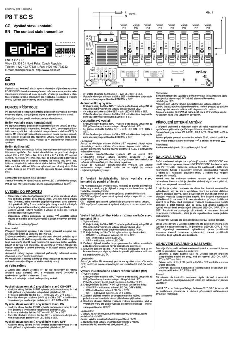
Nedojde-li během programování nebo mazání během třiceti
vteřin k odvysílání kódu nebo k posunu do dalšího stavu,
vysílač se automaticky vrátí do provozního režimu.
Pokud je třeba odstranit vazbu režimu Spárovaný vysílač
pouze z jednoho vysílače (např. při poruše druhého spárova-
ného vysílače), pak se při nastavené funkci UNPAIR stiskne
na dobu 10 s tlačítko PROG. Úspěšné zrušení spárování je
signalizováno současným probliknutím LED PAIR a UNPAIR.
DÁLKOVÁ SPRÁVA
Ruční programování vysílačů v režimu Spárovaný lze nahradit
dálkovou správou pomocí SW POSEIDON®Asistent a vysíla-
če P8 TR USB. Dálkovou správou lze nastavovat i další jinak
nepřístupné funkce a parametry:
- Zákaz (povolení) ručního programování.
- Uzamčení vazby spárované dvojice proti vymazání.
- Volba stavu výstupů při ztrátě spojení v režimu spárované-
ho vysílače.
- Zrušení opakovaného vysílání zpráv a vysílání po zapnutí
napájení v režimu jednotlivého vysílače.
- Vypnutí vysílání všech zpráv v režimu jednotlivého vysílače.
- Nastavení vysílače stavu ve funkci přenášení zpráv (RETR)
mezi přístroji Poseidon® v případě jejich nedostatečného
dosahu.
- Zákaz (povolení) vyhledávacího režimu.
Z výroby je přijímač nastaven do stavu tzv. časově
omezeného vyhledávání, kdy se lze s přijímačem, který se
pomocí dálkové správy připojuje poprvé, spojit pouze během
prvních pěti minut po připojení přijímače k napájecímu napětí.
Pro časově neomezené vyhledávání (! lze zneužít k
neoprávněnému přístupu k dálkové správě !) je třeba před
připojením přijímače k napájecímu napětí stisknout a držet
programovací tlačítko do doby, než změnu nastavení přijímač
ohlásí třemi současnými bliknutími LED ON, OFF, PAIR a
UNPAIR. Podobně se postupuje při návratu k nastavení
časově omezeného vyhledávání, které je ale signalizováno
pouze jedním probliknutím.
Jak je vyhledávání u přijímače nastaveno lze zjistit během
připojení přijímače k napájecímu napětí. Tři probliknutí LED
ON, OFF, PAIR a UNPAIR signalizují neomezené vyhledává-
ní, jedno probliknutí znamená časově omezené vyhledávání,
žádné probliknutí znamená, že je vyhledávání zakázáno.
PŘIPOJENÍ EXTERNÍ ANTÉNY
V případě problémů s dosahem nebo při velké vzdálenosti
mezi přístroji je třeba použit externí anténu.
Doporučené typy antén: P8 A INT1, P8 A INT2, P8 A EXT1
a P8 A EXT2.
Anténu připojte pomocí koaxiálního kabelu 50 Ω. Střední vo-
dič kabelu místo drátové antény ke svorce a stínění ke
svorce .
Anténu neumísťujte do blízkosti kovových částí!
OBNOVENÍ TOVÁRNÍHO NASTAVENÍ
Pokud je třeba zrušit veškeré nastavení funkcí a parametrů
lze se vrátit do původního továrního nastavení:
- Stiskněte a držte tlačítko na přijímači během připojení přijí-
mače k napájecímu napětí do doby, než se rozsvítí LED
ON, OFF, PAIR a UNPAIR (asi 10 s).
- Během svitu těchto LED (asi 3 s) tlačítko uvolněte a znovu
krátce stiskněte.
- Obnovení továrního nastavení je signalizováno současným
probliknutím LED PAIR a UNPAIR.
Upozornění:
Při obnovení továrního nastavení dojde zároveň ke zrušení
vazby režimu Spárovaný vysílač!
Bližší informace najdete na www.enika.cz/poseidon.
ENIKA.CZ s.r.o. tímto prohlašuje, že tento P8 TR 2C/U DIN je
ve shodě se základními požadavky a dalšími příslušnými
ustanoveními směrnice 1999/5/ES.
GB
DESCRIPTION
The contact state transmitter together with a suitable receiver
is designed to transmit information specifying a closed or
open contact (P8 TR 2C DIN) or presence of voltage on the
input (P8 TR 2U DIN). The transmitter contains two independ-
ent inputs and two outputs –relay switching contacts.
It is possible to pair two transmitters so that the state of the
input of one of them is transferred to the output relay of the
other and vice versa.
DEVICE FUNCTIONS
The transmitter can be used in two modes:
1. Single transmitter –the state transmitter controls any re-
ceiver of the POSEIDON®system in which the transmitter
was previously programmed (a message is sent upon the
input state change. The receiver receives the message and
executes the required function.). Both inputs are independ-
ent and can control various receivers.
2. Paired transmitter –the state of the input of one state
transmitter is transferred in a coded message to the output
of the other transmitter, and at the same time, the corre-
sponding input of the other transmitter is transferred to the
output of the first transmitter. Both inputs can be paired in-
dependently even in various contact state transmitters.
Indication of operating status of the transmitter:
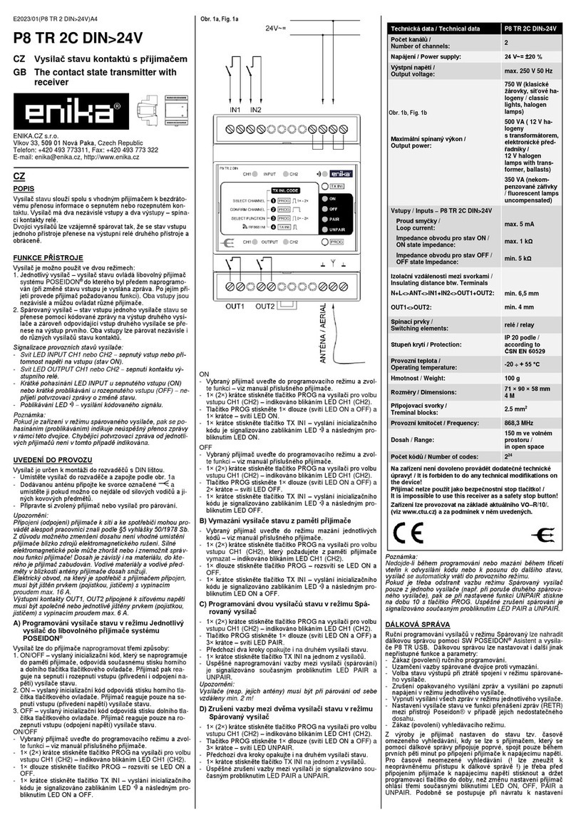
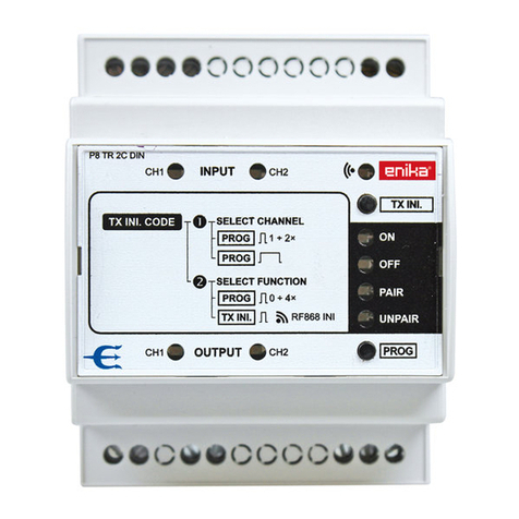
- LED INPUT CH1 or CH2 lights up
the input is closed or
voltage is present on the input (ON state).
- LED OUTPUT CH1 or CH2 lights up
output relay contact
is closed.
- Long-flashing LED INPUT for the closed input (ON) or
short-blinking for open input (OFF)
acknowledgement
message on the state change has not been received.
- Flashing LED
ongoing transmission of a coded signal.
Note:
If a device is in the paired transmitter mode, extinguishing
(flashing) indicates unsuccessful transfer of a message be-
tween the pair. In this case, missing acknowledgement mes-
sage from individual receivers is not indicated.
FIRST USE
The transmitter is to be installed in DIN rail switchboards.
- Place the transmitter in a switchboard and connect it ac-
cording to fig. 1a (P8 TR 2C DIN) or fig. 1b (P8 TR 2U DIN).
- Connect the supplied aerial to the terminal and locate it
as far from power wires and other metal objects as possi-
ble.
- Prepare the selected receiver or transmitter for pairing.
Notes:
Only qualified person can connect (disconnect) the receiver to
(from) the mains and appliance.
Due to the risk of reducing the detection zone, it is not rec-
ommended to locate the receiver near sources of electromag-
netic interference. A strong electromagnetic field may impair
or disable correct functioning of the receiver! The detection
zone depends on the material in which the receiver is built.
Conductive materials and items near the receiver aerial de-
crease its operating range.
Output contacts OUT1, OUT2 connected to the mains voltage
must be together or separately protected by a fuse or by a cir-
cuit breaker with the breaking current max. 6 A.
A) Programming of a state transmitter in the Single
transmitter mode in any receiver of the
POSEIDON®system.
There are three ways of programming the transmitted to a re-
ceiver:
1. ON/OFF –the sent initialization code programmed in the
receiver memory corresponds to simultaneous pressing of
the upper and lower button of the pushbutton controller.
The receiver will react to both closing and opening of the
input (voltage and no voltage state) of the state transmitter.
2. ON –the sent initialization code corresponds to pressing of
the upper button of the pushbutton controller. The receiver
will react only to closing of the input (voltage state) of the
state transmitter.
3. OFF –the sent initialization code corresponds to pressing
of the lower button of the pushbutton controller. The receiv-
er will react only to opening of the input (no voltage state) of
the state transmitter.
ON/OFF
- Set the selected receiver to the programming mode and se-
lect a function –see the manual of the appropriate receiver.
- Press (brief press) the PROG button on the receiver once
(twice) to select input CH1 (CH2) –it will be indicated by
flashing LED CH1 (CH2).
- - Press (long press) the PROG button once –LED ON and
OFF will light up.
- Press (brief press) the TX INI button once –sending of the
initialization code will be indicated by flashing LED and a
subsequent short blink of LED ON and OFF.
ON
- Set the selected receiver to the programming mode and se-
lect a function –see the manual of the appropriate receiver.
- Press (brief press) the PROG button on the receiver once
(twice) to select input CH1 (CH2) –it will be indicated by
flashing LED CH1 (CH2).
- Press (long press) the PROG button once (LED ON and
OFF will light up) and then (brief press) once again –LED
ON will light up.
- Press (brief press) the TX INI button once –sending of the
initialization code will be indicated by flashing LED and a
subsequent short blink of LED ON.
OFF
- Set the selected receiver to the programming mode and se-
lect a function –see the manual of the appropriate receiver.
- Press (brief press) the PROG button on the receiver once
(twice) to select input CH1 (CH2) –it will be indicated by
flashing LED CH1 (CH2).
- Press (long press) the PROG button once (LED ON and
OFF will light up) and then (brief press) twice again –LED
OFF will light up.
- Press (brief press) the TX INI button once –sending of the
initialization code will be indicated by flashing LED and a
subsequent short blink of LED OFF.
B) How to delete a transmitter from the receiver
memory
- Set the selected receiver to the code deleting mode –see
the manual of the appropriate receiver.
- Press (brief press) the PROG button on the receiver once
(twice) to select the input CH1 (CH2) that you want to de-
lete from the receiver memory –it will be indicated by flash-
ing LED CH1 (CH2).
- - Press (long press) the PROG button once –LED ON and
OFF will light up.
- Press (brief press) the TX INI button once –sending of the
initialization code will be indicated by flashing LED and a
subsequent short blink of LED ON and OFF.
C) Programming two state transmitters in the Paired
transmitter mode
- Press (brief press) the PROG button on the receiver once
(twice) to select input CH1 (CH2) –it will be indicated by
flashing LED CH1 (CH2).
- Press (long press) the PROG button once (LED ON and
OFF will light up) and then (brief press) three times –LED
PAIR will light up.
- Repeat the previous two steps on the second state trans-
mitter as well.
- Press (brief press) the TX INI button on one of the transmit-
ters once.
- Successful programming of the connection (pairing) be-
tween the transmitters will be indicated by a simultaneous
short blink of LED PAIR and UNPAIR.
Note:
When devices are paired, the minimal distance between them
(their aerials) is 2 m!
D) Disconnecting (unpairing) two state transmitters in
the Paired transmitter mode
- Press (brief press) the PROG button on the receiver once
(twice) to select input CH1 (CH2) –it will be indicated by
flashing LED CH1 (CH2).
- Press (long press) the PROG button once (LED ON and
OFF will light up) and then (brief press) three times –LED
UNPAIR will light up.
- Repeat the previous two steps on the second state trans-
mitter as well.
- Press (brief press) the TX INI button on one of the transmit-
ters once.
- Successful unpairing of the connection between the trans-
mitters will be indicated by a simultaneous short blink of
LED PAIR and UNPAIR.
Notes:
If no code is transmitted or no move to another state is per-
formed within 30 seconds when programming or deleting the
device, the transmitter automatically returns to the operating
mode.
If connection of the Paired transmitter mode is to be removed
from one of the transmitters only (for example, if the other
paired transmitter is faulty), press the PROG button (while the
UNPAIR function is enabled) for 10 s. Successful unpairing
will be indicated by a simultaneous short blink of LED PAIR
and UNPAIR.
REMOTE MANAGEMENT
Manual programming of transmitters in the Paired mode can
be substituted by remote management using the SW POSEI-
DON®Assistant tool and the P8 TR USB transmitter. You can
use remote management to even set other functions and pa-
rameters that cannot be accessed otherwise:
- Disable (enable) manual programming.
- Lock the connection of the paired pair against deletion.
- Select the state of outputs in case of lost connection in the
Paired transmitter mode.
- Cancel repeated transmission of messages and transmis-
sion after powering up in the Single transmitter mode.
- Disable transmission of all messages in the Single transmit-
ter mode.
- Setting up the state transmitter for a function of retransmis-
sion of messages between Poseidon® devices if the range
is not sufficient.
- Disable (enable) search mode.
By default, the receiver is set to the so-called state of time-
limited search. This means that when a receiver is being con-
nected using remote management for the first time, it is possi-
ble to connect to it only within the first five minutes from con-
necting it to the supply voltage. To enable time-unlimited
search (can be misused to gain unauthorized access to re-
mote management!), before you connect the receiver to the
supply voltage, press and hold the programming button until
the receiver indicates the change by three simultaneous
flashes of LED ON, OFF, PAIR and UNPAIR. Similarly, use
this procedure to return to time-limited search; the only differ-
ence is indication by only one short blink.
The current setting of the search mode can be ascertained
while connecting the receiver to the supply voltage. Three
short blinks of LED ON, OFF, PAIR and UNPAIR indicate un-
limited search, one short blink indicates time-limited search,
no blink indicates searching is disabled.
CONNECTING THE EXTERNAL AERIAL
If you face problems with range or if the distance between the
devices is great, an external aerial must be used.
Recommended types of aerials: P8 A INT1, P8 A INT2, P8 A
EXT1 and P8 A EXT2.
Connect the aerial using a 50-Ω coaxial cable. Connect the
center wire of the cable to the terminal instead of the wire
aerial and connect shielding to the terminal.
Do not place the aerial close to metal parts.
RESET TO DEFAULTS
If you need to cancel all function and parameter settings, you
can return to the manufacturer's default settings.
- Press and hold the button on the receiver while the receiver
is connected to the supply voltage until LED ON, OFF,
PAIR and UNPAIR light up (approx. 10 s).
- While the LEDs are lit up (approx. 3 s), release the button
and press it briefly again.
- Resetting to defaults is indicated by simultaneous short
blink of LED PAIR and UNPAIR.
Note:
When restoring defaults, the connection of the Paired trans-
mitter mode will be cancelled as well!
Visit www.enika.cz/poseidon for details.
ENIKA.CZ s.r.o. hereby declares that this P8 TR 2C/U DIN
complies with the essential requirements and other relevant
provisions of Directive 1999/5/EC.
Prohlášení o shodě
Výrobce: ENIKA.CZ s. r. o.
190 00 PRAHA 9, Pod Harfou 933/86
IČO: 28218167
tímto prohlašuje, že výrobek
typové označení: P8 TR 2C DIN
P8 TR 2U DIN
specifikace: ---
druh výrobku: vysílač stavu kontaktů s přijímačem (2C)
vysílač stavu napětí s přijímačem (2U)
frekvence: 868,3 MHz
vf výkon: 10 dBm
citlivost: -110 dBm
- je ve shodě se základními požadavky NV 426/2000 Sb. v platném znění
a s NV 481/2012 Sb. v platném znění
- odpovídá základním požadavkům a dalším ustanovením evropské di-
rektivy
1999/5/ES
(R&TTE) (Směrnice o radiových zařízeních a teleko-
munikačních koncových zařízeních a vzájemném uznávání jejich shody)
a evropské direktivy 2011/65/EU (RoHS)
- splňuje požadavky těchto norem a předpisů:
rádiové parametry, EMC: ČSN ETSI EN 300220-1 V2.1.1:2006
ČSN ETSI EN 300220-2 V2.1.1:2006
EN 301 489-1 V1.5.1:04
elektrická bezpečnost: ČSN EN 60 669-2-1 ed.3:05
ČSN EN 60 669-1 ed.2:03
Toto prohlášení je vydáno na výhradní odpovědnost výrobce.
V Nové Pace dne 28.02.2013 ing. Vladimír Militký,
řízení sytému jakosti


