QUICK START GUIDE
EPC – EFFICIENT POWER CONVERSION CORPORATION | WWW.EPC-CO.COM | COPYRIGHT 2018 | | 5
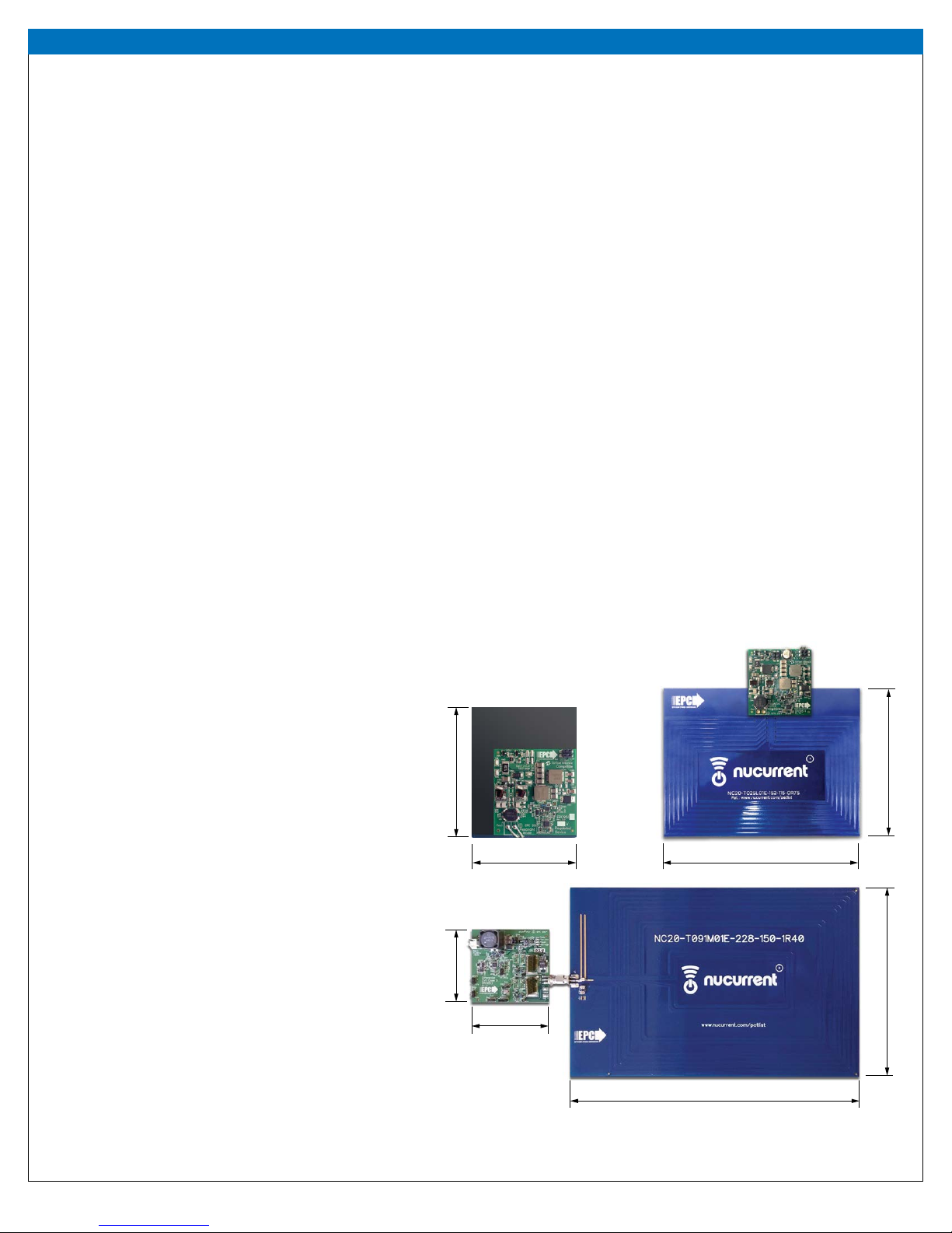
Demonstration System EPC9129
NOTE. The amplier supply voltage VAMP is absent from the equation
as it is accounted for by the voltage transition time. The COSS of the
EPC8010 eGaN FETs is on the same order of magnitude as the gate
driver well capacitance Cwell which as a result must now be included
in the ZVS timing calculation. The charge equivalent capacitance of
the eGaN FETs can be determined using the following equation:
(2)
To add additional immunity margin for shifts in coil impedance, the
value of LZVS can be decreased to increase the current at turn o
of the devices (which will increase device losses). Typical voltage
transition times range from 2 ns through 8 ns. For the dierential case
the voltage and charge (COSSQ) are doubled when calculating the ZVS
inductance.
The Source Coil
Figure 4 shows the schematic for the source coil which is Class 4
AirFuel compliant. The matching network includes only series tuning.
The matching network series tuning is dierential to allow balanced
connection and voltage reduction for the capacitors.
The Device Boards
Figure 5 shows the basic schematic diagram of the EPC9513 and
EPC9514 device boards which comprises a tuning circuit for the device
coil with a common-mode choke for EMI suppression, a high frequency
rectier and SEPIC converter based output regulator. The EPC9513 is
powered using a Category 3 AirFuel Alliance compliant device coil and
the EPC9514 is powered using a Category 5 AirFuel Alliance compliant
device coil Both are by default tuned to 6.78 MHz for the specic coil
provided with it. The tuning circuit comprises both parallel and series
tuning which is also dierential to allow balanced connection and
voltage reduction for the capacitors.
The device boards have have limited over-voltage protection using a
TVS diode that clamps the un-regulated voltage to 38 V (EPC9513) or
46 V (EPC9514) . This can occur when the receive coil is placed above
a high power transmitter with insucient distance to the transmit
coil and there is little or no load connected. During an over-voltage
event, the TVS diode will dissipate a large amount of power and the red
LED will illuminate indicating an over-voltage. The receiver should be
removed from the transmitter as soon as possible to prevent the TVS
diode from over-heating.
The EPC9513 and EPC9514 can be operated with or without the
regulator. The regulator can be disabled by inserting a jumper into
position JP50 and connecting the load to the unregulated output
terminals. In regulated mode, the design of the EPC9513 and EPC9514
controller will ensure stable operation in a wireless power system. The
regulator operates at 280 kHz (EPC9513) or 300 kHz (EPC9514) and the
controller features over current protection that limits the load current
to 1 A for the EPC9513 and 2 A for the EPC9514.
The EPC9513 and EPC9514 device boards come equipped with Kelvin
connections for easy and accurate measurement of the un-regulated
and regulated output voltages. The rectied voltage current can also
be measured using the included shunt resistor. In addition, the EPC9513
and EPC9514 have been provided with a switch-node measurement
connection for low inductance connection to an oscilloscope probe to
yield reliable waveforms.
The EPC9513 is designed to operate in conjunction with EPC9127
(10 W EPC9510)
, EPC9128 (16 W EPC9509), EPC9129 (33 W EPC9512) and
EPC9121 (10 W EPC9511) transmitter units. The EPC9514 is designed to
operate in conjunction with EPC9129 (33 W EPC9512) transmitter units.
QUICK START PROCEDURE
The EPC9129 demonstration system is easy to set up and evaluate the
performance of the eGaN FET in a wireless power transfer application.
Refer to gure 1 to assemble the system and gures 8, 9, and 10 for
proper connection and measurement setup before following the testing
procedures.
The EPC9512 can be operated using any one of two alternative methods:
a. Using the pre-regulator
b. Bypassing the pre-regulator
a. Operation using the pre-regulator
The pre-regulator is used to supply power to the amplier in this mode
and will limit the coil current, power delivered or maximum supply voltage
to the amplier based on the pre-determined settings.
The main 19 V supply must be capable of delivering 2.3 ADC. DO NOT turn
up the voltage of this supply when instructed to power up the board,
instead simply turn on the supply. The EPC9512 board includes a pre-
regulator to ensure proper operation of the board including start up.
1. Make sure the entire system is fully assembled prior to making
electrical connections and make sure jumper JP1 is installed. Also
make sure the source coil and device coil with load are connected.
2. With power o, connect the main input power supply bus to J1 as
shown in gure 8. Note the polarity of the supply connector.
3. Make sure all instrumentation is connected to the system.
4. Turn on the main supply voltage to the required value (19 V).
5. Once operation has been conrmed, observe the output voltage and
other parameters on both the amplier and device boards.
6. For shutdown, please follow steps in the reverse order.
b. Operation bypassing the pre-regulator
In this mode, the pre-regulator is bypassed and the main power is
connected directly to the amplier. This allows the amplier to be
operated using an external regulator.
Note: In this mode there is no protection for ensuring the correct
operating conditions for the eGaN FETs.
When in bypass mode it is crucial to slowly turn up the supply voltage
starting at 0 V. Note that in bypass mode you will be using two supplies;
one for logic and the other for the amplier power.
1. Make sure the entire system is fully assembled prior to making
electrical connections and make sure jumper JP1 has been removed
and installed in JP50 to disable the pre-regulator and to place the
EPC9512 amplier in bypass mode. Also make sure the source coil and
device coil with load are connected.
COSSQ =
V
AMP
0
AMP
COSS (v) dv
1