QUICK START GUIDE
EPC – EFFICIENT POWER CONVERSION CORPORATION | WWW.EPC-CO.COM | COPYRIGHT 2018 | | 4
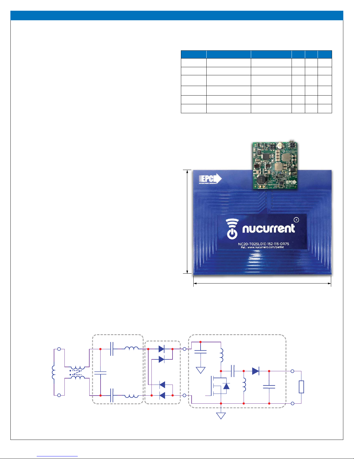
Demonstration Board EPC9514
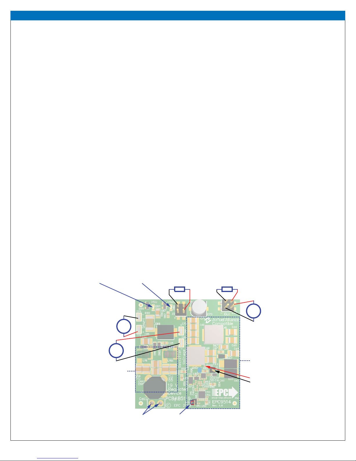
MEASUREMENT NOTES
When measuring the high frequency content such as the switch-node,
care must be taken to avoid long ground leads. An oscilloscope probe
connection (preferred method) has been built into the board to simplify
the measurement of the switch-node voltage (shown in Figure 3).
PRECAUTIONS
The EPC9514 demonstration system has limited enhanced protection
systems (thermal and electrical) and therefore should be operated with
caution. Some specic precautions are:
1. Never operate the EPC9514 receiver with a transmitter that is AirFuel
compliant as this system does not communicate with the source to
correctly setup the required operating conditions and doing so may lead
the system with an AirFuel compliant device be required to obtain
instructions on how to do this.
2. There is no heat-sink on the devices and during experimental evaluation
it is possible present conditions to the regulator that may cause the
device to overheat. Always check operating conditions and monitor the
temperature of the EPC devices using an IR camera.
3. Never connect the EPC9514 device board into your VNA in an attempt to
measure the input impedance. Doing so can severely damage the VNA.
4. Exercise caution when handling the coil while in operation as high RF
voltages are present and can lead to RF burns.
5. Please contact EPC at info@epc-co.com should the tuning of the coil
be required to change to suite specic conditions so that it can be
correctly adjusted for use with this board.
THERMAL CONSIDERATIONS
The EPC9514 demonstration system showcases the EPC2016C eGaN FETs
in a wireless energy transfer application. Although the electrical perfor-
mance surpasses that of traditional silicon devices, their relatively smaller
size does magnify the thermal management requirements. The operator
must observe the temperature of the gate driver and eGaN FET to ensure
that both are operating within the thermal limits as per the datasheets.
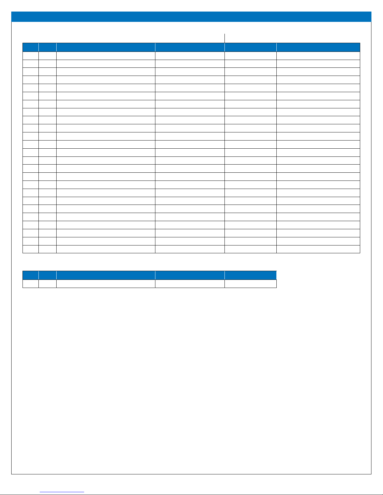
Table 2: Rev 1.0 Bill of Materials
Item Qty Reference Part Description Manufacturer Part #
1 1 C44 100 pF, 25 V Würth 885012205038
2 1 C50 100 nF, 100 V Murata GRM188R72A104KA35D
3 4 C51, C56, C57, C91 100 nF, 16 V Würth 885012205037
4 1 C53 220 pF, 50 V Murata GRM155R71H221KA01D
5 2 C55, C90 1 μF, 25 V TDK C1005X5R1E105M050BC
6 6 C61, C62, C63, C68, C71, C72 10 μF, 50 V Taiyo Yuden UMK325BJ106MM-T
7 3 C64, C65, C66 22 μF, 35 V TDK
C3216JB1V226M160AC
8 1 C67 10nF, 200 V Kemet
C0603C103K2RACTU
9 1 C70 10 μF, 50 V Nichicon
UZR1H100MCL1GB
10 1 C84 100 nF, 50 V Murata
GRM188R71H104KA93D
11 1 C85 10 μF, 50 V Taiyo Yuden UMK325BJ106MM-T
12 1 C92 22 pF, 50 V Würth 885012005057
13 2 CM1, CM11 390 pF Vishay VJ1111D391KXLAJ
14 1 Coil Receive Coil NuCurrent NC20-T025L01E-152-115-0R75
15 1 D51 30 V, 500 mA ST STPS0530Z
16 1 D60 100 V, 5 A Diodes PDS5100-13
17 1 D67 200 V, 1 A Diodes Inc. DFLS1200
18 4 D80, D81, D82, D83 60 V 1 A Diodes Inc. PD3S160-7
19 1 D84 LED 0603 Green Lite-On LTST-C193KGKT-5A
20 1 D85 2.7 V, 250 mW Nexperia BZX84-C2V7,215
21 1 D86 LED 0603 Red Lite-On LTST-C193KRKT-5A
22 1 D87 43 V, 250 mW Nexperia BZX84-C43,215
23 1 D88 44 V, 51.6 A
Littelfuse SMDJ36A
24 1 GP60 .1" Male Vert.
Würth 61300111121
25 2 J2, J3 .1" Male Vert. Amphenol FCI
95278-101A04LF
(continued on next page)