EPC 611 Specification sheet

Manual epc611 Evaluation Kit
How to get started
General Description
The evaluation kit for the epc611 chip is a tool to learn about the
functionality and performance of the epc611 chip. It consists of two
implementations of the chip into typical modules:
■TO >range 611: A range finder, where the 64 pixels are com-
bined into one cluster pixel. This range finder operates up to 15
meters and allows a measurement accuracy in the cm range.
■TO >frame611: A tiny imager with 8x8 pixels and an operating
range of two meters. This device allows e.g. people counting,
simple gesture recognition, etc.
Both modules operate also under full sunlight condition on the tar-
get, to demonstrate the outdoor capabilities.
This document presents an overview of the operation and function-
ality of the epc611 Evaluation Kit. It also contains the schematic di-
agrams which can be used as reference designs. In addition to that
the complete firmware of the two modules comes in C source code,
to support the implementation of your own modules.
Features
■A quick introduction to the epc611 3D-TO chip
■Complete development system for applications using the epc611
chip as a range-finder or 8x8 pixel imager
■The basic epc611 chip operation modes can be evaluated
■Includes TO >range 611, TO >frame 611 and USB adapter
■Range-finder TO >range 611: OV 0.18° (h/v)
Operating range up to 15m on white targets
■8x8 pixel imager TO >frame 611: OV 12° (h/v)
OV for near-field gesture control
■Log section to capture single images and picture sequences for
further processing
■User software (PC/Mac) with visualization and logging features. It
includes all the source code libraries for development.
Applications
■Evaluation and development support
igure 1: epc611 evaluation kit
© 2018 ESPROS Photonics Corporation
Characteristics subject to change without notice
1 / 15 Manual_epc611_Evalkit-V1.01
www.espros.com
Ihr autorisierter Distributor
Neumüller Elektronik GmbH
Neumüller Elektronik GmbH | Gewerbegebiet Ost 7 | 91085 Weisendorf | +49 9135 73666-0 | www.neumueller.com | [email protected]

1. Precaution and Safety
Eye safety: Do not look directly into t e camera under operation. Depending on t e mode of operation, t e camera device
emits ig ly concentrated non-visible infrared lig t. It can be azardous to t e uman eye. T e use of t ese devices as
to follow t e safety precautions given in IEC 60825-1 and IEC62471.
Some of the camera modules are bare electronic devices without a housing surround. Therefore, handle them with the necessary
ESD precaution.
Over-voltage: Use only power supplies which correspond to the datasheet of the cameras to avoid damage of the devices or
cause danger for humans.
Cable-tripping: Place the sensors on solid ground or fix it correctly on a solid support. Place cables carefully. alling devices can
be damaged.
The sensors comes with their own calibrated firmware. or proper operation of the sensors, upload the correct firmware with the
evaluation kit to the sensors according the instructions given herein.
Take care that the lens surfaces of the cameras do not get soiled. Do not touch them. Otherwise loss of performance occurs.
EMC compatibility: The epc611 Evaluation Kit is designed on module level. It is not an EMC certified device. It is the responsibility
of the user to operate it in compliance with the EMC regulations.
The epc611 Evaluation Kit is designed on module level. It is NOT a CE, UL, CSA certified device. It is the users responsibility to
operate it in compliance with the relevant regulations.
The cameras of the epc611 Evaluation Kit and their software may only be be used in accordance with the information contained in
their datasheets.
These devices may not be used in safety applications, explosive atmospheres or in radioactive environment.
Limited warranty - Loss of warranty
The epc611 Evaluation Kit should only be installed and used by authorized persons. All instructions in this datasheet and in the re -
lated documents shall be followed and fully complied with. In addition, the installer and user is required to comply with all local
laws and regulations. Should any of these instructions not be carefully followed, serious injury may occur. The installer and user is
fully responsible for the safe use and operation of the system. It is the sole responsibility of the installer and the user to ensure that
this product is used according to all applicable codes and standards, in order to ensure safe operation of the whole application.
Any alteration to the devices by the buyer, installer or user may result in unsafe operating conditions. ESPROS Photonics AG is
not responsible for any liability or warranty claim which results from such manipulation or disregarding of given operating instruc -
tions.
UPDATES
ESPROS P otonics is constantly striving to provide compre ensive and correct product information. T erefore, please c eck
our website regularly for updated versions of datas eets and documentations: www.espros.com
Download the current Datasheet epc611: www.espros.com → Downloads → Datasheets → Chips
Download the current Datasheet TO >range 611 or TO >frame 611: www.espros.com → Downloads → Datasheets →
Camera_and_Modules
Download the current Manual epc611_Evalkit: www.espros.com → Downloads → Datasheets → Evaluation_Kits
Always download and use the latest epc611 Evaluation Kit software.
Questions: Send an email with your request to your local sales office or to [email protected]
Update the epc611 Evaluation Kit software : Go to the folder “ESPROS_epc611_Evaluation_Kit_Software_vX.X”. Read the
Readme file and follow the instructions accordingly.
© 2018 ESPROS Photonics Corporation
Characteristics subject to change without notice
2 / 15 Manual_epc611_Evalkit-V1.01
www.espros.com
Ihr autorisierter Distributor
Neumüller Elektronik GmbH
Neumüller Elektronik GmbH | Gewerbegebiet Ost 7 | 91085 Weisendorf | +49 9135 73666-0 | www.neumueller.com | [email protected]

Table of Contents
1. Precaution and Safety ................................................................................................................................ 2
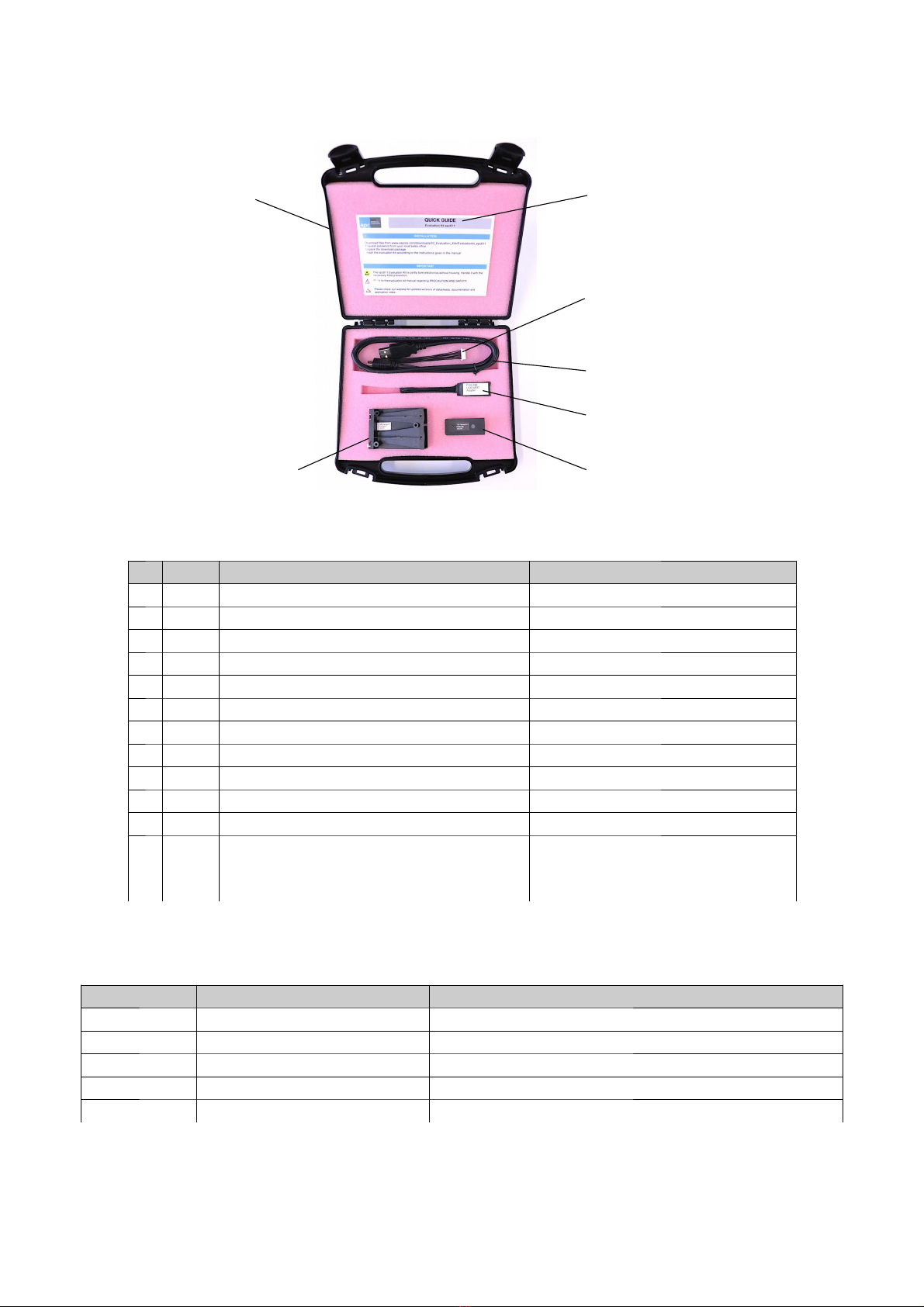
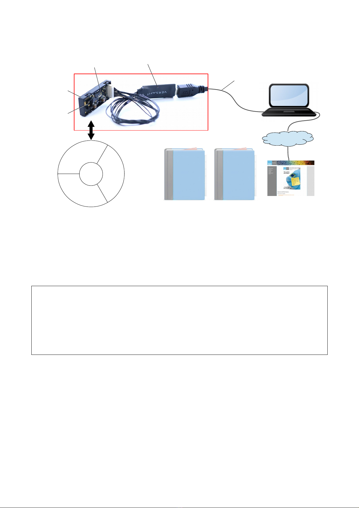
2. epc611 evaluation kit .................................................................................................................................. 4
2.1. Scope of delivery ................................................................................................................................................................................. 4
2.2. Ordering information ............................................................................................................................................................................ 4
3. Hardware ...................................................................................................................................................... 6
3.1. TO >range 611 and TO >frame 611 ................................................................................................................................................. 6
3.1.1. Technical data ............................................................................................................................................................................ 6
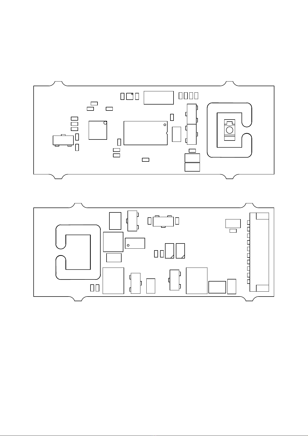
3.1.2. PCB assembly of the TO >range 611 ....................................................................................................................................... 6
3.1.3. Schematics TO >range 611 ...................................................................................................................................................... 7
3.1.4. TO >frame 611 .......................................................................................................................................................................... 8
3.2. USB-UART adapter ............................................................................................................................................................................. 8
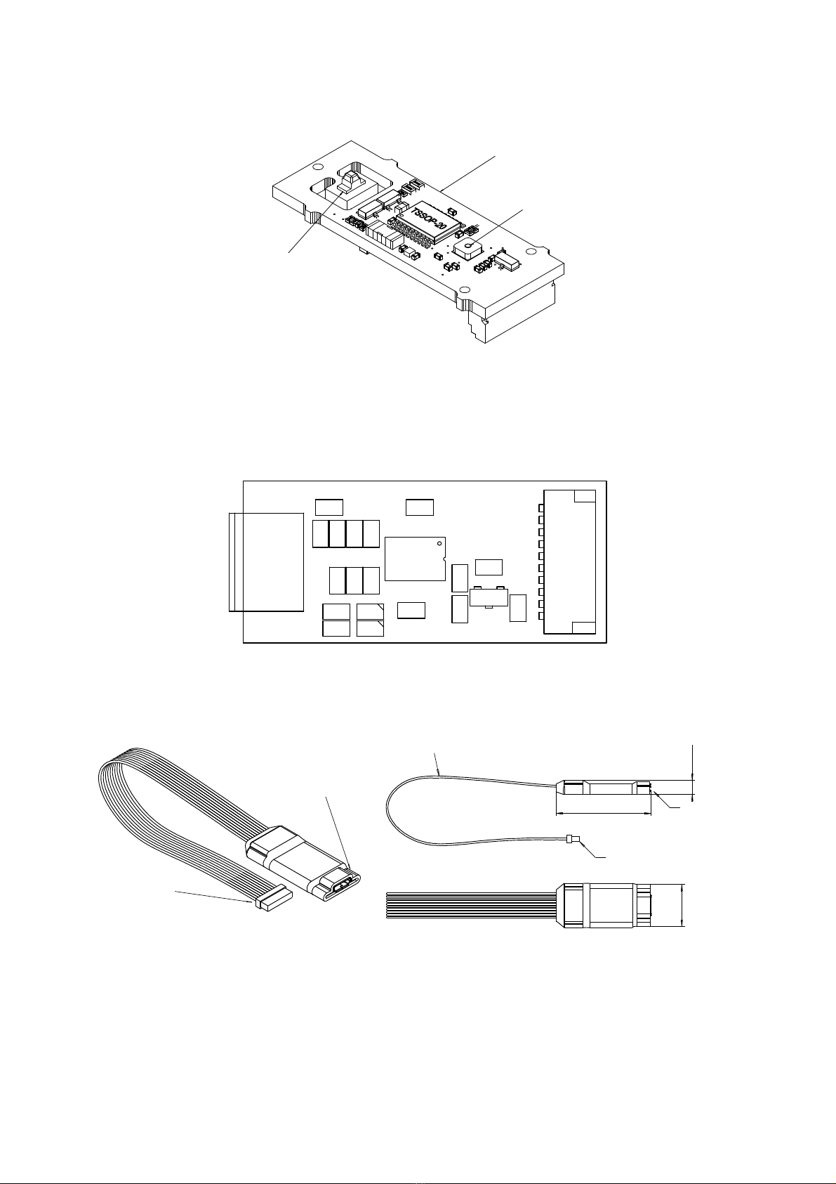
3.2.1. Assembly USB-UART adapter ................................................................................................................................................... 8
3.2.2. USB-UART adapter drawing ...................................................................................................................................................... 8
3.2.3. Schematics USB-UART adapter ................................................................................................................................................ 9
4. Installation and setup ............................................................................................................................... 10
4.1. Setup the epc611 evaluation kit system ............................................................................................................................................ 10
4.2. Software, software development kit (SDK) and application tools ..................................................................................................... 10
4.3. Software installation ........................................................................................................................................................................... 11
5. GUI functionality ....................................................................................................................................... 12
5.1. Start the GUI software ....................................................................................................................................................................... 12
5.2. Operate the sensors .......................................................................................................................................................................... 12
5.3. Special functions TO >frame 611 ..................................................................................................................................................... 12
5.4. Miscellaneous functions .................................................................................................................................................................... 13
6. Maintenance and disposal ....................................................................................................................... 14
6.1. Maintenance ...................................................................................................................................................................................... 14
6.2. Disposal ............................................................................................................................................................................................. 14
7. Addendum ................................................................................................................................................. 14
7.1. Related documents ............................................................................................................................................................................ 14
7.2. Links ................................................................................................................................................................................................... 14
7.3. Licenses ............................................................................................................................................................................................. 14
© 2018 ESPROS Photonics Corporation
Characteristics subject to change without notice
3 / 15 Manual_epc611_Evalkit-V1.01
www.espros.com
Ihr autorisierter Distributor
Neumüller Elektronik GmbH
Neumüller Elektronik GmbH | Gewerbegebiet Ost 7 | 91085 Weisendorf | +49 9135 73666-0 | www.neumueller.com | [email protected]

2. epc611 evaluation kit
2.1. Scope of delivery
➀ Box ➆ Quick Guide
➂ TO >frame 611➁ TO >range 611
➄ Micro USB cable
➃ USB-UART Adapter
➅ Connection
cable 10 pin
igure 2: epc611 evaluation kit overview
No Pieces Designation Remarks
➀1 Box
➁1 TO >range 611
➂1 TO >frame 611
➃1 USB-UART adapter, includes connector 10 pin USB 2.0, micro plug
➄1 Micro USB cable 2.0, A plug - micro plug
➅1 Cable 10 Pin JST 1.0 mm (L=76 mm) for customized connection
➆1 epc611 Quick Guide
Manual epc611 evaluation kit available at www.espros.com → Downloads
Datasheet epc611 available at www.espros.com → Downloads
Datasheet TO >range 611 available at www.espros.com → Downloads
Datasheet TO >frame 611 available at www.espros.com → Downloads
Use the application and configuration software
“ESPROS_epc611_Evaluation_Kit_Software_vX.X”.
It includes the corresponding tools and software devel-
opment kit (SDK).
available at www.espros.com → Downloads
Table 1: Bill of material of the delivery
2.2. Ordering information
Part Number Part Name Remarks
P100 487 epc611 Evaluation Kit Includes TO >range 611, TO >frame 611, USB adapter and cables
P100 483 TO >range 611 Distance measurement engine, Spot 3 x3 mm @ 1m, range 0 ... 15m
P100 499 TO >frame 611 Distance measurement engine, OV 12° (h/v), range 0 … 2m
P100 498 USB-UART Adapter
P100 516 Cable 10 Pin JST 1.0 mm (L=76 mm) or customized connection
Table 2: Ordering Information epc611 evaluation kit
© 2018 ESPROS Photonics Corporation
Characteristics subject to change without notice
4 / 15 Manual_epc611_Evalkit-V1.01
www.espros.com
Ihr autorisierter Distributor
Neumüller Elektronik GmbH
Neumüller Elektronik GmbH | Gewerbegebiet Ost 7 | 91085 Weisendorf | +49 9135 73666-0 | www.neumueller.com | [email protected]

igure 3: epc611 evaluation kit igure 4: TO >frame 611 (left) and TO >range 611 (right)
igure 5: TO >range 611 and USB-UART adapter igure 6: TO >frame 611 and USB-UART adapter
igure 7: GUI – TO >range 611 igure 8: GUI – TO >frame 611
© 2018 ESPROS Photonics Corporation
Characteristics subject to change without notice
5 / 15 Manual_epc611_Evalkit-V1.01
www.espros.com
Ihr autorisierter Distributor
Neumüller Elektronik GmbH
Neumüller Elektronik GmbH | Gewerbegebiet Ost 7 | 91085 Weisendorf | +49 9135 73666-0 | www.neumueller.com | [email protected]

3. Hardware
3.1. TOF>range 611 and TOF>frame 611
3.1.1. Tec nical data
The technical data of TO >range 611 and TO >frame 611 are specified in the corresponding datasheets.
3.1.2. PCB assembly of t e TOF>range 611
D5
C17 IC4
C20
X1
R8
IC3
R9
R10
IC2
C9
C18
C14 C15
R5
C
A
C19
R6
C8
C16 C13
C22 C21
C23
C10
R7 R3R4
C12
D6
T2
D3
igure 9: Assembly top TO >range 611
R1
C24
L3
L1
C6
D1
IC1
C7
L2
J1
C5
C3
C4
C2
C1
D4
C11
D8 D7
R11
R1 2
R2
D2
T1
igure 10: Assembly bottom TO >range 611
© 2018 ESPROS Photonics Corporation
Characteristics subject to change without notice
6 / 15 Manual_epc611_Evalkit-V1.01
www.espros.com
Ihr autorisierter Distributor
Neumüller Elektronik GmbH
Neumüller Elektronik GmbH | Gewerbegebiet Ost 7 | 91085 Weisendorf | +49 9135 73666-0 | www.neumueller.com | [email protected]

3.1.3. Sc ematics TOF>range 611
EPC6XX_SDA_NSS
UART_TX
UART_RX
EPC6XX_MISO
EPC6XX_MOSI
+5V
GND
Imax = 25mA
Pmax = 82.5mW
Needed:
Imax (VDD=8V5) = 24mA
Pmax = 220mW
Iidle (VDD=8V5) = 18mA
Pidle = 135mW
Imax(VBS=-10V4)<250uA
GND
STM32F0
Designed for:
I_LED_max = 500mA
Frame-rate = 2000fps
Int. time = 50µs
STAT_LED1
VBS
VDDPXH
VDDA
VDD
VDDCP
VDDCORE
VDDIO
VDDPLL
EPC6XX_MOSI
EPC6XX_MISO
EPC6XX_SCLK
EPC6XX_SDA_NSS
EPC6XX_DATA_RDY
EPC6XX_EXTMOD
EN
1
LX 5
B 2
GND
4
VDD
3
IC1
NCP1403
EN_VDD
D1 BAT54S
VBS
VDD
VDDIO
Needed:
VLED=5V
Imax = 150mA
Pmax = 0.75W
V=10.4V
Imax=25mA
VCE=1.9V
Pmax=48mW
Needed:
P_max=0.3W
P_avg=0.2W
I_max=0.2A
I_avg=0.15A
Total consumption:
+5V:
Imax(5V) = 100mA
Pmax = 0.50W
+5V_LED (± 5%):
Imax = 150mA
Pmax = 0.75W
EN_VDD
UART_TX
UART_RX
Controller keeps t is voltage constant.
C1_1 compensates peaks during
LED_ON 4.1V
+5V_LED
D4 BAT54S
+5V_LED
Step-up for +8.5V and -10V
Ppeak = 130mW per
Resistor
D6
BZX84-B9V1
D7
LED
rd
C9
100n/16V
C8
100n/16V
C13
1u/10V
C16
1u/10V
C15
1u/10V
C17
100n/16V
D2
BZX84-B4V7
C20
1u/10V
EPC6XX_DATA_RDY
STAT_LED2
D5
BAT54S
R3
180 epc611
EPC6XX_CLK
TEST_H
T e circuit is designed for
500mA peak for VCSEL (laser
diode), but t e diode SFH4059
only manages 0.25A at a
duty-cycle of 20% at t e
framerate of 2'000fps
C3
100n/16V
C4
1u/10V
1 2
L2
33uH 440mA
C21
1u/10V
C22
1u/10V
SWDIO
SWCLK
TP3
SWDIO
SWCLK
R9 1k0
R10
1k2
TP9
C23
100n/16V
V=3.3VV=5V
I<1mA
TP14
TP2
TP17
TP1
P 0 (OSC_IN)
2
P 1 (OSC_OUT)
3
PA13 (SWDIO)
19 PA14 (SWCLK)
20 PB1 (TIM3_CH4) 14
PA7 (SPI1_MOSI) 13
PA6 (SPI1_MISO) 12
PA5 (SPI1_SCK) 11
PA3 9
PA10 (USART1_RX) 18
PA9 (USART1_TX) 17
PA4 (SPI1_NSS) 10
PA2 8
PA1 7
PA0 6
BOOT0
1
NRST
4
VDD
16 VDDA
5
VSS
15
IC3 STM32 030 4P6
EPC6XX_SCLK
D8
LED
gr
VOUT 1
GND
2
VIN
4
EN
3
GND
0
IC4 NCP103 3.3V
EPC6XX_CLK
MOSI 1
VDDCORE
2
DATA_RDY 3
LEDPP 4
PIN5
5
VBS
6
VDDIO
7
VDDA
8VDDHPX
9
VDD
10
VDDCP
11 LEDOD 12
EXTMOD 13
PIN14 14
XTALIN 15
XTALOUT 16
VDDPLL
17
MISO 18
nSS 19
SCLK 20
GND
21
GNDA
22
GNDLEDOD 23
GNDPLL
24
IC2 epc611
R8
4k7
R2
22
1
2
3
4
5
6
7
8
9
10
J1
BM10B-SRSS-TB_vertical
1 3
2
X1
XTAL 4MHz
R12
1k0
R11
1k0
L1 10uH
T2
BC846
T1
BC817-40
R1 0 Ohm
R7
15k
R4 180k R5 8R2
R6 8R2
C6
100u/10V
C5
100u/10V
C14
4u7/10V
C18
4u7/10V
C19
4u7/10V
C12
4.7n/50V
C11
10u/16V
C10
4.7u/16V
C7 4.7u/16V
EPC_LEDOD
TP18
GND
Ityp = 3mA
Imax = 29mA
Pmax = 50mW
Ipeak = 350mA
D3
S H4059
Imax=25mA
I<=1mA
Imax = 101mA
Imax=72mA @ n=75%
V=9.1V
C2
2u2/16V
C1
2u2/16V
C24
2u2/16V
L3 100nH
+5V_ ILT
TP10
TP11
TP12
TP13
TP8
TP7
TP5 TP6
TP15
TP16
igure 11: Schematics TO >range 611
© 2018 ESPROS Photonics Corporation
Characteristics subject to change without notice
7 / 15 Manual_epc611_Evalkit-V1.01
www.espros.com
Ihr autorisierter Distributor
Neumüller Elektronik GmbH
Neumüller Elektronik GmbH | Gewerbegebiet Ost 7 | 91085 Weisendorf | +49 9135 73666-0 | www.neumueller.com | [email protected]

3.1.4. TOF>frame 611
The TO >frame 611 uses the same PCB board as TO >range 611. The only differences are with the epc611 receiver chip, which has a
lens bonded to the chip and different software in the microcontroller.
PCB TO >range 611
epc611 and lens
Emitter LED
igure 12: TO >frame 611 overview
3.2. USB-UART adapter
3.2.1. Assembly USB-UART adapter
C1
R5
L1
D1
R6
R3
IC1
C6
C7
R8
T1
C8
J1
D2
R7
R1
C5
C3
C2
C4
TP1
R2
J2
COBLC2
igure 13: Assembly USB-UART adapter
3.2.2. USB-UART adapter drawing
ca. 6
ca. 36
Cable length: 76mm
Connector SHR-10V-S
ca. 16
USB-UART-Adapter
Cable 10pin - JST1.0mm
USB Connector
igure 14: USB-UART adapter including cable
© 2018 ESPROS Photonics Corporation
Characteristics subject to change without notice
8 / 15 Manual_epc611_Evalkit-V1.01
www.espros.com
Ihr autorisierter Distributor
Neumüller Elektronik GmbH
Neumüller Elektronik GmbH | Gewerbegebiet Ost 7 | 91085 Weisendorf | +49 9135 73666-0 | www.neumueller.com | [email protected]

3.2.3. Sc ematics USB-UART adapter
VBUS 1
D- 2
D+ 3
ID 4
GND 5
Shield G
J1
Micro USB B
+5V_VUSB
USB connector
USB_DN
USB_DP
1
2
3
4
5
6
7
8
9
10
J2
SM10B-SRSS-TB-side_entry
3V3OUT
10
T230XS
VCCIO 3
VCC 12
USBDM
9
USBDP
8
RESET_B
11
RXD 4
GND
5
CTS 6
CBUS2 7
CBUS1 14
CBUS0 15
GND
13
CBUS3 16
TXD 1
RTS 2
IC1
T230XS
C6
100n/50V
+5V0
C1
10n/50V
L1
100nH
R5
10k
R3 22
R6 22
C5
100n/50V
C4
4.7u/10V
VCCIO
TO _UART_TX
TO _UART_RX
TO _+5V
GND
GND
TO _+5V_LED
SWDIO
SWCLK
C8
4.7u/10V
D1
LED gr
/ NE
D2
LED rd
/ NE
R1
560
/ NE
R2
560
/ NE
Notes:
Rx/Tx definition as seen from TOF>range 611
TOF_UART_RX: USB -> TOF>range 611
TOF_UART_TX: USB <- TOF>range 611
Jumper Cable needs to be 1:1
R7
100k
C7
100n/50V
R8 1k T1
DMP2123LQ
PWREN_B
TP1
TOF>range 611 Interface
STAT_LED1
STAT_LED2
USB to UART Converter Load Switc
GND
Imax = 100 mA
Imax = 200 mA
Imax = 300 mA
Imax = 12 mA
Imax = 312 mA
C2
18p/50V
C3
18p/50V
igure 15: Schematics USB-UART adapter
© 2018 ESPROS Photonics Corporation
Characteristics subject to change without notice
9 / 15 Manual_epc611_Evalkit-V1.01
www.espros.com
Ihr autorisierter Distributor
Neumüller Elektronik GmbH
Neumüller Elektronik GmbH | Gewerbegebiet Ost 7 | 91085 Weisendorf | +49 9135 73666-0 | www.neumueller.com | [email protected]

4. Installation and setup
4.1. Setup t e epc611 evaluation kit system
API
UART
API
HW I/O
Sensor
firmware
3D TO
kernel
epc611 chip
USB PC with MS-Windows
Mac with OSX
Customer
Application
Internet
Open Source
Tools
Illumination
www.espros.com
download center
TO >frame 611
USB-UART adapter
igure 16: Principal system setup e.g. for TO >frame 611
Refer also to igure 5 and igure 6.
The epc611 evaluation kit uses the TO >range 611 and TO >frame. They are general purpose camera/sensor modules based on the
epc611 chip:
■The sensor/camera is based on a board with a small microprocessor.
■The sensors, with their UART interface, communicate with the computer via USB-UART adapter, using a virtual “COM” port.
■The USB interface supplies the sensor with power.
■The application firmware on the sensors have a 3D-TO kernel which manages the camera, including correction algorithms.
Connecting t e system
1: Connect the USB-UART adapter to the TO >range 611 or TO >frame 611 and the USB cable.
2: Plug the USB cable to the computer. System is powered up and ready to use.
3: Run the evaluation kit software
Disconnecting t e system
1: Close the evaluation kit software
2: Disconnect the USB cable from the computer to power-off USB-UART adapter and the sensor.
4.2. Software, software development kit (SDK) and application tools
ESPROS Photonics supports the user's development and application by having various support tools available e.g. software development
kit (SDK), updates and program downloads for the epc611 chip, application interfaces (API), etc. They are all available by downloading the
ESPROS_epc611_Evaluation_Kit_Software_vX.X. Updates of camera firmware are also included in the package.
After the download, first read the README and CHANGELOG files to get the latest operation and application information.
© 2018 ESPROS Photonics Corporation
Characteristics subject to change without notice
10 / 15 Manual_epc611_Evalkit-V1.01
www.espros.com
Ihr autorisierter Distributor
Neumüller Elektronik GmbH
Neumüller Elektronik GmbH | Gewerbegebiet Ost 7 | 91085 Weisendorf | +49 9135 73666-0 | www.neumueller.com | [email protected]

4.3. Software installation
The epc611 evaluation kit uses software which can be downloaded from the ESPROS homepage at www.espros.com. Click the link
“Downloads” as shown below:
igure 17: ESPROS homepage with the Download link
You will see a folder structure. Go to the subfolder 03_Evaluation Kits/Evaluationkit_epc611 and download the corresponding file
“ESPROS_epc611_Evaluation_Kit_Software_vX.X” for Windows or Mac. Unpack the file. You will get a folder structure as shown in
igure 18.
GUI files for Windows
GUI file for Mac
Source files GUI
Source files firmware
TO >range611 and TO >frame611
Most actual information about
the evaluation kit and the sensors
igure 18: older structure after installation
Note:
The ESPROS_epc611_Evaluation_Kit_Software_vX.X does not need any driver installation. It can be run directly.
© 2018 ESPROS Photonics Corporation
Characteristics subject to change without notice
11 / 15 Manual_epc611_Evalkit-V1.01
www.espros.com
Ihr autorisierter Distributor
Neumüller Elektronik GmbH
Neumüller Elektronik GmbH | Gewerbegebiet Ost 7 | 91085 Weisendorf | +49 9135 73666-0 | www.neumueller.com | [email protected]

5. GUI functionality
5.1. Start t e GUI software
Note:
irst, after installation of a new software release, read the README and CHANGELOG files of the download package to get latest evalua -
tion kit information.
After starting the “ESPROS_TO -imager_GUI_611” application file, the software connects automatically to the device. The corresponding
control window of the Graphical User Interface (GUI) appears.
igure 19: Control window after startup for TO >range 611 igure 20: Control window after startup for TO >frame 611
The GUI consists of different windows: The control window is on top, the corresponding display windows are on a lower level. The control
window is used to set parameters, choose the way of displaying the camera data or images and to log data. It consists of two sections: Left
is the dock with the Apps and right is the control section.
Most of the functions are self-explanatory and are not described here. However, some tool tip windows support the usage.
5.2. Operate t e sensors
Press the “Start” button. You get get the main data window:
igure 21: Main data window for TO >range 611 igure 22: Main data window for TO >frame 611
5.3. Special functions TOF>frame 611
igure 23: Surface plot distance and amplitude igure 24: Bar graph plot distance and amplitude
© 2018 ESPROS Photonics Corporation
Characteristics subject to change without notice
12 / 15 Manual_epc611_Evalkit-V1.01
www.espros.com
Ihr autorisierter Distributor
Neumüller Elektronik GmbH
Neumüller Elektronik GmbH | Gewerbegebiet Ost 7 | 91085 Weisendorf | +49 9135 73666-0 | www.neumueller.com | [email protected]

igure 25: Gesture mode surface plot:
Distance and moving direction
igure 26: Gesture mode bar graph:
Distance and moving direction
5.4. Miscellaneous functions
igure 27: Pixel info TO >range 611 igure 28: Pixel info TO >frame 611
Yellow arrows show selected pixel
igure 29: GUI, firmware and chip info TO >range 611 igure 30: GUI shows pop-up tool tip window
igure 31: Log dialog igure 32: Save, reload GUI configurations
and update the firmware
© 2018 ESPROS Photonics Corporation
Characteristics subject to change without notice
13 / 15 Manual_epc611_Evalkit-V1.01
www.espros.com
Ihr autorisierter Distributor
Neumüller Elektronik GmbH
Neumüller Elektronik GmbH | Gewerbegebiet Ost 7 | 91085 Weisendorf | +49 9135 73666-0 | www.neumueller.com | [email protected]

6. Maintenance and disposal
6.1. Maintenance
The components of the device do not need regular maintenance. A functional check is recommended each time the device is taken into
operation:
■Check the mounting position and the detection area of the sensor with respect to the operational conditions. Also check that there is no
hazardous situation.
■rom time to time, clean the lens with a soft towel and a little soapy water, to remove dust or dirt.
6.2. Disposal
Disposal should be done using the most up-to-date recycling technologies for electronic components according to the local regulations and
laws. The design and manufacture of the kit's components are done in compliance with the RoHS legal regulations. Traces of dangerous
materials may be found in the electronic components, but not in harmful quantities.
7. Addendum
7.1. Related documents
■Datasheet epc611, ESPROS Photonics Corp.
■Datasheet TO >range 611, ESPROS Photonics Corp.
■Datasheet TO >frame 611, ESPROS Photonics Corp.
■Application note AN10 TO Calibration and Compensation, ESPROS Photonics corp.
■Application note AN12_Distance_Noise_Reduction_with_Kalman_ ilter, ESPROS Photonics corp.
7.2. Links
www.espros.com
www.pointcloud.org - Point Cloud Library (PCL)
www.pdal.io - Point Data Abstraction Library (PDAL)
www.opencv.org - OpenCV (OpenSource Computer Vision)
7.3. Licenses
We appreciate the use of the following open source or free software in our tools and respect the large amount of work the owners have
done:
■Putty: http://www.chiark.greenend.org.uk/~sgtatham/putty/licence.html
Copyright (C) 1997-2015 Simon Tatham
■Qt-4.8: http://www.gnu.org/licenses/old-licenses/lgpl-2.1.html
Copyright (C) 2012 Nokia Corporation
■Qwt-6.1: http://qwt.sourceforge.net/qwtlicense.html
Copyright (C) 1997 Josef Wilgen & Copyright (C) 2002 Uwe Rathmann under Qwt License, Version 1.0
■QwtPlot3D: http://qwtplot3d.sourceforge.net/web/navigation/license.txt
Copyright (C) 2003-2005 Michael Bieber
All rights reserved by the owners.
THIS SO TWARE IS PROVIDED BY THE COPYRIGHT HOLDERS AND CONTRIBUTORS "AS IS" AND ANY EXPRESS OR IMPLIED
WARRANTIES, INCLUDING, BUT NOT LIMITED TO, THE IMPLIED WARRANTIES O MERCHANTABILITY AND ITNESS OR A
PARTICULAR PURPOSE ARE DISCLAIMED. IN NO EVENT SHALL THE COPYRIGHT HOLDER OR CONTRIBUTORS BE LIABLE OR
ANY DIRECT, INDIRECT, INCIDENTAL, SPECIAL, EXEMPLARY, OR CONSEQUENTIAL DAMAGES (INCLUDING, BUT NOT LIMITED
TO, PROCUREMENT O SUBSTITUTE GOODS OR SERVICES; LOSS O USE, DATA, OR PRO ITS; OR BUSINESS INTERRUP-
TION) HOWEVER CAUSED AND ON ANY THEORY O LIABILITY, WHETHER IN CONTRACT, STRICT LIABILITY, OR TORT (IN-
CLUDING NEGLIGENCE OR OTHERWISE), ARISING IN ANY WAY OUT O THE USE O THIS SO TWARE, EVEN I ADVISED O
THE POSSIBILITY O SUCH DAMAGE.
© 2018 ESPROS Photonics Corporation
Characteristics subject to change without notice
14 / 15 Manual_epc611_Evalkit-V1.01
www.espros.com
Ihr autorisierter Distributor
Neumüller Elektronik GmbH
Neumüller Elektronik GmbH | Gewerbegebiet Ost 7 | 91085 Weisendorf | +49 9135 73666-0 | www.neumueller.com | [email protected]

IMPORTANT NOTICE
ESPROS Photonics AG and its subsidiaries (epc) reserve the right to make corrections, modifications, enhancements, improvements, and
other changes to its products and services at any time and to discontinue any product or service without notice. Customers should obtain
the latest relevant information before placing orders and should verify that such information is current and complete. All products are sold
subject to epc’s terms and conditions of sale supplied at the time of order acknowledgment.
epc warrants performance of its hardware products to the specifications applicable at the time of sale in accordance with epc’s standard
warranty. Testing and other quality control techniques are used to the extent epc deems necessary to support this warranty. Except where
mandated by government requirements, testing of all parameters of each product is not necessarily performed.
epc assumes no liability for applications assistance or customer product design. Customers are responsible for their products and applica -
tions using epc components. To minimize the risks associated with customer products and applications, customers should provide ade -
quate design and operating safeguards.
epc does not warrant or represent that any license, either express or implied, is granted under any epc patent right, copyright, mask work
right, or other epc intellectual property right relating to any combination, machine, or process in which epc products or services are used.
Information published by epc regarding third-party products or services does not constitute a license from epc to use such products or ser -
vices or a warranty or endorsement thereof. Use of such information may require a license from a third party under the patents or other in-
tellectual property of the third party, or a license from epc under the patents or other intellectual property of epc.
Resale of epc products or services with statements different from or beyond the parameters stated by epc for that product or service voids
all express and any implied warranties for the associated epc product or service. epc is not responsible or liable for any such statements.
epc products are not authorized for use in safety-critical applications (such as life support) where a failure of the epc product would reason-
ably be expected to cause severe personal injury or death, unless officers of the parties have executed an agreement specifically govern -
ing such use. Buyers represent that they have all necessary expertise in the safety and regulatory ramifications of their applications, and
acknowledge and agree that they are solely responsible for all legal, regulatory and safety-related requirements concerning their products
and any use of epc products in such safety-critical applications, notwithstanding any applications-related information or support that may
be provided by epc. urther, Buyers must fully indemnify epc and its representatives against any damages arising out of the use of epc
products in such safety-critical applications.
epc products are neither designed nor intended for use in military/aerospace applications or environments unless the epc products are
specifically designated by epc as military-grade. Only products designated by epc as military-grade meet military specifications. Buyers ac-
knowledge and agree that any such use of epc products which epc has not designated as military-grade is solely at the Buyer's risk, and
that they are solely responsible for compliance with all legal and regulatory requirements in connection with such use.
epc products are neither designed nor intended for use in automotive applications or environments unless the specific epc products are
designated by epc as compliant with ISO/TS 16949 requirements. Buyers acknowledge and agree that, if they use any non-designated
products in automotive applications, epc will not be responsible for any failure to meet such requirements.
© 2018 ESPROS Photonics Corporation
Characteristics subject to change without notice
15 / 15 Manual_epc611_Evalkit-V1.01
www.espros.com
Ihr autorisierter Distributor
Neumüller Elektronik GmbH
Neumüller Elektronik GmbH | Gewerbegebiet Ost 7 | 91085 Weisendorf | +49 9135 73666-0 | www.neumueller.com | [email protected]
Table of contents
Other EPC Motherboard manuals
Popular Motherboard manuals by other brands

IBASE Technology
IBASE Technology MB870 user manual

ASROCK Rack
ASROCK Rack ROME2D16-2T user manual

Fujitsu Siemens Computers
Fujitsu Siemens Computers D1875 Technical manual

ON Semiconductor
ON Semiconductor AR0132AT6R00XPEAH3-GEVB user manual

RS Components
RS Components Raspberry Pi model A Getting started guide

IDT
IDT ZMID520 Series user manual